Page 2280 of 2490
19.
Fit door casing. Refer to 76.34.01.
20. Fit door casing veneer panel. Refer to 76.47.11.
21. Connect ground cable to battery terminal and fit battery
cover. Refer to 86.15.15.
Page 2297 of 2490
Handles, Locks, Latches and Entry Systems - Exterior Passenger Door
Handle
Removal and Installation
Removal
1. Remove battery cover and disconnect ground cable from
battery terminal. Refer to 86.15.19.
2. Remove door casing veneer panel. Refer to 76.47.11.
3. Remove door casing for access. Refer to 76.34.01.
4. Feeding electrical harness thro ugh water shedder, carefully
peel shedder from door and pl ace adhesive face down on a
clean dry polythene sheet.
5. Position PVC inner sheet for access.
6. Disconnect door handle operating link rod from lock
assembly.
7. Slacken and remove the two handle mounting bracket
securing bolts and remove bracket from door.
8. Withdraw handle assembly from door and remove link rod
from handle.
Page 2298 of 2490
Installation
1. Fit link rod to door handle.
2. Position handle assembly on door.
3. Position mounting bracket on insi de of door and connect lock
link rod.
4. Fit and tighten mounting bracket securing bolts.
5. Reposition PVC inner sheet in door.
6. Check for satisfactory door handle operation.
7. Connect ground cable to battery terminal. Refer to 86.15.15.
8. Check for satisfactory operation of locking system.
9. Disconnect ground cable from battery terminal. Refer to
86.15.15.
10. Ensure that water shedder contact area of door is clean and
dry.
11. Position water shedder at door and carefully pass harness
through.
12. Fit and firmly seat water shedder on door ensuring
satisfactory adhesion.
13. Fit door casing. Refer to 76.34.01.
14. Fit door casing veneer panel. Refer to 76.47.11.
15. Fit ground cable to battery term inal and fit cover to battery.
Refer to 86.15.15.
Page 2302 of 2490
Installation
8. Remove lock link rod from door handle assembly.
1. Fit link rod to handle assembly.
2. Position handle assembly on door.
3. Position mounting bracket on insi de of door and connect lock
link rod.
4. Fit and tighten mounting bracket securing bolts.
5. Reposition PVC inner sheet in door.
6. Check for satisfactory door handle operation.
7. Connect ground cable to battery terminal. Refer to 86.15.15.
8. From driver door check for satisfactory operation of locking
system.
9. Disconnect ground cable from battery terminal. Refer to
86.15.15.
10. Ensure that water shedder contact area of door is clean and
dry.
11. Position water shedder at door and carefully pass harness
through.
12. Fit and firmly seat water shedder on door ensuring
satisfactory adhesion.
13. Fit door casing. Refer to 76.34.01.
14. Fit door casing veneer panel. Refer to 76.47.11.
15. Fit ground cable to battery term inal and fit cover to battery.
Refer to 86.15.15.
Page 2303 of 2490
Handles, Locks, Latches and Entry Systems - Rear Door Latch
Removal and Installation
Removal
1. Remove battery cover and disco nnect earth cable from battery
terminal. Refer to 86.15.19.
2. Remove rear door casing veneer panel. Refer to 76.47.12.
3. Remove rear door casing. Refer to 76.34.04.
4. Carefully withdraw water shedder passing harness through it
and remove water shedder from door.
5. Place water shedder adhesive face down on clean dry plastic
sheet.
6. Release door lock actuator ha rness multiplug from mounting
bracket and disconnect multiplug.
7. Position PVC inner sheet for access and disconnect door
outer handle operating ro d from lock mechanism.
8. Disconnect inner door lock operating rod from lock
mechanism and remove rod assembly.
Page 2305 of 2490

1.
Position lock mechanism at door and connect operating cable.
2. Fit and fully seat cable rear abutment securing clip.
3. Fit and fully seat lock mechanism in door and fit and tighten
securing bolts.
4. Align glass guide and fit and tighten securing bolts.
5. Fit and fully seat inner cheater finisher.
6. Align and connect inner operating rod to lock mechanism.
7. Fit outer door handle operating rod to lock
8. Check for satisfactory door handle operation.
9. Reposition inner plastic sheet.
10. Connect lock actuator harness multiplug and fit to mounting
bracket.
11. Connect ground cable to battery terminal. Refer to 86.15.15.
12. From driver door, check for satisfactory operation of locking
system.
13. Disconnect ground cable from battery terminal. Refer to
86.15.19.
14. Ensure that water shedder contact area of door is clean and
dry.
15. Position water shedder at d oor and carefully pass door
harness through.
16. Fit and firmly seat water shedde r on door ensuring satifactory
adhesion.
17. Fit door casing. Refer to 76.34.04.
18. Fit door casing veneer panel. Refer to 76.47.12.
19. Connect ground cable to battery terminal and fit battery
cover. Refer to 86.15.15.
Page 2320 of 2490

Installation
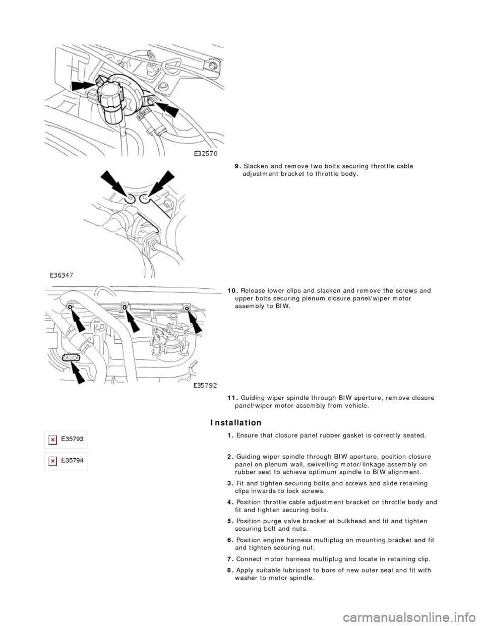
9. Slacken and remove two bolts securing throttle cable
adjustment bracket to throttle body.
10. Release lower clips and slacken and remove the screws and
upper bolts securing plenum closure panel/wiper motor
assembly to BIW.
11. Guiding wiper spindle through BIW aperture, remove closure
panel/wiper motor assembly from vehicle.
E357931. Ensure that closure panel rubbe r gasket is correctly seated.
E357942. Guiding wiper spindle through BI W aperture, position closure
panel on plenum wall, swivelling motor/linkage assembly on
rubber seat to achieve optimu m spindle to BIW alignment.
3. Fit and tighten securing bolts and screws and slide retaining
clips inwards to lock screws.
4. Position throttle cable adjustment bracket on throttle body and
fit and tighten securing bolts.
5. Position purge valve bracket at bulkhead and fit and tighten
securing bolt and nuts.
6. Position engine harness multiplu g on mounting bracket and fit
and tighten securing nut.
7. Connect motor harness multiplug and locate in retaining clip.
8. Apply suitable lubricant to bore of new outer seal and fit with
washer to motor spindle.
Page 2328 of 2490

Roof Opening Panel - Roof Opening Panel
Description and Operation
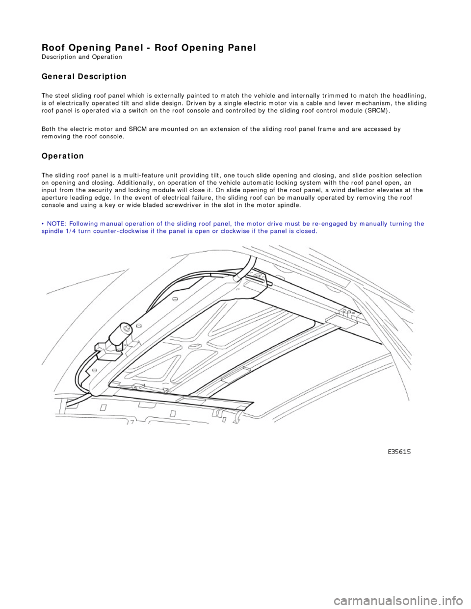
General Description
The steel sliding roof panel which is externally painted to ma tch the vehicle and internally trimmed to match the headlining,
is of electrically operated tilt and slide design. Driven by a single electric motor via a cable and lever mechanism, the slidi ng
roof panel is operated via a switch on the roof console and controlled by the sliding roof control module (SRCM).
Both the electric motor and SRCM are mounted on an extens ion of the sliding roof panel frame and are accessed by
removing the roof console.
Operation
The sliding roof panel is a multi-feature unit providing tilt, one touch slide opening and closing, and slide position selectio n
on opening and closing. Additi onally, on operation of the vehicle automatic locking system with the roof panel open, an
input from the security and lockin g module will close it. On slide opening of the roof panel, a wind deflector elevates at the
aperture leading edge. In the event of electrical failure, the sliding roof can be manually operated by removing the roof
console and using a key or wide bladed scre wdriver in the slot in the motor spindle.
• NOTE: Following manual operation of the sliding roof panel, the motor drive must be re-engaged by manually turning the
spindle 1/4 turn counter-clockwise if the panel is open or clockwise if the panel is closed.