Page 2329 of 2490

Roof Opening Panel - Motor Synchronization
General Procedures
1.
Remove sliding roof trim panel for access. Refer to 76.82.19.
2. Remove battery cover and disc onnect ground cable from
battery terminal. Refer to 86.15.19.
3. Remove roof console for ac cess. Refer to 76.13.69.90.
4. Remove sliding roof panel cont rol module. Refer to 86.76.07.
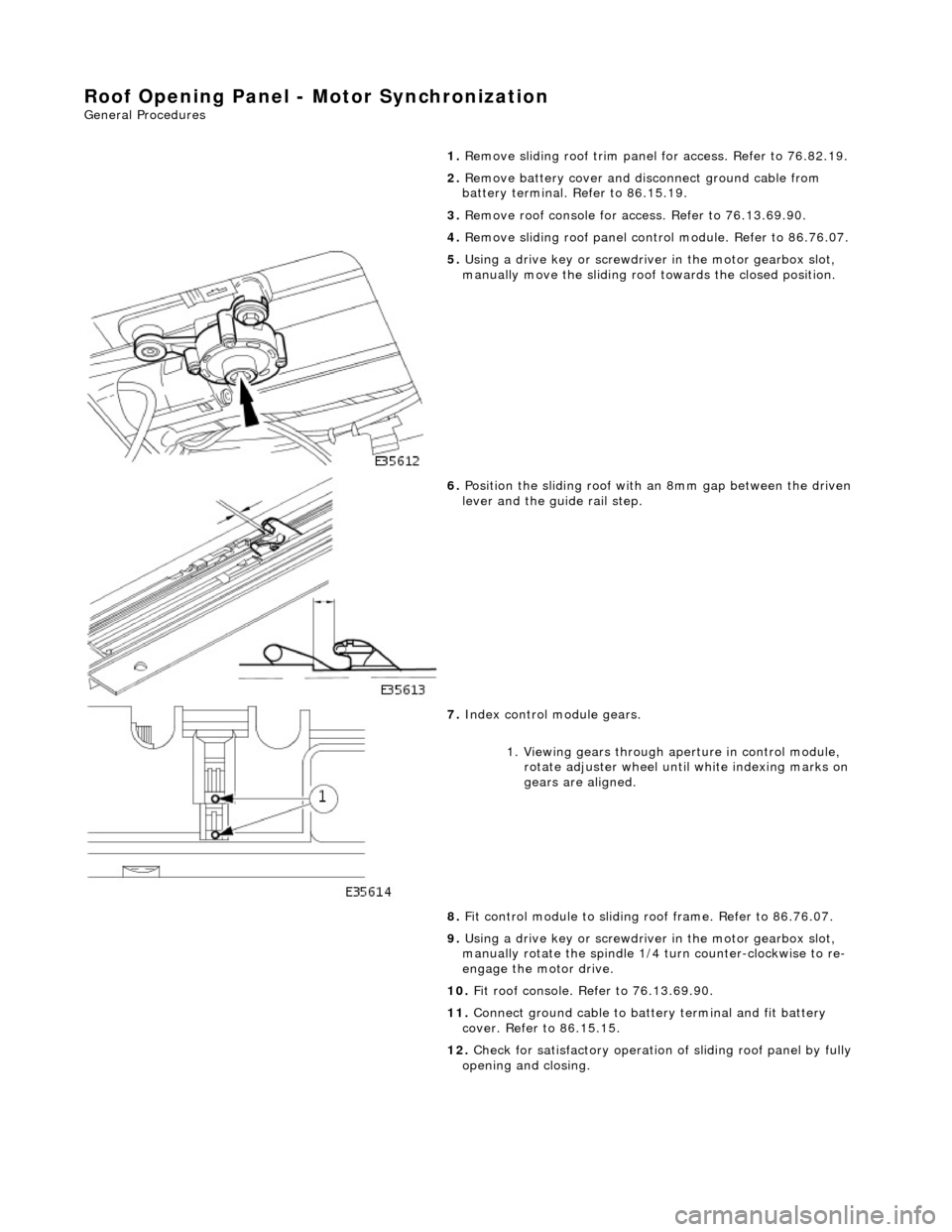
5. Using a drive key or screwdriver in the motor gearbox slot,
manually move the sliding roof towards the closed position.
6. Position the sliding roof with an 8mm gap between the driven
lever and the guide rail step.
7. Index control module gears.
1. Viewing gears through aperture in control module, rotate adjuster wheel until white indexing marks on
gears are aligned.
8. Fit control module to sliding r oof frame. Refer to 86.76.07.
9. Using a drive key or screwdriver in the motor gearbox slot,
manually rotate the spindle 1/4 turn counter-clockwise to re-
engage the motor drive.
10. Fit roof console. Refer to 76.13.69.90.
11. Connect ground cable to batt ery terminal and fit battery
cover. Refer to 86.15.15.
12. Check for satisfactory operation of sliding roof panel by fully
opening and closing.
Page 2330 of 2490
Roof Opening Panel - Roof Opening Panel Alignment
General Procedures
1.
Remove sliding roof trim panel for access. Refer to 76.82.19.
2. Turn ignition switch to position II.
3. Fully close sliding roof.
4. Turn ignition switch to po sition O and remove key.
5. Slacken sliding panel to frame securing bolts.
6. Ensuring that seal is not compressed, press sliding panel
forward.
7. Align sliding panel with roof contour.
Adjust front edge of panel to align with roof contour
within -1 +0 mm.
Adjust rear edge of panel to align with roof contour
within -0 +1 mm.
8. Ensuring that roof panel settin g is not disturbed, tighten the
outer four sliding panel to frame securing bolts.
9. Insert key and turn ig nition switch to II.
10. Check for satisfactory fit and operation by opening and
closing roof panel and re -adjust as necessary.
11. Turn ignition switch to position O.
12. Tighten all sliding panel to frame securing screws
13. Fit trim panel. Refer to 76.82.19.
Page 2331 of 2490
Roof Opening Panel - Roof Opening Panel
Removal and Installation
Removal
Installation
1.
Remove sliding roof trim panel for access. Refer to 76.82.19.
2. Slacken and remove sliding r oof panel securing bolts.
3. Carefully withdraw sliding roof panel and seal from aperture.
1. If sliding roof panel is being renewed. fit new seal as detailed
in 76.82.05.
2. Carefully position sliding roof panel in aperture.
3. Fit and tighten panel securing screws.
4. Fit trim panel. Refer to 76.82.19.
Page 2332 of 2490

Roof Opening Panel - Roof Opening Panel Frame
Removal and Installation
Removal
1. Adjust front passenger seat fu lly rearwards and fully recline
seat squab.
2. Remove battery cover and disc onnect ground cable from
battery terminal. Refer to 86.15.19.
3. Remove sliding roof flange finisher. Refer to 76.82.23.
4. Remove sliding roof trim panel. Refer to 76.82.19.
5. Remove grab handles. Refer to 501-05.
6. Remove roof console. Refer to 76.13.69.90.
7. Remove sun visors. Refer to 501-05.
8. Remove cantrail/upper A post trims. Refer to 76.13.20.
9. Remove rear quarter trim s. Refer to 76.13.13.
10. Remove front half headlining for access. refer to 76.64.15.90.
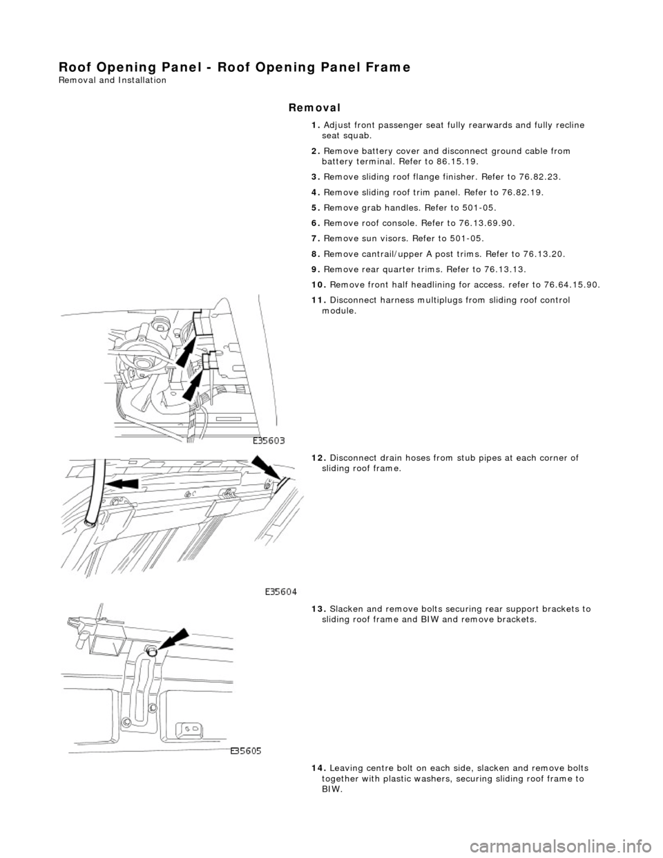
11. Disconnect harness multiplugs from sliding roof control
module.
12. Disconnect drain hoses from stub pipes at each corner of
sliding roof frame.
13. Slacken and remove bolts securi ng rear support brackets to
sliding roof frame and BIW and remove brackets.
14. Leaving centre bolt on each side, slacken and remove bolts
together with plastic washers, securing sliding roof frame to
BIW.
Page 2334 of 2490
tighten securing bolts.
7.
Align rear support brackets and tighten securing bolts.
8. Connect drain hoses to sliding roof frame stub pipes.
9. Fit headlining. Refer to 76.64.15.90.
10. Fit rear quarter trims. Refer to 76.13.13.
11. Fit cantrail/upper A post trims. Refer to 76.13.20.
12. Fit sun visors. Refer to 501-05.
13. Fit roof console. Refer to 76.13.69.90.
14. Fit grab handles. Refer to 501-05.
15. Fit sliding roof trim panel. Refer to 76.82.19.
16. Fit sliding roof flange fi nisher. Refer to 76.82.23.
17. Connect ground cable to batt ery terminal and fit battery
cover. Refer to 86.15.15.
18. Return front passen ger seat to original positions.
Page 2335 of 2490
Roof Opening Panel - Roof Opening Panel Module
Removal and Installation
Removal
1. Remove cover from battery and disconnect ground cable from
battery terminal.
2. Remove sliding roof trim panel for access. Refer to 76.82.19.
3. Using a drive key or screwdriver in the motor gearbox slot,
manually move the sliding roof towards the closed position.
4. Position the sliding roof with an 8mm gap between the driven
lever and the guide rail step.
5. Remove roof console for ac cess. Refer to 76.13.69.90.
6. Release sun visor from support and position at cantrail.
7. Remove visor support securing screw and remove support from
header.
8. Disconnect harness multiplugs from sliding roof control
module.
9. Carefully withdraw adjacent sectio n of flange finisher and edge
of headlining sufficient to prov ide access to control module.
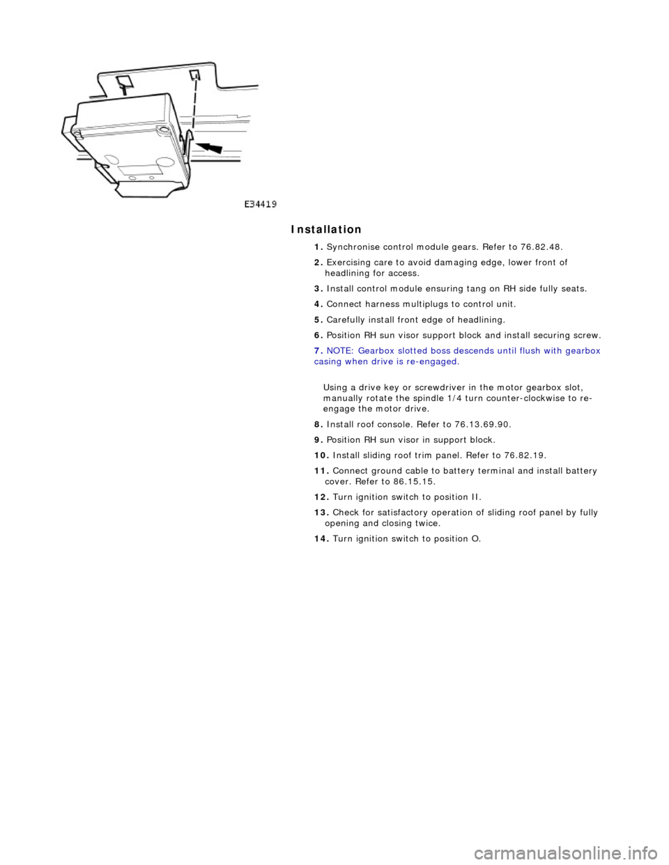
10. Depressing retaining tang on RH side of module, lower that
side and release from tang on sliding roof frame.
Page 2336 of 2490

Installation
1. Synchronise control module gears. Refer to 76.82.48.
2. Exercising care to avoid da maging edge, lower front of
headlining for access.
3. Install control module ensuring tang on RH side fully seats.
4. Connect harness multiplugs to control unit.
5. Carefully install front edge of headlining.
6. Position RH sun visor support bl ock and install securing screw.
7. NOTE: Gearbox slotted boss descends until flush with gearbox
casing when drive is re-engaged.
Using a drive key or screwdriver in the motor gearbox slot,
manually rotate the spindle 1/4 turn counter-clockwise to re-
engage the motor drive.
8. Install roof console. Refer to 76.13.69.90.
9. Position RH sun visor in support block.
10. Install sliding roof trim panel. Refer to 76.82.19.
11. Connect ground cable to batter y terminal and install battery
cover. Refer to 86.15.15.
12. Turn ignition switch to position II.
13. Check for satisfactory operation of sliding roof panel by fully
opening and closing twice.
14. Turn ignition switch to position O.
Page 2337 of 2490
Roof Opening Panel - Roof Opening Panel Motor
Removal and Installation
Removal
Installation
1. Remove battery cover and disc onnect ground cable from
battery terminal. Refer to 86.15.19.
2. Remove roof console for ac cess. Refer to 76.13.69.90.
3. Disconnect sliding roof panel motor multiplug from control
module.
4. slacken and remove sliding roof panel motor securing screws.
5. Withdraw motor assembly and remove plastic mountings.
1. Fit plastic mountings to motor.
2. Position and align motor in slid ing roof frame, ensuring that
motor body locates in outer tubes and gear engages inner
cables.