1998 JAGUAR X308 vi number
[x] Cancel search: vi numberPage 1801 of 2490
Condenser:
Multi-pass fin-over-tube type, mounted in front of the engine cooling pack and directly to the radiator.
Pressure (Bitron) switch:
Located in the discharge pipe. Provides a signal, via the A/CCM, to th e ECM, to disengage the compressor clut ch should the refrigerant pressure be
< 2 bar or > 30 bar.
Provides a hard-wired signal to the ECM, to switch the cool ing fans to HIGH speed at 22 bar rising pressure and to
LOW speed at 17,5 bar falling pressure.
Provides a hard-wired signal to the ECM, to switch the radiator cooling fans to LOW speed at 12 bar rising pressure
and to switch the fans OFF at 8 bar falling pressure.
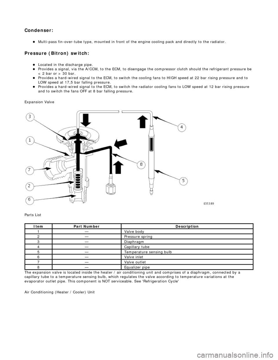
Expansion Valve
Parts List
The expansion valve is located inside the heater / air conditioning unit and comprises of a diaphragm, connected by a
capillary tube to a temperat ure sensing bulb, which regulates the valve according to temperature variations at the
evaporator outlet pipe. This component is NOT serviceable. See 'Refrigeration Cycle'
Air Conditioning (Heater / Cooler) Unit
ItemPart NumberDescription
1—Valve body
2—Pressure spring
3—Diaphragm
4—Capillary tube
5—Temperature sensing bulb
6—Valve inlet
7—Valve outlet
8—Equalizer pipe
Page 1802 of 2490
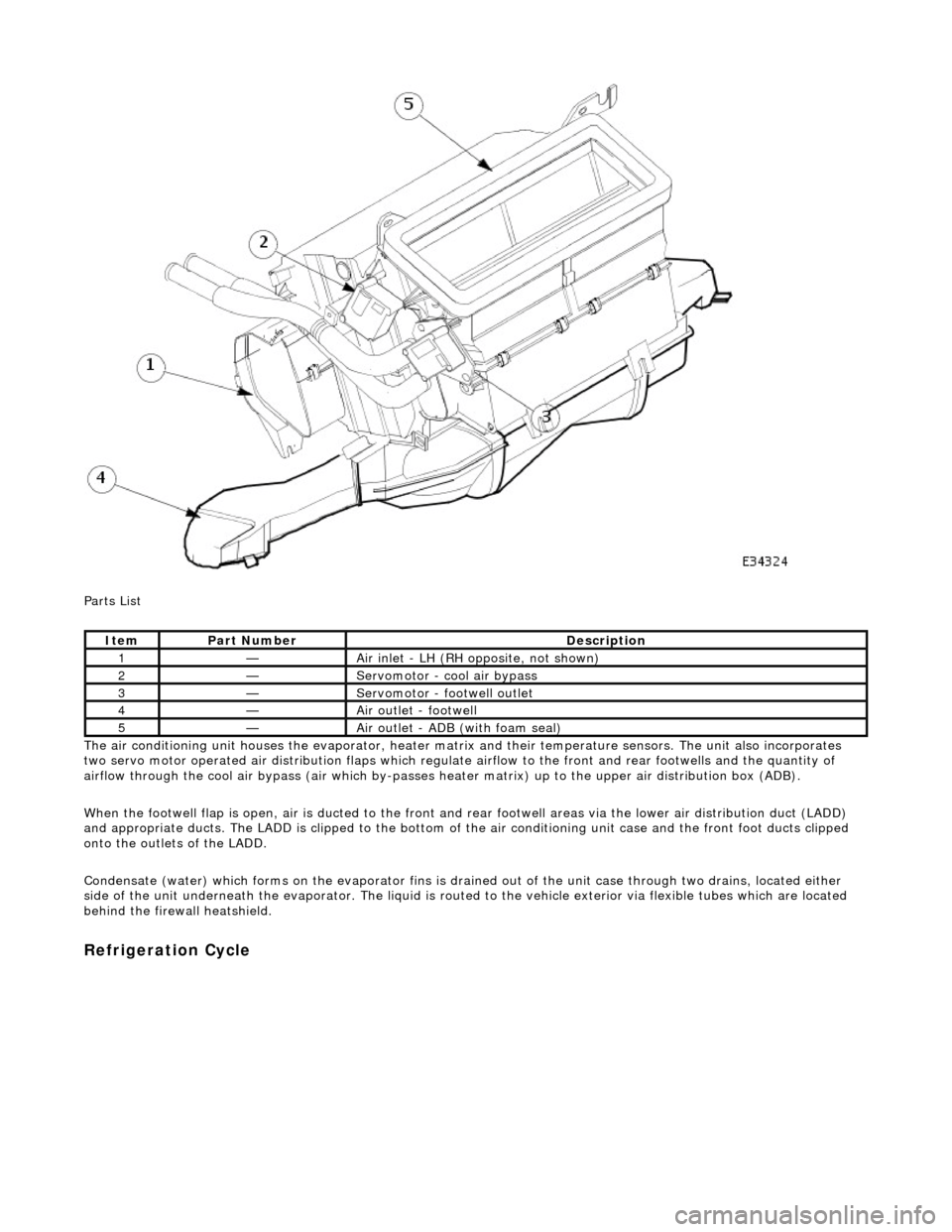
Parts List
The air conditioning unit houses the evap orator, heater matrix and their temperatur e sensors. The unit also incorporates
two servo motor operated air distribution flaps which regulate airflow to the front and rear footwells and the quantity of
airflow through the cool air bypass (air which by-passes he ater matrix) up to the upper air distribution box (ADB).
When the footwell flap is open, air is du cted to the front and rear footwell areas via the lower air distribution duct (LADD)
and appropriate ducts. The LADD is clipped to the bottom of the air conditioning unit case an d the front foot ducts clipped
onto the outlets of the LADD.
Condensate (water) which forms on the evaporator fins is drained out of the unit case through two drains, located either
side of the unit underneath the evaporator. The liquid is routed to the vehicle exterior via flexible tubes which are located
behind the firewa ll heatshield.
Refrigeration Cycle
ItemPart NumberDescription
1—Air inlet - LH (RH opposite, not shown)
2—Servomotor - cool air bypass
3—Servomotor - footwell outlet
4—Air outlet - footwell
5—Air outlet - ADB (with foam seal)
Page 1803 of 2490
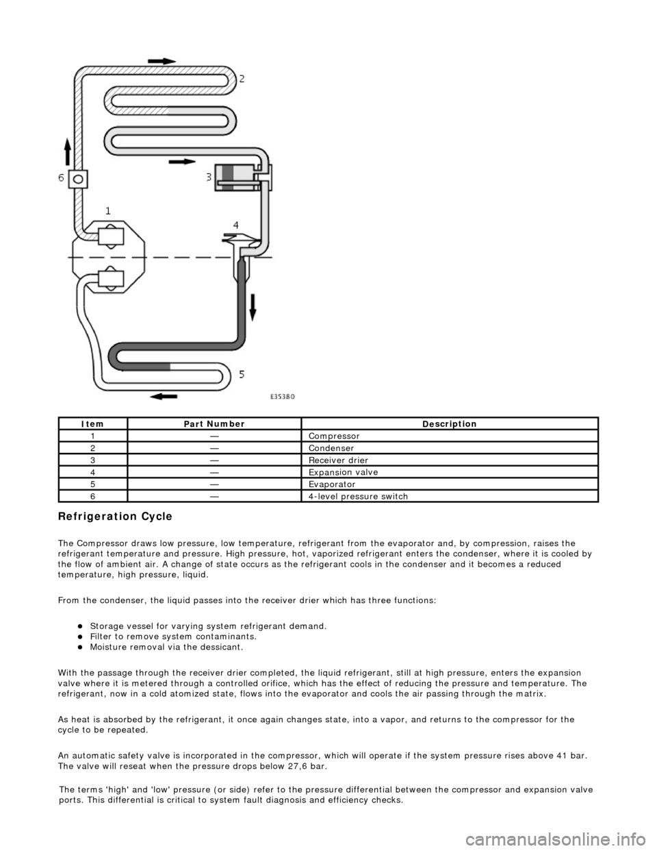
Refrigeration Cycle
The Compressor draws low pressure, lo
w te
mperature, refrigerant from the evaporat or and, by compression, raises the
refrigerant temperature and pressure. High pressure, hot, vaporized refr igerant enters the condenser, where it is cooled by
the flow of ambient air. A change of state occurs as the refrigerant cools in the condense r and it becomes a reduced
temperature, high pressure, liquid.
From the condenser, the liquid passes into the receiver drier which has three functions:
Storage vessel
for varying sy
stem refrigerant demand.
F
ilter to remove sy
stem contaminants.
Mo
isture removal via the dessicant.
With the passage through the receiver drie r completed, the liquid refrigerant, still at high pressure, enters the expansion
valve where it is metered through a contro lled orifice, which has the effect of reducing the pres sure and temperature. The
refrigerant, now in a cold atomized st ate, flows into the evaporator and cools the air passing through the matrix.
As heat is absorbed by the refrigerant, it once again changes state, into a vapor, and returns to the compressor for the
cycle to be repeated.
An automatic safety valve is incorporated in the compressor, which will operate if the system pressure rises above 41 bar.
The valve will reseat when the pressure drops below 27,6 bar.
It
em
Par
t Number
De
scription
1—Compre
ssor
2—Conden
ser
3—Re
ceiver drier
4—Expans
ion valve
5—Evaporator
6—4
-level pressure switch
The terms 'high' and 'low'
pressure (or si
de) refer to the pres sure differential betw een the compressor and expansion valve
ports. This differential is critical to sy stem fault diagnosis and efficiency checks.
Page 1822 of 2490
Ref #12 DEF (resumes the system on at the previous temperature setting).
Button (switch) logic
All buttons with an integral LED state lamp conform to the following operating logic.
When the state lamp is lit the relevant func tion is operational. From this condition, pressing the button will de-activate the
function, confirmed by the LED being de-energized and the pres ence of a single audible 'beep'. A single 'beep' will
accompany the state lamp to confirm function re-selection.
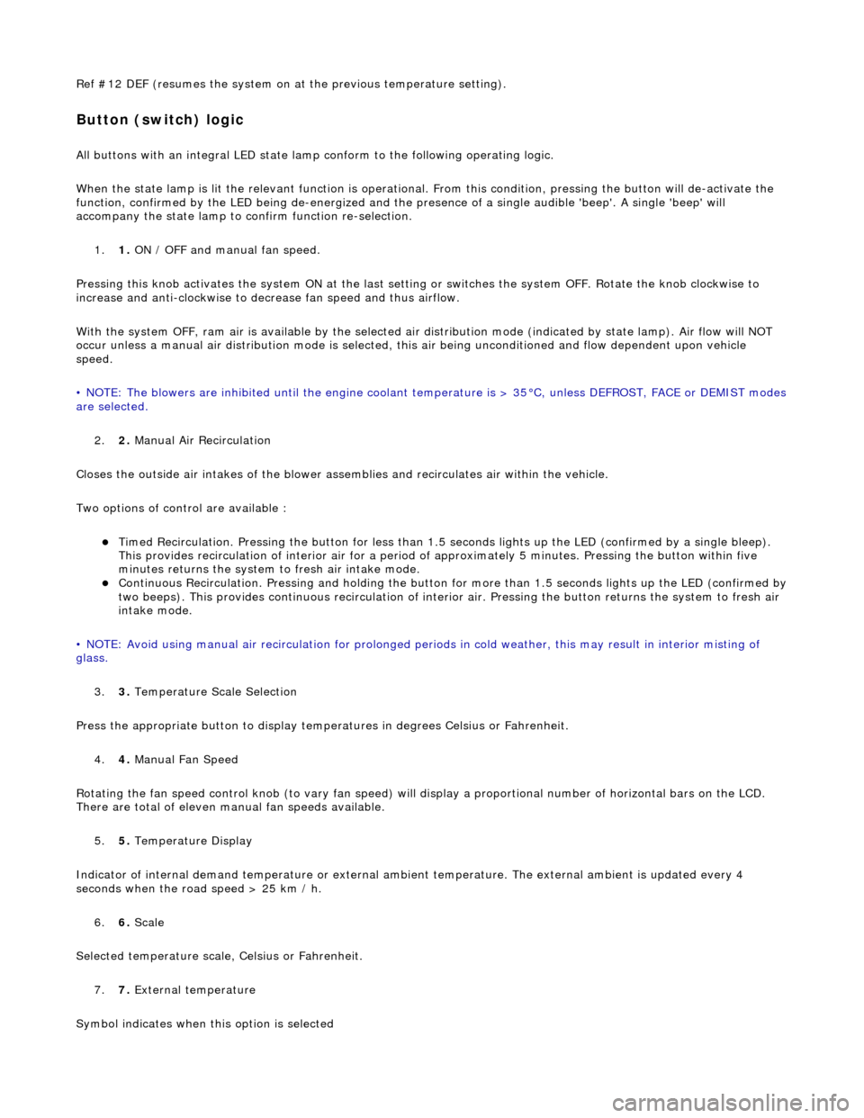
1. 1. ON / OFF and manual fan speed.
Pressing this knob activates the system ON at the last settin g or switches the system OFF. Rotate the knob clockwise to
increase and anti-clockwise to decrease fan speed and thus airflow.
With the system OFF, ram air is available by the selected air di stribution mode (indicated by state lamp). Air flow will NOT
occur unless a manual air distribution mo de is selected, this air being unconditioned and flow dependent upon vehicle
speed.
• NOTE: The blowers are inhibited until the engine coolant te mperature is > 35°C, unless DEFROST, FACE or DEMIST modes
are selected.
2. 2. Manual Air Recirculation
Closes the outside air intakes of the blower asse mblies and recirculates air within the vehicle.
Two options of control are available :
Timed Recirculation. Pressing the button for less than 1.5 seconds lights up the LED (confirmed by a single bleep).
This provides recirculation of interior air for a period of approximately 5 minutes. Pressing the button within five
minutes returns the system to fresh air intake mode.
Continuous Recirculation. Pressing and holding the button for more than 1.5 seconds lights up the LED (confirmed by two beeps). This provides continuous reci rculation of interior air. Pressing the button returns the system to fresh air
intake mode.
• NOTE: Avoid using manual air recirculatio n for prolonged periods in cold weather, this may result in interior misting of
glass.
3. 3. Temperature Scale Selection
Press the appropriate button to display temperatures in degrees Celsius or Fahrenheit.
4. 4. Manual Fan Speed
Rotating the fan speed control knob (to vary fan speed) will di splay a proportional number of horizontal bars on the LCD.
There are total of eleven manual fan speeds available.
5. 5. Temperature Display
Indicator of internal demand temperatur e or external ambient temperature. The external ambient is updated every 4
seconds when the road speed > 25 km / h.
6. 6. Scale
Selected temperature scale, Celsius or Fahrenheit.
7. 7. External temperature
Symbol indicates when this option is selected
Page 1825 of 2490
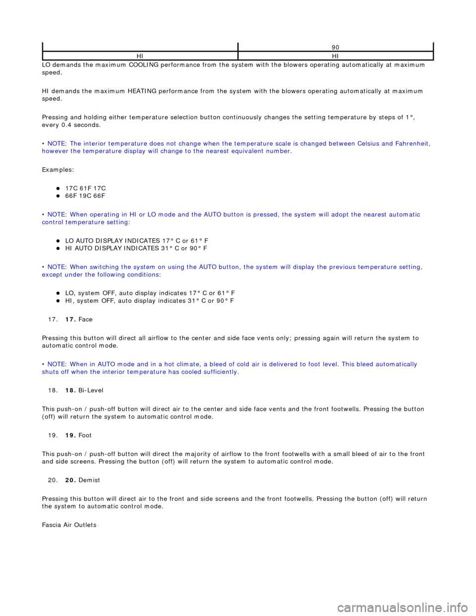
LO demands the maximum COOLING performance from the system with the blowers operating automatically at maximum
speed.
HI demands the maximum HEATING performance from the system with the blowers operating automatically at maximum
speed.
Pressing and holding either temperature selection button co ntinuously changes the setting temperature by steps of 1°,
every 0.4 seconds.
• NOTE: The interior temperature does not change when the temperature scale is changed between Celsius and Fahrenheit,
however the temperature display will chan ge to the nearest equivalent number.
Examples:
17C 61F 17C 66F 19C 66F
• NOTE: When operating in HI or LO mode and the AUTO butt on is pressed, the system will adopt the nearest automatic
control temperature setting:
LO AUTO DISPLAY INDICATES 17° C or 61° F HI AUTO DISPLAY INDICATES 31° C or 90° F
• NOTE: When switching the system on us ing the AUTO button, the system will display the previous temperature setting,
except under the following conditions:
LO, system OFF, auto display indicates 17° C or 61° F HI, system OFF, auto display indicates 31° C or 90° F
17. 17. Face
Pressing this button will direct all airflow to the center and side face vents only; pressing again will return the system to
automatic control mode.
• NOTE: When in AUTO mode and in a hot c limate, a bleed of cold air is delivered to foot level. This bleed automatically
shuts off when the inte rior temperature has cooled sufficiently.
18. 18. Bi-Level
This push-on / push-off button will direct air to the center and side face vent s and the front footwells. Pressing the button
(off) will return the system to automatic control mode.
19. 19. Foot
This push-on / push-off button will direct the majority of airflow to the front footwells with a small bleed of air to the fron t
and side screens. Pressing the button (off) will return the system to automatic control mode.
20. 20. Demist
Pressing this button will direct air to the front and side screens and the front foot wells. Pressing the button (off) will return
the system to automatic control mode.
Fascia Air Outlets
90
HIHI
Page 1826 of 2490
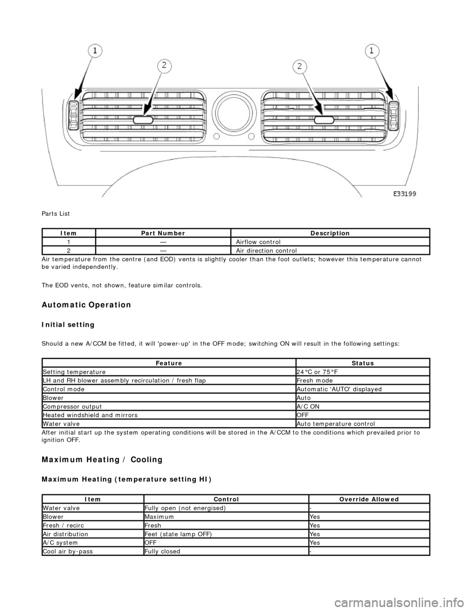
Parts List
Air temperature from the centre (and EOD) vents is slightly cooler than the foot outlets; however this temperature cannot
be varied independently.
The EOD vents, not shown, feature similar controls.
Automatic Operation
Initial setting
Should a new A/CCM be fitted, it will 'power-up' in the OFF mode; switching ON will result in the following settings:
After initial start up the system operating conditions will be st ored in the A/CCM to the conditions which prevailed prior to
ignition OFF.
Maximum Heating / Cooling
Maximum Heating (temperature setting HI)
ItemPart NumberDescription
1—Airflow control
2—Air direction control
FeatureStatus
Setting temperature24°C or 75°F
LH and RH blower assembly recirculation / fresh flapFresh mode
Control modeAutomatic 'AUTO' displayed
BlowerAuto
Compressor outputA/C ON
Heated windshield and mirrorsOFF
Water valveAuto temperature control
ItemControlOverride Allowed
Water valveFully open (not energised)-
BlowerMaximumYes
Fresh / recircFreshYes
Air distributionFeet (state lamp OFF)Yes
A/C systemOFFYes
Cool air by-passFully closed-
Page 1833 of 2490
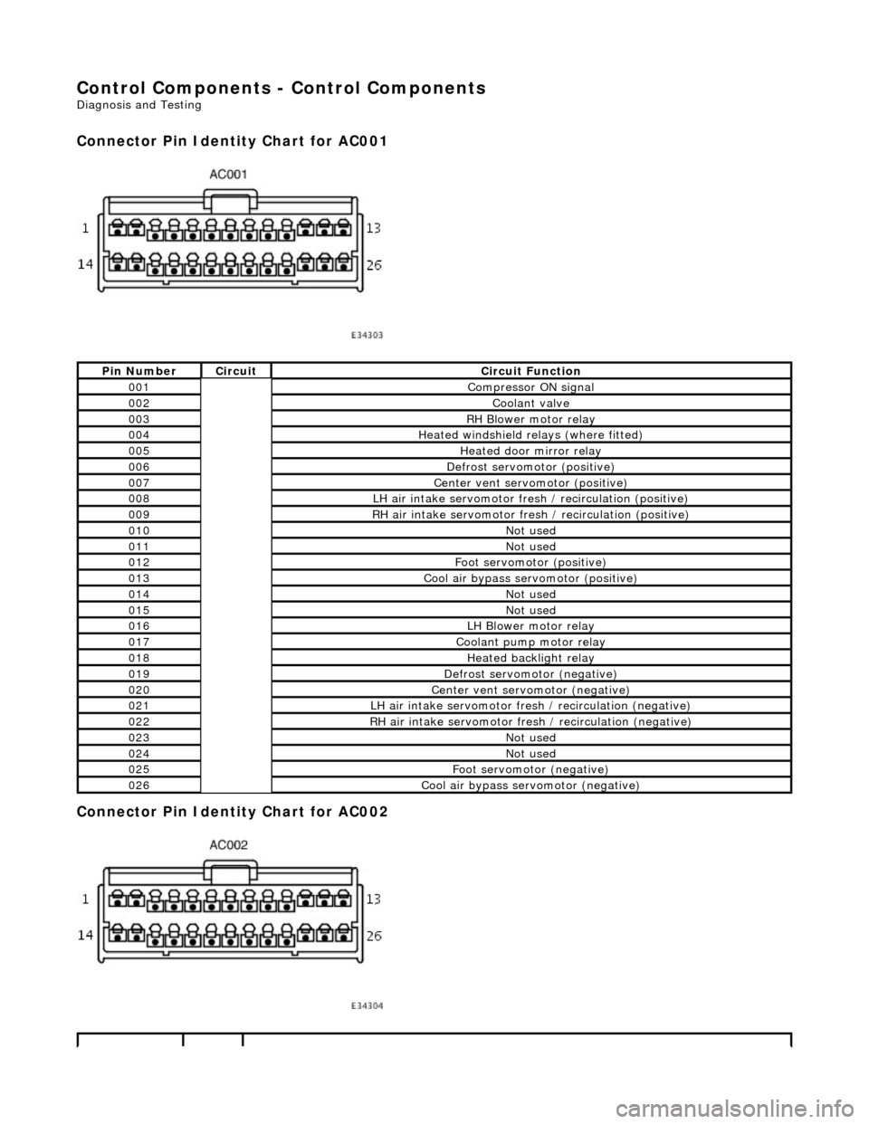
Control Components - Control Components
Diagnosis and Testing
Connector Pin Identity Chart for AC001
Connector Pin Identity Chart for AC002
Pin NumberCircuitCircuit Function
001Compressor ON signal
002Coolant valve
003RH Blower motor relay
004Heated windshield relays (where fitted)
005Heated door mirror relay
006Defrost servomotor (positive)
007Center vent servomotor (positive)
008LH air intake servomotor fre sh / recirculation (positive)
009RH air intake servomotor fresh / recirculation (positive)
010Not used
011Not used
012Foot servomotor (positive)
013Cool air bypass servomotor (positive)
014Not used
015Not used
016LH Blower motor relay
017Coolant pump motor relay
018Heated backlight relay
019Defrost servomotor (negative)
020Center vent servomotor (negative)
021LH air intake servomotor fresh / recirculation (negative)
022RH air intake servomotor fresh / recirculation (negative)
023Not used
024Not used
025Foot servomotor (negative)
026Cool air bypass servomotor (negative)
Page 1834 of 2490
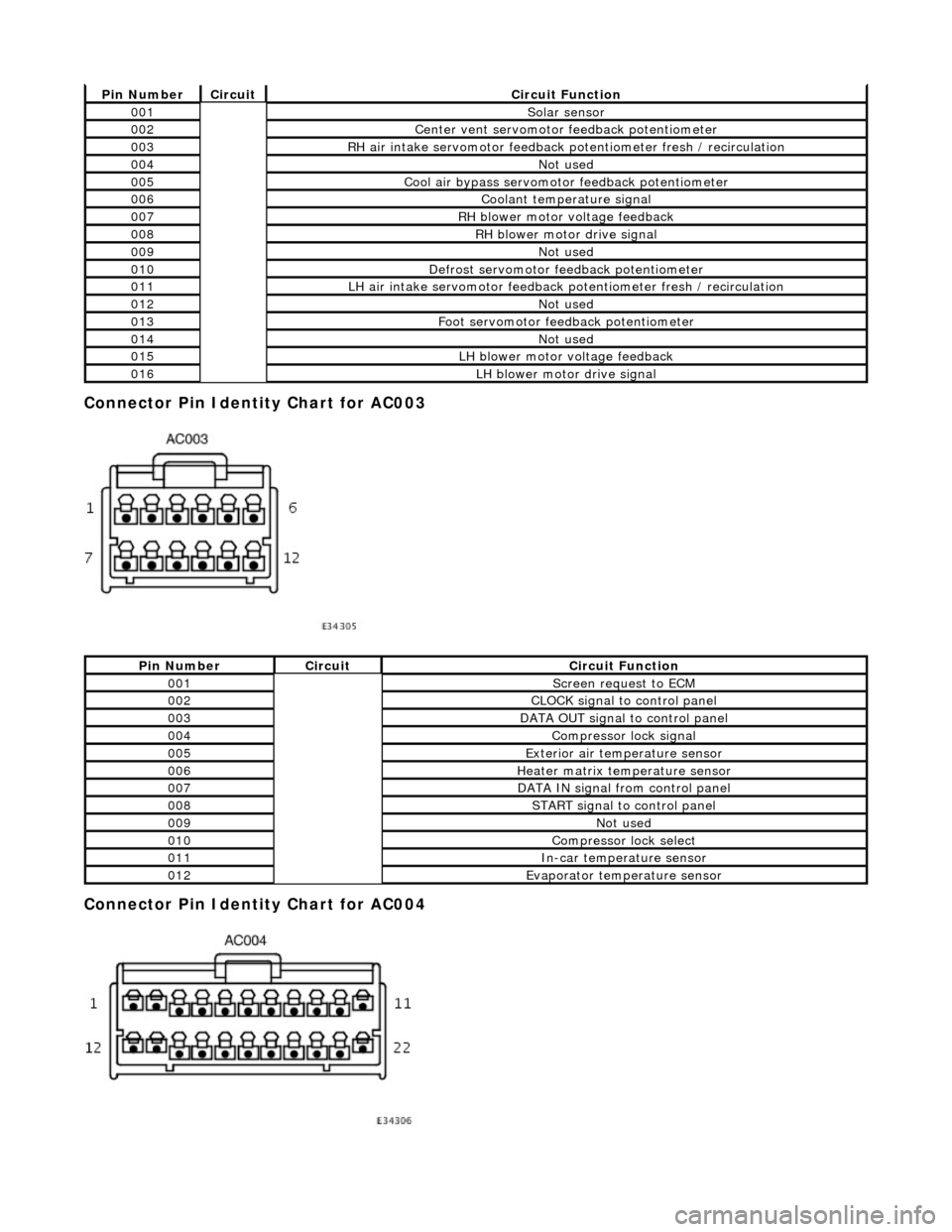
Connector Pin Identity Chart for AC003
Connector Pin Identity Chart for AC004
Pin NumberCircuitCircuit Function
001Solar sensor
002Center vent servomotor feedback potentiometer
003RH air intake servomotor feedback potentiometer fresh / recirculation
004Not used
005Cool air bypass servomotor feedback potentiometer
006Coolant temperature signal
007RH blower motor voltage feedback
008RH blower motor drive signal
009Not used
010Defrost servomotor feedback potentiometer
011LH air intake servomotor feedback potentiometer fresh / recirculation
012Not used
013Foot servomotor feedback potentiometer
014Not used
015LH blower motor voltage feedback
016LH blower motor drive signal
Pin NumberCircuitCircuit Function
001Screen request to ECM
002CLOCK signal to control panel
003DATA OUT signal to control panel
004Compressor lock signal
005Exterior air temperature sensor
006Heater matrix temperature sensor
007DATA IN signal from control panel
008START signal to control panel
009Not used
010Compressor lock select
011In-car temperature sensor
012Evaporator temperature sensor