1998 JAGUAR X308 camshaft
[x] Cancel search: camshaftPage 1039 of 2490
Fuel Charging and Controls
- Fuel Injector4.0L SC V8 - AJ26
Rem
oval and Installation
Remov
al
Installation
1.
Disconnect battery ground cabl e (IMPORTANT, see SRO 86.15.19
for further information).
2. WARNING: BEFORE PROCEEDING, IT IS ESSENTIAL THAT
THE WARNING NOTES GIVEN IN SECTION 100-00 (UNDER THE
HEADING 'SAFETY PRECAUTIONS') ARE READ AND UNDERSTOOD.
Depressurize fuel system; refer to 19.50.02.
3.
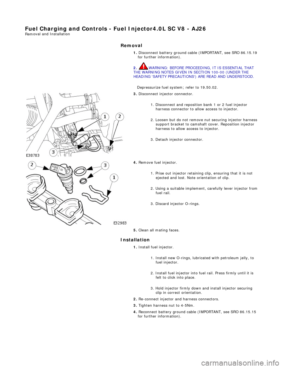
Disconnect injector connector.
1. Disconnect and reposition bank 1 or 2 fuel injector harness connector to allow access to injector.
2. Loosen but do not remove nut securing injector harness support bracket to camshaft cover. Reposition injector
harness to allow access to injector.
3. Detach injector connector.
4.
Remove fuel injector.
1. Prise out injector retaining clip, ensuring that it is not ejected and lost. Note orientation of clip.
2. Using a suitable implement, carefully lever injector from
fuel rail.
3. Discard injector O-rings.
5. Clean all mating faces.
1. Install fuel injector.
1. Install new O-rings, lubricat ed with petroleum jelly, to
fuel injector.
2. Install fuel injector into fuel rail. Press firmly until it is felt to click into place.
3. Hold injector firmly down and install injector securing clip in correct orientation.
2. Re-connect injector and harness connectors.
3. Tighten harness nut to 4-5Nm.
4. Reconnect battery ground cable (IMPORTANT, see SRO 86.15.15
for further information).
Page 1040 of 2490
Fuel Char
ging and Controls - Fu
el Injectors4.0L SC V8 - AJ26
Remo
val and Installation
Remov
a
l
Installation
1. Disc onne
ct battery ground cable (IMPORTANT, see SRO
86.15.19 for further information).
2. WARNING: BEFORE PROCEEDING, IT IS ESSENTIAL THAT
THE WARNING NOTES GIVEN IN SECTION 100-00 (UNDER THE
HEADING 'SAFETY PRECAUTIONS') ARE READ AND
UNDERSTOOD.
Depressurize fuel syst em; refer to 19.50.02.
3. Drain radiator coolant; refer to 2
6.10.01.
4. Remove air cleaner cover / inta ke assembly; refer 19.10.30.
5. Remove throttle body; refer to 19.70.04.
6. Remove throttle induction elbo w; refer to (SC) 19.70.28.
7. Remove exhaust gas re-circulation valve (EGR) if fitted; refer
to 17.45.01.
8. Remove supercharger outlet duct and gasket; refer to
18.50.16.
9. Remove coolant outlet pipe; refer to (SC) 26.31.08 .
10. Remove supercharger drive belt; refer to 18.50.08.
11. Remove supercharger assembly; refer to 18.50.15.
12. Remove bank 1 or 2 charge air cooler as required; refer to
18.50.18 and / or 18.50.19.
13 . Di
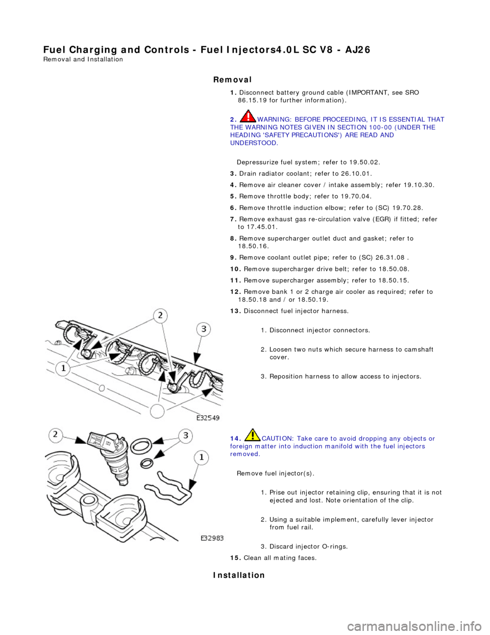
sconnect fuel injector harness.
1. Disconnect injector connectors.
2. Loosen two nuts which se cure harness to camshaft
cover.
3. Reposition harness to al low access to injectors.
14. CAUTI
ON: Take care to avoi
d dropping any objects or
foreign matter into induction ma nifold with the fuel injectors
removed.
Remove fuel injector(s). 1. Prise out injector retaining clip, ensuring that it is not
ejected and lost. Note orientation of the clip.
2. Using a suitable implemen t, carefully lever injector
from fuel rail.
3. Discard injector O-rings.
15 . Cle
an all mating faces.
Page 1041 of 2490
1.
Install
fuel injector(s).
1. Install new O-rings, lubricated with petroleum jelly, to
fuel injector.
2. Install fuel in jector into fuel rail. Press firmly until it is
felt to click into place.
3. Hold injector firmly down and fit injector securing clip
in the correct orientation.
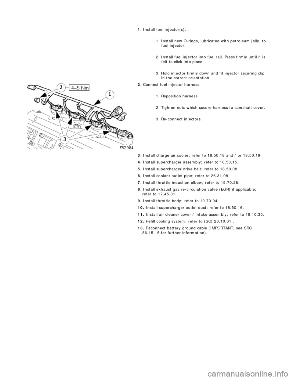
2. Conne
ct fuel injector harness.
1. Reposition harness.
2. Tighten nuts which secure harness to camshaft cover.
3. Re-connect injectors.
3. Install charge air c ooler; refer to 18.50.18 and / or 18.50.19.
4. Install supercharger asse mbly; refer to 18.50.15.
5. Install supercharger driv e belt; refer to 18.50.08.
6. Install coolant outlet pi pe; refer to 26.31.08.
7. Install throttle induction elbow; refer to 19.70.28.
8. Install exhaust gas re-circulation valve (EGR) if applicable;
refer to 17.45.01.
9. Install throttle body ; refer to 19.70.04.
10. Install supercharger outlet duct; refer to 18.50.16.
11. Install air cleaner cover / intake assembly; re fer to 19.10.30.
12. Refill cooling system; refer to (SC) 26.10.01 .
13. Reconnect battery ground cable (IMPORTANT, see SRO
86.15.15 for further information).
Page 1075 of 2490
F
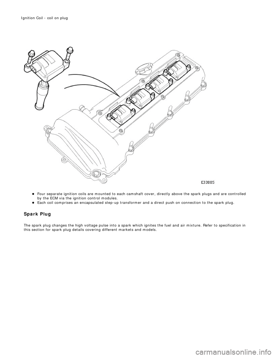
our separate ignition coils are mounte
d to each camshaft cover, directly above the spark plugs and are controlled
by the ECM via the ignition control modules.
Each
coil comprises an encapsulated step-up transformer
and a direct push on connection to the spark plug.
Spa
rk Plug
The spark plu
g changes the high voltage pulse into a spark whic
h ignites the fuel and air mixture. Refer to specification in
this section for spark plug details co vering different markets and models.
Igni
tion Coil - coil on plug
Page 1083 of 2490
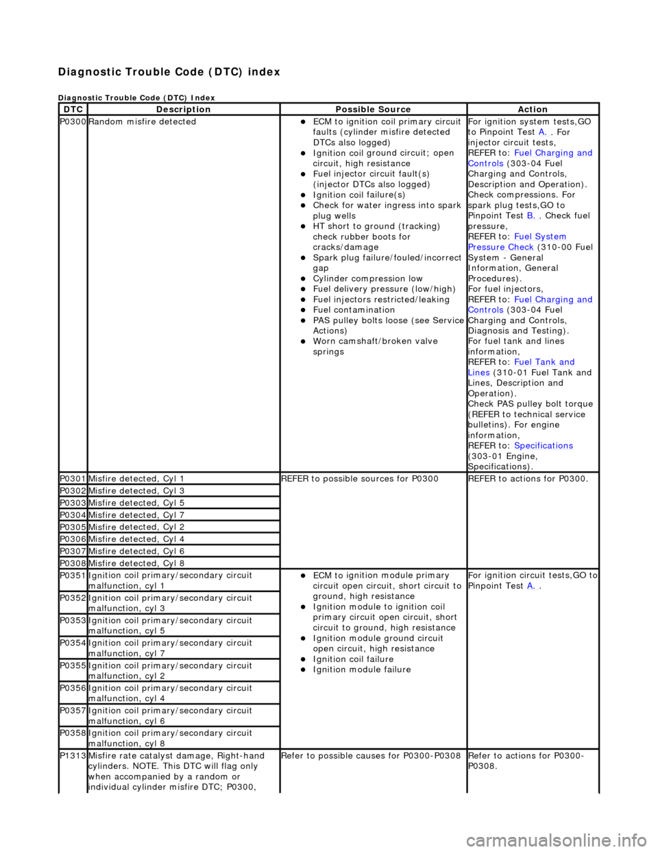
Diagnostic Trouble Code (D
TC) index
D
iagnostic Trouble Code (DTC) Index
DT
C
De
scription
Possib
le Source
Acti
on
P0300Ran
dom misfire detected
ECM t
o ignition coil primary circuit
faults (cylinder misfire detected
DTCs also logged)
Ignition coil
ground circuit; open
circuit, high resistance
F
uel injector circuit fault(s)
(injector DTCs also logged)
Ignition coil
failure(s)
Check f
or water ingress into spark
plug wells
HT sho
rt to ground (tracking)
check rubber boots for
cracks/damage
Spark plug
failure/fouled/incorrect
gap
Cy
linder compression low
F
uel delivery pressure (low/high)
F
uel injectors restricted/leaking
Fuel contamination
P
AS pulley bolts loose (see Service
Actions)
W
orn camshaft/broken valve
springs
For ign
ition system tests,GO
to Pinpoint Test A.
. For
inje
ctor circuit tests,
REFER to: Fuel Charging and
Controls (30
3-04 Fuel
Charging and Controls,
Description and Operation).
Check compressions. For
spark plug tests,GO to
Pinpoint Test B.
.
Check fuel
pressure,
REFER to: Fuel System
Pressure Check (31
0-00 Fuel
System - General
Information, General
Procedures).
For fuel injectors,
REFER to: Fuel Charging and
Controls (30
3-04 Fuel
Charging and Controls,
Diagnosis and Testing).
For fuel tank and lines
information,
REFER to: Fuel Tank and
Lin
es
(310-01 Fuel Tank and
Lines, Description and
Operation).
Check PAS pulley bolt torque
(REFER to technical service
bulletins). For engine
information,
REFER to: Specifications
(3
03-01 Engine,
Specifications).
P0301Misfire
detected, Cyl 1
R
EFER to possible sources for P0300
R
EFER to actions for P0300.
P0302Misfire
detected, Cyl 3
P0303Misfire
detected, Cyl 5
P0304Misfire
detected, Cyl 7
P0305Misfire
detected, Cyl 2
P0306Misfire
detected, Cyl 4
P0307Misfire
detected, Cyl 6
P0308Misfire
detected, Cyl 8
P0351Igni
tion coil primary/secondary circuit
malfunction, cyl 1
ECM to
ignition module primary
circuit open circuit, short circuit to
ground, high resistance
Igni
tion module to ignition coil
primary circuit open circuit, short
circuit to ground, high resistance
Ignition modu
le ground circuit
open circuit, hi gh resistance
Ignition coil
failure
Ignition modul
e failure
F
or ignition circuit tests,GO to
Pinpoint Test A.
.
P0352Igni
tion coil primary/secondary circuit
malfunction, cyl 3
P0353Igni
tion coil primary/secondary circuit
malfunction, cyl 5
P0354Igni
tion coil primary/secondary circuit
malfunction, cyl 7
P0355Igni
tion coil primary/secondary circuit
malfunction, cyl 2
P0356Igni
tion coil primary/secondary circuit
malfunction, cyl 4
P0357Igni
tion coil primary/secondary circuit
malfunction, cyl 6
P0358Igni
tion coil primary/secondary circuit
malfunction, cyl 8
P1313Misfire rate
catalyst damage, Right-hand
cylinders. NOTE. This DTC will flag only
when accompanied by a random or
individual cylinder misfire DTC; P0300,
R
efer to possible causes for P0300-P0308
R
efer to actions for P0300-
P0308.
Page 1107 of 2490
Intake Air Distribution and Filtering - Intake Air Distribution and Filtering
Description an
d Operation
I
ntake Air Distribution and Filtering - Normally Aspirated Vehicles
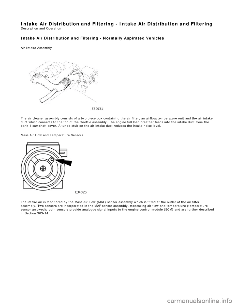
Air Intake Asse
mbly
The air cleaner assembly consists of a two piece box containing the air filter, an airflow/temperature unit and the air intake
duct which connects to the top of the throttle assembly. The en gine full load breather feeds into the intake duct from the
bank 1 camshaft cover. A tuned stub on the ai r intake duct reduces the intake noise level.
Mass Air Flow and Temperature Sensors
The intake air is monitored by the Mass Air Flow (MAF) sensor assembly which is fitted at the outlet of the air filter
assembly. Two sensors are incorporated in the MAF sensor assembly, measuring air flow and temperature (temperature
sensor arrowed); both sensors provide anal ogue signal inputs to the engine control module (ECM) and are further described
in Section 303-14.
Page 1111 of 2490
the
intake elbow provide connections for vacuum actuators and are also used to redirect emissions into the engine.
On the right-hand side of the elbow a la rge diameter pipe connects to the brake servo. The smaller pipe provides a vacuum
feed to the fuel rail pressure regulator and throttle cruise control system. On the le ft-hand side of the elbow the front pipe
supplies vacuum control for the evaporative emissions system valves.
Emissions from the engine part load breather (bank 2) and pu rged fuel vapor from the EVAP valve are drawn via a common
T piece into the left-hand side of the intake elbow. Re-cir culated exhaust gas enters the intake elbow via the EGR valve
which is mounted directly on the rear of the elbow : where the EGR system is not used, a blanking plate is fitted.
The fuel system, throttle and emission control system s are described more fully in the relevant sections.
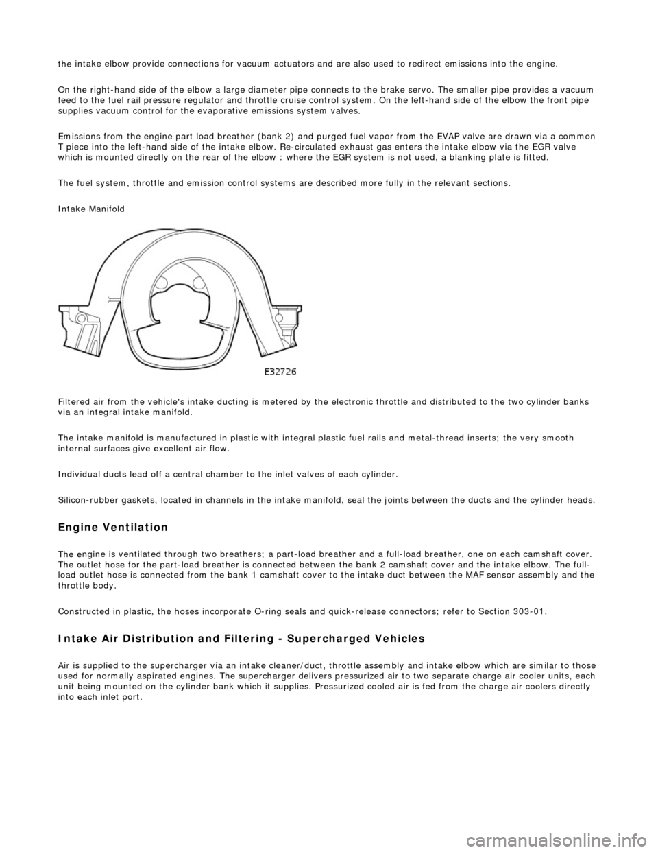
Intake Manifold
Filtered air from the vehicle's intake ducting is metered by th e electronic throttle and distributed to the two cylinder banks
via an integral intake manifold.
The intake manifold is manufactured in plastic with integral plastic fuel rails and metal-thread inserts; the very smooth
internal surfaces give excellent air flow.
Individual ducts lead off a central chamber to the inlet valves of each cylinder.
Silicon-rubber gaskets, loca ted in channels in the intake manifold, seal th e joints between the ducts and the cylinder heads.
Engine Ventilation
The e
ngine is ventilated through two brea
thers; a part-load breather and a full-load breather, one on each camshaft cover.
The outlet hose for the part-load breather is connected between the bank 2 camshaft cover and the intake elbow. The full-
load outlet hose is connected from the bank 1 camshaft cover to the intake duct between the MAF sensor assembly and the
throttle body.
Constructed in plastic, the hoses incorporate O-ring seal s and quick-release connectors; refer to Section 303-01.
I
ntake Air Distribution and Filtering - Supercharged Vehicles
Ai
r is supplied to the supercharger via an
intake cleaner/duct, throttle assembly and intake elbow which are similar to those
used for normally aspirated engines. The su percharger delivers pressurized air to two separate charge air cooler units, each
unit being mounted on the cy linder bank which it supplies. Pr essurized cooled air is fed from the charge air coolers directly
into each inlet port.
Page 1112 of 2490
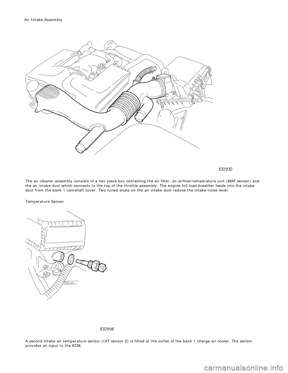
The air cleaner assembl y
consists of a tw
o piece box containing the ai r filter, an airflow/temperature unit (MAF sensor) and
the air intake duct which connects to the top of the throttle assembly. The engine full load breather feeds into the intake
duct from the bank 1 camshaft cover. Two tuned stubs on the air intake duct reduce the intake noise level.
Temperature Sensor
A second intake air temperature sensor (IAT sensor 2) is fitted at the outlet of the bank 1 charge air cooler. The sensor
provides an input to the ECM.
Air Intake Asse mbly