1998 JAGUAR X308 camshaft
[x] Cancel search: camshaftPage 1205 of 2490

TP se
nsor to ECM sensing circuits
('1' or '2') short circuit to high
voltage
TP sensor
failure
Throttl
e motor disconnected
Th
rottle motor to ECM drive circuits
short circuit or open circuit
Throttl
e motor failure
Throttl
e assembly failure
Test
K. . F
or throttle motor circuit
tests,GO to Pinpoint Test T.
. For
throttle body i
nformation,
REFER to Section 303
-04
Fuel
Charging and Con
trols
.
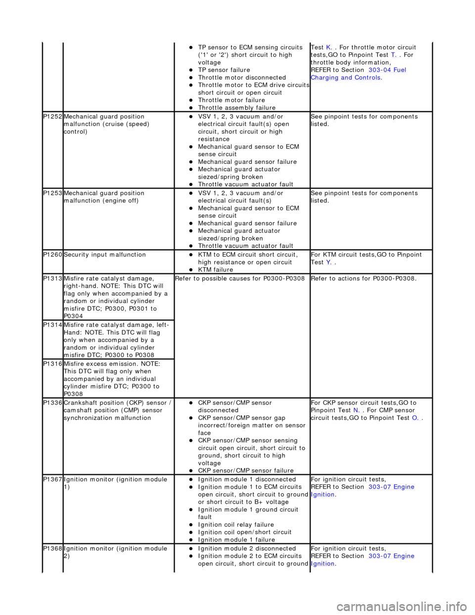
P1252Mec
hanical gu
ard position
malfunction (cruise (speed)
control)
VSV 1, 2, 3 v
acuum and/or
electrical circuit fault(s) open
circuit, short circuit or high
resistance
Mechanica
l guard sensor to ECM
sense circuit
Mechanica
l guard sensor failure
Mechanica
l guard actuator
siezed/spring broken
Throttl
e vacuum actuator fault
Se
e pinpoint tests for components
listed.
P1253Mec
hanical gu
ard position
malfunction (engine off)
VSV 1, 2, 3 v
acuum and/or
electrical circuit fault(s)
Mechanica
l guard sensor to ECM
sense circuit
Mechanica
l guard sensor failure
Mechanica
l guard actuator
siezed/spring broken
Throttl
e vacuum actuator fault
Se
e pinpoint tests for components
listed.
P1260Se
curity input malfunction
K
TM to ECM circuit short circuit,
high resistance or open circuit
KTM failu
re
F
or KTM circuit tests,GO to Pinpoint
Test Y.
.
P1313M
isfire rate catalyst damage,
right-hand. NOTE: This DTC will
flag only when accompanied by a
random or individual cylinder
misfire DTC; P0300, P0301 to
P0304
R
efer to possible causes for P0300-P0308
R
efer to actions for P0300-P0308.
P1314Mi
sfire rate catalyst damage, left-
Hand: NOTE. This DTC will flag
only when accompanied by a
random or individual cylinder
misfire DTC; P0300 to P0308
P1316M
isfire excess emission. NOTE:
This DTC will flag only when
accompanied by an individual
cylinder misfire DTC; P0300 to
P0308
P1336Cranksh
aft position
(CKP) sensor /
camshaft position (CMP) sensor
synchronization malfunction
CKP s
ensor/CMP sensor
disconnected
CKP sensor/CM
P sensor gap
incorrect/foreign matter on sensor
face
CKP s
ensor/CMP sensor sensing
circuit open circuit, short circuit to
ground, short circuit to high
voltage
CKP s
ensor/CMP sensor failure
F
or CKP sensor circ
uit tests,GO to
Pinpoint Test N.
. For CM
P sensor
circuit tests,GO to Pinpoint Test O.
.
P1367Ignit
ion monitor (ignition module
1)
Ignition modu
le
1 disconnected
Ignition modul
e 1 to ECM circuits
open circuit, short circuit to ground
or short circuit to B+ voltage
Ignition modul
e 1 ground circuit
fault
Ignition coil
relay failure
Ignition coil
open/short circuit
Ignition modul
e 1 failure
F
or ignition circuit tests,
REFER to Section 303
-07
Engine
Ignition.
P1368Ignit
ion monitor (ignition module
2)
Ignition modu
le
2 disconnected
Ignition modul
e 2 to ECM circuits
open circuit, short circuit to ground
F
or ignition circuit tests,
REFER to Section 303
-07
Engine
Ignition.
Page 1217 of 2490

REF
ER to
Crankshaft Position (CKP) Sensor
in this section.
Reconnect the sensor. CLEAR the DTCs. TE ST the system for normal operation.
N
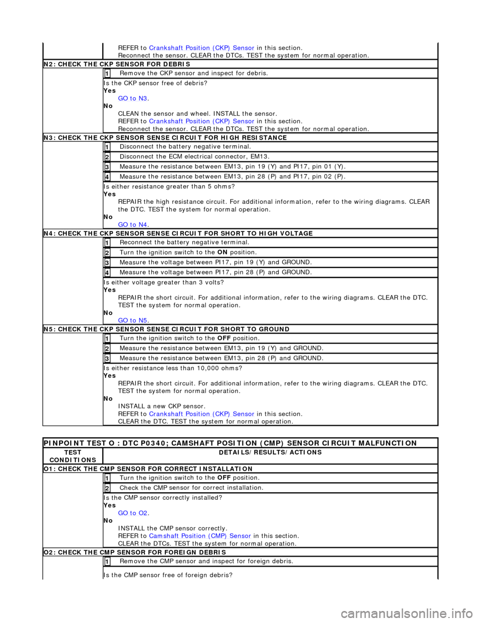
2: CHECK THE CKP SENSOR FOR DEBRIS
Re
move the CKP sensor
and inspect for debris.
1
Is the CKP sensor free of
debris?
Yes GO to N3
.
No
CLEAN the sensor and whee l. INSTALL the sensor.
REFER to Crankshaft Position (CKP) Sensor
in this section.
Reconnect the sensor. CLEAR the DTCs. TE ST the system for normal operation.
N
3: CHECK THE CKP SENSOR SENSE CIRCUIT FOR HIGH RESISTANCE
Di
sconnect the battery negative terminal.
1
D
isconnect the ECM electrical connector, EM13.
2
Me
asure the resistance between EM13, pin 19 (Y) and PI17, pin 01 (Y).
3
Meas
ure the resistance between EM13, pin 28 (P) and PI17, pin 02 (P).
4
Is either resi
stance
greater than 5 ohms?
Yes REPAIR the high resistance circui t. For additional information, refer to the wiring diagrams. CLEAR
the DTC. TEST the system for normal operation.
No GO to N4
.
N
4: CHECK THE CKP SENSOR SENSE CI
RCUIT FOR SHORT TO HIGH VOLTAGE
R
econnect the battery negative terminal.
1
Turn the ignition swi
tch to the ON
position.
2
Meas
ure the voltage between PI17, pin 19 (Y) and GROUND.
3
M
easure the voltage between PI17, pin 28 (P) and GROUND.
4
Is ei
ther voltage greater than 3 volts?
Yes REPAIR the short circuit. For addi tional information, refer to the wiring diagrams. CLEAR the DTC.
TEST the system for normal operation.
No GO to N5
.
N
5: CHECK THE CKP SENSOR SENSE CIRCUIT FOR SHORT TO GROUND
Turn the ignition swi
tch to the OFF
position.
1
Meas
ure the resistance between EM13, pin 19 (Y) and GROUND.
2
Meas
ure the resistance between EM13, pin 28 (P) and GROUND.
3
Is either resi
stance
less than 10,000 ohms?
Yes REPAIR the short circuit. For addi tional information, refer to the wiring diagrams. CLEAR the DTC.
TEST the system for normal operation.
No INSTALL a new CKP sensor.
REFER to Crankshaft Position (CKP) Sensor
in this section.
CLEAR the DTC. TEST the system for normal operation.
P
INPOINT TEST O : DTC P0340;
CAMSHAFT POSITION (CMP) SENSOR CIRCUIT MALFUNCTION
TE
ST
CONDITIONS
D
ETAILS/RESULTS/ACTIONS
O1: CHECK THE CM
P SENSOR FOR CORRECT INSTALLATION
Turn the ignition swi
tch to the OFF
position.
1
Check the CMP
sensor fo
r correct installation.
2
Is th
e CMP sensor correctly installed?
Yes GO to O2
.
No
INSTALL the CMP sensor correctly.
REFER to Camshaft Position (CMP) Sensor
in this section.
CLEAR the DTCs. TEST the system for normal operation.
O2: CHECK THE CM
P SENSOR FOR FOREIGN DEBRIS
Re
move the CMP sensor and
inspect for foreign debris.
1
Is the CMP sensor free of
foreign debris?
Page 1218 of 2490

Yes
GO to N3.
No
CLEAN th
e sensor and whee
l. INSTALL the sensor.
REFER to Camshaft Position (CMP) Sensor
in this
section.
CLEAR the DTCs. TEST the system for normal operation.
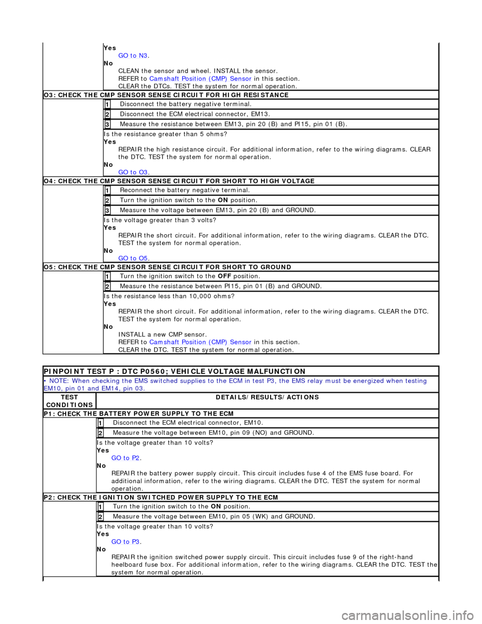
O3: CHECK THE CM P SEN
SOR SENS
E CIRCUIT FOR HIGH RESISTANCE
Disc
onnect the battery negative terminal.
1
D
i
sconnect the ECM electrical connector, EM13.
2
Meas
ure t
he resistance between EM13, pin 20 (B) and PI15, pin 01 (B).
3
Is the res
istance greater than 5 ohms?
Yes REPAIR the high resistance circui t. For additional information, refer to the wiring diagrams. CLEAR
the DTC. TEST the system for normal operation.
No GO to O3
.
O4: CHECK THE CM P SEN
SOR SENSE CI
RCUIT FOR SHORT TO HIGH VOLTAGE
Re
connect the battery negative terminal.
1
Turn the ignition swi
t
ch to the ON
position.
2
Me
asure the voltage between EM13, pin 20 (B) and GROUND.
3
Is th
e volt
age greater than 3 volts?
Yes REPAIR the short circuit. For addi tional information, refer to the wiring diagrams. CLEAR the DTC.
TEST the system for normal operation.
No GO to O5
.
O5: CH ECK THE CM
P SENSOR SENSE CIRCUIT FOR SHORT TO GROUND
Turn the ignition swi
t
ch to the OFF
position.
1
Me
asure the resistance between PI15, pin 01 (B) and GROUND.
2
Is
t
he resistance less than 10,000 ohms?
Yes REPAIR the short circuit. For addi tional information, refer to the wiring diagrams. CLEAR the DTC.
TEST the system for normal operation.
No INSTALL a new CMP sensor.
REFER to Camshaft Position (CMP) Sensor
in this
section.
CLEAR the DTC. TEST the system for normal operation.
P I
NPOINT TEST P : DTC P0560; VEHICLE VOLTAGE MALFUNCTION
•
NOTE
: When checking the EMS switched supplies to the ECM
in test P3, the EMS relay must be energized when testing
EM10, pin 01 and EM14, pin 03.
TE S
T
CONDITIONS
D E
TAILS/RESULTS/ACTIONS
P1: CHECK
THE BATTERY POWER SUPPLY TO THE ECM
D
i
sconnect the ECM electrical connector, EM10.
1
Measure the
voltage between EM 10,
pin 09 (NO) and GROUND.
2
Is the vol
t
age greater than 10 volts?
Yes GO to P2
.
No
REPAIR th
e battery power supply circ
uit. This circuit includes fuse 4 of the EMS fuse board. For
additional information, refer to the wiring diagrams. CLEAR the DT C. TEST the system for normal
operation.
P2: CHECK
THE IGNITION SWITCH
ED POWER SUPPLY TO THE ECM
Turn the ignition swit
ch to the
ON position.
1
Meas
ure t
he voltage between EM10, pin 05 (WK) and GROUND.
2
Is the vol
t
age greater than 10 volts?
Yes GO to P3
.
No
REP
AIR the ignition switched power supply circuit. This circuit includes fuse 9 of the right-hand
heelboard fuse box. For a dditional information, refer to the wiri ng diagrams. CLEAR the DTC. TEST the
system for normal operation.
Page 1258 of 2490

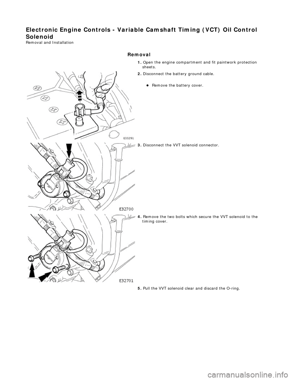
El
ectronic Engine Controls - Variable
Camshaft Timing (VCT) Oil Control
Solenoid
Re mo
val and Installation
Remova
l
1.
Op
en the engine compartment and fit paintwork protection
sheets.
2. Disc
onnect the batt
ery ground cable.
Re
move the battery cover.
3. Disc
onnect the VVT solenoid connector.
4. Re
move the two bolts which secure the VVT solenoid to the
timing cover.
5. Pull the VVT solenoid clear and discard the O-ring.