1998 JAGUAR X308 window
[x] Cancel search: windowPage 1981 of 2490
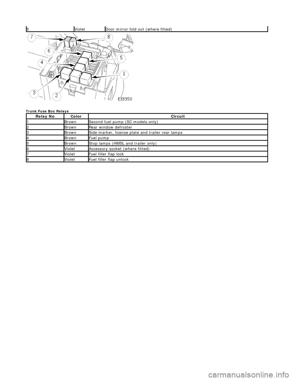
Trunk Fuse Box Relays
5VioletDoor mirror fold out (where fitted)
Relay NoColorCircuit
1BrownSecond fuel pump (SC models only)
2BrownRear window defroster
3BrownSide marker, license plate and trailer rear lamps
4BrownFuel pump
5BrownStop lamps (HMSL and trailer only)
6VioletAccessory socket (where fitted)
7VioletFuel filler flap lock
8VioletFuel filler flap unlock
Page 2002 of 2490
Repair Procedure
• CAUTIONS: Do not use crimping pliers, insulation strippers, butt splice connectors, heat sh rink sleeves or pre-terminated wiring
harness(s) that are not supplied with the Jagu ar wiring harness repair kit. Each part has been designed to be used only with
the other parts in this wiri ng harness repair kit.
Where the repair procedure indicates that a glue lined heat shrink sleeve should be applied, apply sufficient heat to
the glue lined heat shrink to melt the glue in order to provide a water tight seal. Do not
over heat the glue lined heat shrink sleeve so that the wiring harness insulation becomes damaged.
It is not correct to make more than five repair joints on the wiring harness to any electrical connector and if more damage is
found at the same electrical connector then a new wiring harness must be installed.
Remove the faulty terminal from the elec trical connector using the extractor tool and correct tip. Make sure that any
anti-backout device is released befo re trying to remove the terminal.
CAUTION: : A number of electrical connector terminals ar e gold plated or gold flashed. When defective, they
must be installed with a gold pre-terminated wiring harnes s(s) from the wiring harness repair kit. It is not always
easy to identify the female as gold but the male pins are visually easier, therefore always check both male and
female terminals to identify those which are gold. Under no circumstances are gold and tin terminals to be mixed as
this will lead to early failur e of the electrical contact.
• NOTE: Never use a harness lead with a smalle r diameter than the original harness lead.
Select the correct size and ty pe of pre-terminated wiring harness and butt splice connector from the wiring harness
repair kit.
Using the wire cutter on the stripping tool, cut the pre-terminated wiring harness and the harness cable to the
required length.
• NOTE: See illustration: Stripping Insulation
From the Relationship Table, find the correct length of insulation to be stripped from the pre-terminated wiring
harness and set the adjustable cable length stop to the correct length. Place the pre-terminated wiring harness in
the wire stripper and remove the insulation.
Put the cable identification sleeve(s) on to the wiring harness with the main cable colour nearest to the terminal. During this next step do not overtighten. Place the selected butt splice connector in the crimping tool, matching the
aperture and the butt connector colours. Make sure that the window indentation in the butt connector is resting over
the guide bar on the lower jaw. Partially close the grip until the butt connec tor is securely held in the aperture. This
will give support to the butt conn ector while the pre-terminated wiring harness is inserted into it.
• NOTE: See illustration: Spice Correctly Located
Insert the pre-terminated wiring harnes s into the butt connector and make sure that the wire is against the wire
stop. Close the grip firmly, crimping the lead to the butt connector. When the handles have been completely closed
the butt connector will be fre ed from the tool as the handles are released. If the handles have not been completely
closed then the jaws will hold the butt connector and it cannot be removed from the tool until the crimp is fully made
by closing the handles completely. Make sure that the harness cable has been squarely cut and the correct length of insulation removed. If more than
one splice is needed the butt connectors must be not be crimped to the wiring harness at the same distance from
the connector. The splices must be staggered to prevent a bulk of splices in the same area of the wiring harness.
It is preferable to cover the butt splice joint with heat shrink sleeve. This is desirable not essential, except where the
electrical connector is a sealed electrical connector. Use the smaller diameter sleeve for red and blue pre-terminated
wiring harness(s) and the large diameter sleeve for the yellow pre-terminated wiring harnes s(s). It is advisable to
place the heat shrink over the completed joint but in some instances the sleeve will not pass over the terminal.
Check, and if required, place the correct size sleeve onto the harness cable or pre-terminated wiring harness before
crimping the butt splice to the wiring harness.
Place the harness cable into the butt splice with the spli ce window over the guide bar. Make sure that the cable
harness wire is agains t the stop in the butt splice, crimp the butt splice connector to the wiring harness.
Gently pull the harness cables each side of the butt sp lice to make sure that a secure joint has been made.
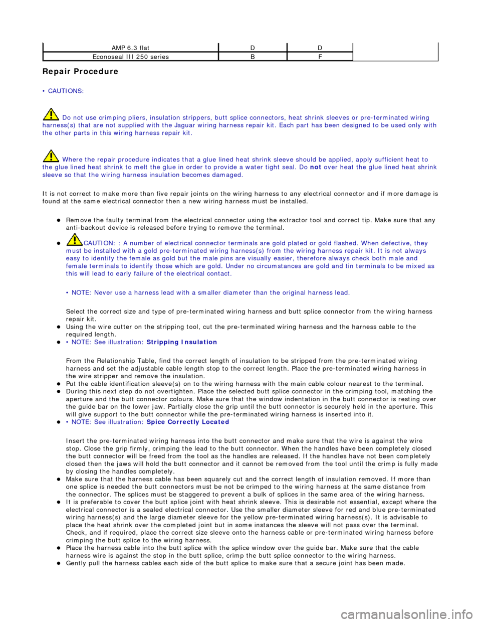
AMP 6.3 flatDD
Econoseal III 250 seriesBF
Page 2009 of 2490
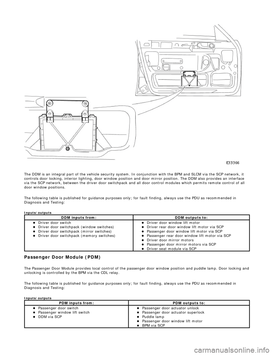
The DDM is an integral part of the vehi cle security system. In conjunction with the BPM and SLCM via the SCP network, it
controls door locking, interior lighting, door window position and door mirror position. The DDM also provides an interface
via the SCP network, between the driver door switchpack and all door control modules which permits remote control of all
door window positions.
The following table is published for guidance purp oses only; for fault finding, always use the PDU as recommended in
Diagnosis and Testing:
Inputs/outputs
Passenger Door Module (PDM)
The Passenger Door Module provides local control of the pass enger door window position and puddle lamp. Door locking and unlocking is controlled by the BPM via the CDL relay.
The following table is published for guidance purp oses only; for fault finding, always use the PDU as recommended in
Diagnosis and Testing:
Inputs/outputs
DDM inputs from:DDM outputs to:
Driver door switch Driver door switchpack (window switches) Driver door switchpack (mirror switches) Driver door switchpack (memory switches)
Driver door window lift motor Driver rear door window lift motor via SCP Passenger door window lift motor via SCP Passenger rear door window lift motor via SCP Driver door mirror motors Passenger door mirror motors via SCP Driver seat module via SCP
PDM inputs from:PDM outputs to:
Passenger door switch Passenger window lift switch DDM via SCP
Passenger door actuator unlock Passenger door actuator superlock Puddle lamp Passenger door window lift motor BPM via SCP
Page 2010 of 2490
Driver Rear Door Module (DRDM)
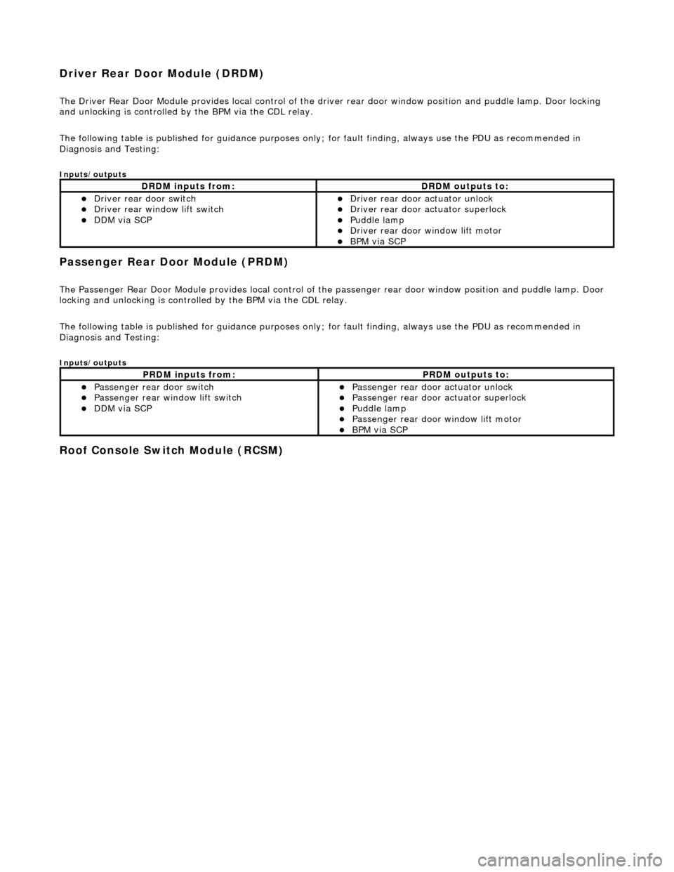
The Driver Rear Door Module provides local control of the driver rear door window position and puddle lamp. Door locking
and unlocking is controlled by the BPM via the CDL relay.
The following table is published for guidance purp oses only; for fault finding, always use the PDU as recommended in
Diagnosis and Testing:
Inputs/outputs
Passenger Rear Door Module (PRDM)
The Passenger Rear Door Module provides local control of th e passenger rear door window position and puddle lamp. Door
locking and unlocking is controlled by the BPM via the CDL relay.
The following table is published for guidance purp oses only; for fault finding, always use the PDU as recommended in
Diagnosis and Testing:
Inputs/outputs
Roof Console Switch Module (RCSM)
DRDM inputs from:DRDM outputs to:
Driver rear door switch Driver rear window lift switch DDM via SCP
Driver rear door actuator unlock Driver rear door actuator superlock Puddle lamp Driver rear door window lift motor BPM via SCP
PRDM inputs from:PRDM outputs to:
Passenger rear door switch Passenger rear window lift switch DDM via SCP
Passenger rear door actuator unlock Passenger rear door actuator superlock Puddle lamp Passenger rear door window lift motor BPM via SCP
Page 2034 of 2490
Body Closures - Body Closures
Description and Operation
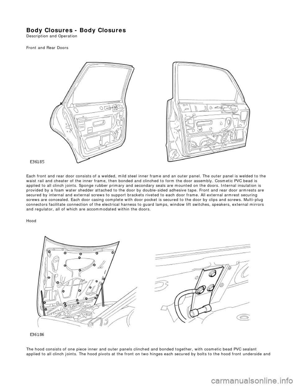
Front and Rear Doors
Each front and rear door consists of a welded, mild steel inner frame and an outer panel. The outer panel is welded to the
waist rail and cheater of the inner frame, then bonded and clinched to fo rm the door assembly. Cosmetic PVC bead is
applied to all clinch joints. Sponge rubber primary and secondary seals are mo unted on the doors. Internal insulation is
provided by a foam water shedder attached to the door by double-sided adhesive tape. Front and rear door armrests are
secured by internal and external screws to support brackets riveted to each door frame . All external armrest securing
screws are concealed. Each door casing complete with door po cket is secured to the door by clips and screws. Multi-plug
connectors facilitate connection of the electrical harness to guard lamps, window lift switches, speakers, external mirrors
and regulator, all of which are accommodated within the doors.
Hood
The hood consists of one piece inner an d outer panels clinched and bonded toge ther, with cosmetic bead PVC sealant
applied to all clinch joints. The hood pivo ts at the front on two hinges each secured by bolts to the hood front underside and
Page 2061 of 2490
Interior Trim and Ornamentation - Door Window Control Switch Finish
Panel
Removal and Installation
Removal
Installation
1.
Remove door casing veneer panel. Refer to 76.47.11.
2. Remove door casing. Refer to 76.34.01.
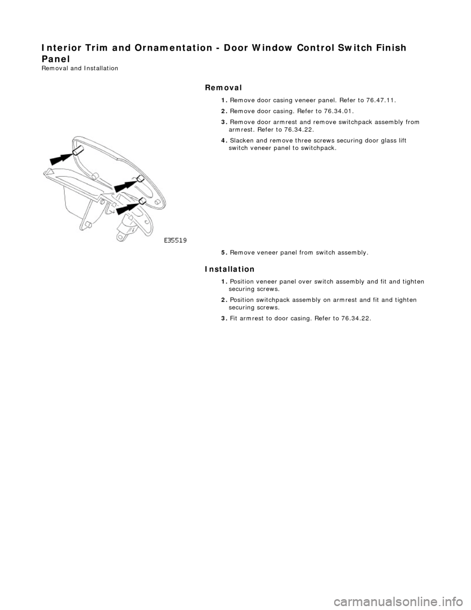
3. Remove door armrest and remo ve switchpack assembly from
armrest. Refer to 76.34.22.
4. Slacken and remove th ree screws securing door glass lift
switch veneer panel to switchpack.
5. Remove veneer panel from switch assembly.
1. Position veneer panel over swit ch assembly and fit and tighten
securing screws.
2. Position switchpack assembly on armrest and fit and tighten
securing screws.
3. Fit armrest to door casing. Refer to 76.34.22.
Page 2076 of 2490
Interior Trim and Ornamentation - Headliner
Removal and Installation
Removal
Vehicles with roof opening panel
All vehicles
1. Remove the roof opening panel trim.
For additional information, refer to: Roof Opening Panel Trim
(501-17 Roof Opening Panel, Removal and Installation).
2. Remove both C-pill ar trim panels.
For additional information, refer to: C
-Pillar Trim Panel (501-05
Interior Trim and Ornamentatio n, Removal and Installation).
3. Remove both A-pill ar trim panels.
For additional information, refer to: A
-Pillar Trim Panel (501-05
Interior Trim and Ornamentatio n, Removal and Installation).
4. Remove the overhead console.
For additional information, refer to: Overhead Console
(501-12
Instrument Panel and Console, Removal and Installation).
5. Remove the rear window glass.
For additional information, refer to: Rear Window Glass
(501-
11 Glass, Frames and Mechanis ms, Removal and Installation).
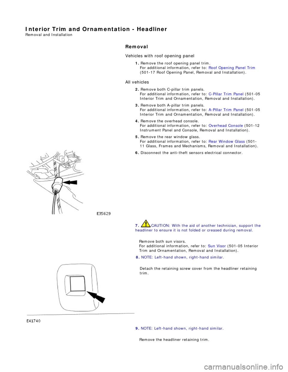
6. Disconnect the anti-theft se nsors electrical connector.
7. CAUTION: With the aid of an other technician, support the
headliner to ensure it is not folded or creased during removal.
Remove both sun visors.
For additional information, refer to: Sun Visor
(501-05 Interior
Trim and Ornamentation, Re moval and Installation).
8. NOTE: Left-hand shown, right-hand similar.
Detach the retaining screw cove r from the headliner retaining
trim.
9. NOTE: Left-hand shown, right-hand similar.
Remove the headline r retaining trim.
Page 2079 of 2490
Vehicles with roof opening panel
7. Install both sun visors.
For additional information, refer to: Sun Visor (501-05 Interior
Trim and Ornamentation, Re moval and Installation).
8. Install the rear window glass.
For additional information, refer to: Rear Window Glass
(501-
11 Glass, Frames and Mechanis ms, Removal and Installation).
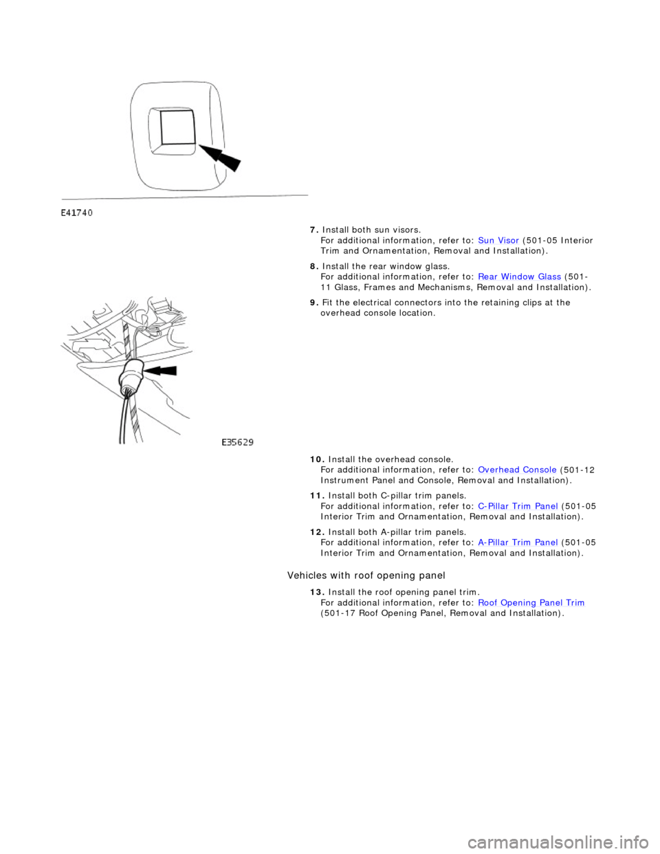
9. Fit the electrical connectors into the retaining clips at the
overhead console location.
10. Install the overhead console.
For additional information, refer to: Overhead Console
(501-12
Instrument Panel and Console, Removal and Installation).
11. Install both C-pillar trim panels.
For additional information, refer to: C
-Pillar Trim Panel (501-05
Interior Trim and Ornamentatio n, Removal and Installation).
12. Install both A-pillar trim panels.
For additional information, refer to: A
-Pillar Trim Panel (501-05
Interior Trim and Ornamentatio n, Removal and Installation).
13. Install the roof opening panel trim.
For additional information, refer to: Roof Opening Panel Trim
(501-17 Roof Opening Panel, Removal and Installation).