Page 2190 of 2490
Glass, Frames and Mechanisms - Front Door Window Control Switch
Removal and Installation
Removal
Installation
1.
Remove casing/armrest asse mbly from door. Refer to
76.34.01.
2. Slacken and remove armres t front securing screw.
3. Position armrest for access, slacken and remove two
switchpack securing screws and remove switchpack assembly from armrest.
4. Slacken and remove screws securing veneer panel to
switchpack.
1. Position veneer panel on sw itchpack and fit and tighten
securing screws.
2. Position switchpack assembly on armrest and fit and tighten
securing screws.
3. Fit and tighten screw securing fr ont of armrest to door casing.
4. Fit casing/armrest assembly to door. Refer to 76.34.01.
Page 2191 of 2490

Glass, Frames and Mechanisms - Rear Door Window Glass
Removal and Installation
Removal
1. Remove battery cover and disc onnect ground cable from
battery terminal. Refer to 86.15.19.
2. Remove door casing/armrest as sembly for access. Refer to
76.34.04
3. Remove water shedder carefu lly guiding harness through
penetration, and place adhesive face down on clean polythene
sheet.
4. Position PVC weathe rshield for access.
5. Remove rear door module. Refer to 86.80.33.
6. Using linen tape, secure top of door glass to door frame.
7. Remove rear door glass lift motor. Refer to 86.25.09.
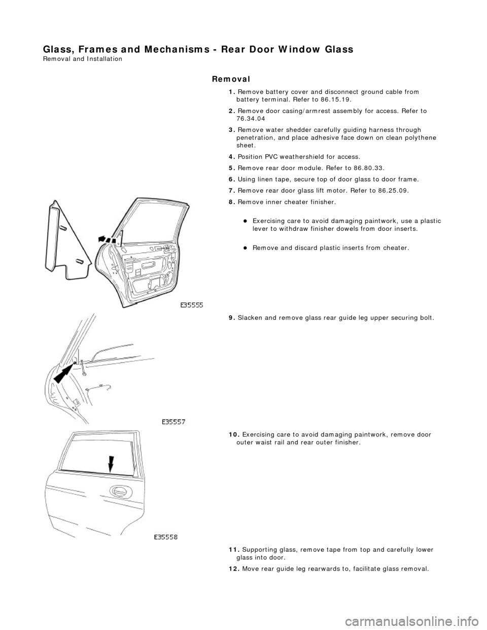
8. Remove inner cheater finisher.
Exercising care to avoid dama ging paintwork, use a plastic
lever to withdraw finisher dowels from door inserts.
Remove and discard plasti c inserts from cheater.
9. Slacken and remove glass rear guide leg upper securing bolt.
10. Exercising care to avoid damaging paintwork, remove door
outer waist rail and rear outer finisher.
11. Supporting glass, remove tape from top and carefully lower
glass into door.
12. Move rear guide leg rearwards to, facilitate glass removal.
Page 2194 of 2490
Glass, Frames and Mechanisms - Rear Door Window Glass Weatherstrip
Removal and Installation
Removal
Installation
1.
Pull seal out of door frame channelling and discard seal.
2. Clean channelling ensuring that any residual adhesive is
removed.
1. Avoiding adhesive at ends, apply a suitable dry lubricant to
seal.
2. Commencing at front of frame, feed seal into channelling
ensuring it is uniformly tensioned and free from kinks.
3. Wipe residual lubricant fro m adhesive contact areas.
4. Remove protective tape from en ds and press adhesive firmly
onto frame.
5. Clean any excess lubricant from external surfaces and check
that door shuts correctly.
Page 2195 of 2490
Glass, Frames and Mechanisms - Rear Door Window Regulator and Motor
Removal and Installation
Removal
1. Ensure that door glass is in fully up position.
2. Remove battery cover and disc onnect ground cable from
battery terminal. Refer to 86.15.19.
3. Remove casing/armrest asse mbly from door. Refer to
76.34.01.
4. Remove water shedder carefu lly guiding harness through
penetration, and place adhesive face down on clean polythene
sheet.
5. Position PVC inner weat hershield for access.
6. Remove rear door module. Refer to 86.80.34.
7. Using linen tape, secure to p of glass to door frame.
8. Disconnect harness mult iplug from lift motor.
9. Slacken and remove screws and nuts securing lift motor to
door.
10. Mark position of door glass gu ide securing screws and slacken and remove screws.
11. Separate motor/regulator assembly from glass, lower into
bottom of door and remove assembly from door.
Page 2196 of 2490

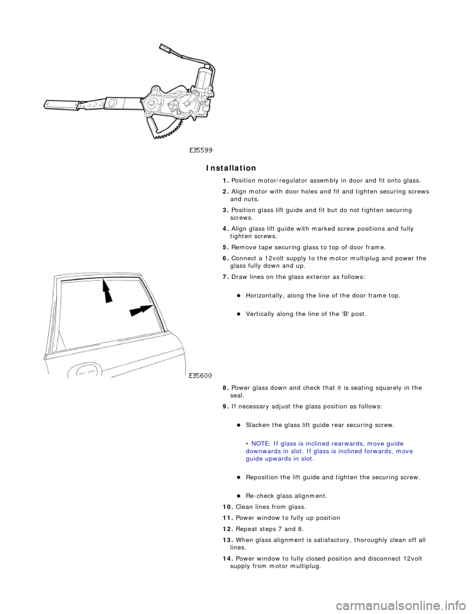
Installation
1. Position motor/regulator assembly in door and fit onto glass.
2. Align motor with door holes and fit and tighten securing screws
and nuts.
3. Position glass lift guide and fi t but do not tighten securing
screws.
4. Align glass lift guide with marked screw positions and fully
tighten screws.
5. Remove tape securing glass to top of door frame.
6. Connect a 12volt supply to the motor multiplug and power the
glass fully down and up.
7. Draw lines on the glass exterior as follows:
Horizontally, along the line of the door frame top.
Vertically along the line of the 'B' post.
8. Power glass down and check that it is seating squarely in the
seal.
9. If necessary adjust the glass position as follows:
Slacken the glass lift guid e rear securing screw.
• NOTE: If glass is inclin ed rearwards, move guide
downwards in slot. If glass is inclined forwards, move
guide upwards in slot.
Reposition the lift guide and tighten the securing screw.
Re-check glass alignment.
10. Clean lines from glass.
11. Power window to fully up position
12. Repeat steps 7 and 8.
13. When glass alignment is satisfac tory, thoroughly clean off all
lines.
14. Power window to fully closed po sition and disconnect 12volt
supply from motor multiplug.
Page 2198 of 2490
Glass, Frames and Mechanisms - Rear Door Window Regulator Motor
Removal and Installation
Removal
Installation
1.
Remove lift motor and regulator assembly from door. Refer to
86.25.09.
2. Slacken and remove th ree screws securing motor to regulator.
3. Remove lift motor from regulator.
1. Position lift motor on regulator and fit and tighten securing
screws.
2. Fit lift motor and regulator assembly in door. Refer to
86.25.09.
Page 2199 of 2490
Glass, Frames and Mechanisms - Rear Door Window Control Switch
Removal and Installation
Removal
Installation
1.
Remove casing/armrest asse mbly from door. Refer to
76.34.04.
2. Remove armrest from casing. Refer to 76.34.23.
3. Position armrest for access, slacken and remove two
switchpack securing screws and remove switchpack assembly from armrest.
4. Slacken and remove screws securing veneer panels to switch
and ashtray.
1. Position veneer panels on sw itch and ashtray, and fit and
tighten securing screws.
2. Position switch/ashtray assembly on armrest and fit and
tighten securing screws.
3. Fit armrest to door casing. Refer to 76.34.23.
4. Fit casing/armrest assembly to door. Refer to 76.34.04.
Page 2200 of 2490
Glass, Frames and Mechanisms - Rear Quarter Window Glass
Removal and Installation
Removal
Special Tool(s)
Spray Bottle
WK9
Lubricant Concentrate
WK9L
Power Cutting Tool
WK10HD
Cutting Blade - Side
WK4ZS
Adhesive Removal Blade - Body
WK6
Betagun pneumatic application gun
Betagun 111
1. Remove the rear seat backrest.
For additional information, refer to: Rear Seat Backrest
(501-
10 Seating, Removal and Installation).
2. Remove both C-pill ar trim panels.
For additional information, refer to: C
-Pillar Trim Panel (501-05
Interior Trim and Ornamentatio n, Removal and Installation).
3. Place a suitable protective sheet over the parcel shelf and place
a protecting boar d over sheet.
4. Dispense 20ml of WK9L lubricant into the WK9 spray bottle, fill