Page 1921 of 2490

License plate lamps
Each license plate bulb is accessible after removing the relevant lens. The license plate lamps can be accessed following
removal of the trunk lid liner and upper trim finisher.
Rear lamp assembly
Each rear lamp assembly incorporates a stop/tail lamp, a fog lamp, a reversing lamp and a direction indicator lamp. Access
for bulb replacement is from the trunk.
Side markers
Each side marker is retained in the bumper cover by a lug on one end of the unit and a spring clip at the other end. The unit is not electrically connected for all markets.
High mounted stop lamp
The high mounted stop lamp (HMSL) is secu red to studs on the center lower edge of the backlight and provides illumination
using five bulbs.
Operation
All lamps are controlled by the BPM which pr ovides an appropriate output in response to an input received when a selected
switch is operated.
The side marker lamps receive an input from the BPM via relay 3 and fuse F21. The license plate lamps receive an input
from the BPM via relay 3 and fuse F19. The rela y and fuses are located in the trunk fuse-box.
The tail lamps receive an input direct from the BPM.
The stop, reversing and rear fog lamps are controlled by the security and locking module (SLM) which receives inputs via
the SCP network from the BPM.
The HMSL is not controlled by the SLM; it receives input from the brake switch via relay 5 and fuse F8 in the trunk fuse-box.
The BPM and SLM monitor the stop lamps (n ot HMSL) and tail lamps for failure.
Fault analysis must be undertaken using the PDU, refer to Diagnosis and Testing.
Consult the relevant Electrical Guid e for details of circuit operation.
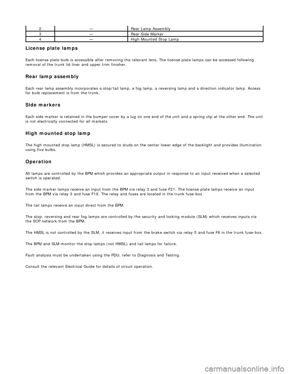
2—Rear Lamp Assembly
3—Rear Side Marker
4—High Mounted Stop Lamp
Page 1926 of 2490
Exterior Lighting - Front Fog Lamp
Removal and Installation
Removal
Installation
1.
Remove undertray for ac cess. Refer to 76.22.90.
2. Disconnect fog lamp harness multiplug.
3. Remove the three fog la mp securing bolts.
4. Withdraw fog lamp assembly from rear of bumper.
1. NOTE: Vertical alignment of the fog lamp is pre-set. No
attempt must be made to alter this setting.
Position fog lamp assembly on bumper.
2. Install fog lamp securing bolts.
3. Connect fog lamp harness multiplug.
4. Install undertray. Refer to 76.22.90.
Page 1928 of 2490
Exterior Lighting - Front Side Marker Lamp
Removal and Installation
Removal
Installation
1. Remove lamp unit.
Apply gentle thumb pressure to front end of lamp lens.
Exercising care to avoid damaging paintwork, compress
rear spring clip to release lamp unit.
Disconnect harness connector.
1. Position lamp at bumper an d connect harness connector.
2. Engage lamp front tang in bumper aperture.
3. Pivot lamp, compress rear clip and fully seat lamp in bumper.
Page 1929 of 2490
Exterior Lighting - Front Side Marker Lamp Bulb
Removal and Installation
Removal
1. Applying firm hand pressure to front end, pivot lamp assembly
for access to rear end.
2. Exercising care to avoid dama ging paintwork, use a small
screwdriver at rear end of lamp, to press and release retaining
tang.
3. Withdraw lamp from bumper for access and disconnect harness multiplug.
4. Rotate bulb holder 1/4 turn counter-clockwise to release it
from lamp assembly.
5. Withdraw bulb from holder.
Page 1930 of 2490
Installation
1. Install bulb in holder.
2. Install bulb and bulb holder in lamp assembly and rotate 1/4
turn clockwise to seat and retain.
3. Position direction lamp at bumper aperture and connect
harness multiplug.
4. Engage front end tang of lamp in bumper aperture.
5. Pivot lamp assembly and firmly seat rear retaining clip in
bumper aperture.
Page 1954 of 2490
Exterior Lighting - Rear Side Marker Lamp
Removal and Installation
Removal
Installation
1. Applying firm thumb pressure to front of lens, pivot lamp
assembly for access to rear end.
2. Exercising care to avoid dama ging paintwork, use a small
screwdriver to press and re lease rear retaining clip.
3. Withdraw lamp from bumper for access and disconnect harness connector.
1. Position lamp at bumper ap erture and connect harness
connector.
2. Engage front end tang of lamp in bumper aperture.
3. Pivot lamp assembly and firmly seat rear retaining clip in
bumper aperture.
Page 1955 of 2490
Exterior Lighting - Rear Side Marker Lamp Bulb
Removal and Installation
Removal
1. Applying firm thumb pressure to front of lens, pivot lamp
assembly for access to rear end.
2. Exercising care to avoid dama ging paintwork, use a small
screwdriver to press and re lease rear retaining clip.
3. Withdraw lamp from bumper for access and disconnect harness connector.
4. Rotate bulb holder 1/4 turn counter-clockwise to release it
from lamp assembly.
5. Withdraw bulb from holder.
Page 1956 of 2490
Installation
1. Install bulb in holder.
2. Install bulb and bulb holder in lamp assembly and rotate 1/4
turn clockwise to seat and retain.
3. Position lamp at bumper ap erture and connect harness
connector.
4. Engage front end tang in bumper aperture.
5. Pivot lamp assembly and firmly seat rear retaining clip in
bumper aperture.