Page 316 of 2490

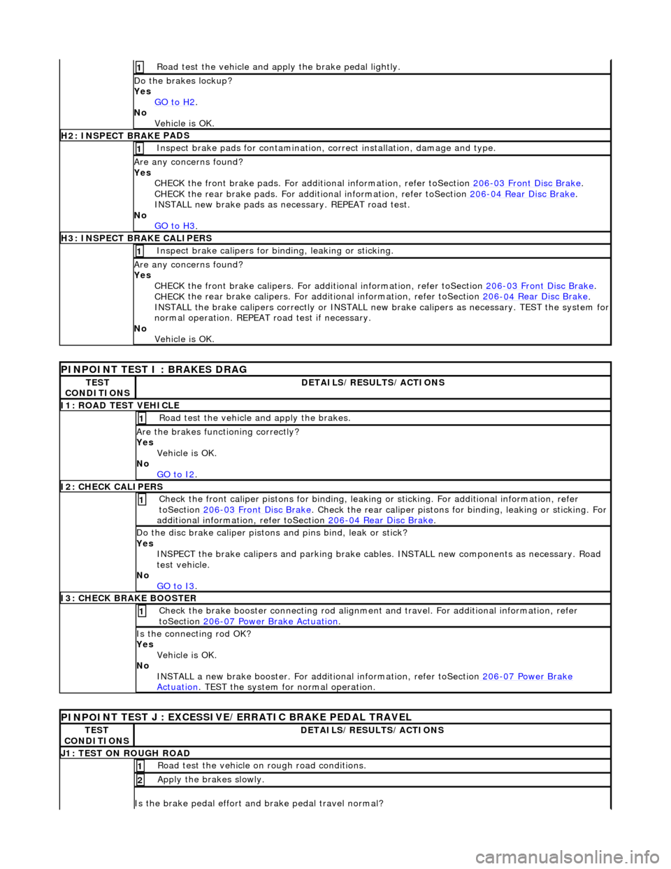
Road test the veh
icle and a
pply the brake pe dal lightly.
1
Do th
e brakes lockup?
Yes GO to H2
.
No
Vehicle is OK.
H2: INSPECT BRAKE PADS
Inspect brake pads for con
t
amination,
correct installation , damage and type.
1
Ar
e any concerns found?
Yes CHECK the front brake pads. For additi onal information, refer toSection 206
-03 Fr
ont Disc Brake
.
CHECK
the rear brake pads. For additi
onal information, refer toSection 206
-04
Rear Disc Brake
.
INST ALL new brake pads as ne ce
ssary. REPEAT
road test.
No GO to H3
.
H3: INSPECT BRAKE CALI
PERS
Inspect brake cali
pers for bindi
ng, leaking or sticking.
1
A
r
e any concerns found?
Yes CHECK the front brake calipers. For addi tional information, refer toSection 206
-03 Fr
ont Disc Brake
.
CHECK
the rear brake calipers. For addi
tional information, refer toSection 206
-04
Rear Disc Brake
.
IN ST
ALL the brake calipers correctly or INSTALL new
brake calipers as necessary. TEST the system for
normal operation. REPEAT road test if necessary.
No Vehicle is OK.
PI
NPOINT TEST I : BRAKES DRAG
TE
S
T
CONDITIONS
D E
TAILS/RESULTS/ACTIONS
I1
:
ROAD TEST VEHICLE
Ro
ad t
est the vehicle
and apply the brakes.
1
Are the brakes
functioning correctly?
Yes Vehicle is OK.
No GO to I2
.
I2
: CHECK CALIPERS
Check the fr
on
t caliper pistons for binding, leakin
g or sticking. For additional information, refer
toSection 206
-03 Fr
ont Disc Brake
. Check the rear cal
i
per pistons for
binding, leaking or sticking. For
additional information, refer toSection 206
-04
Rear Disc Brake
.
1
Do t
h
e disc brake caliper pistons
and pins bind, leak or stick?
Yes INSPECT the brake calipers and pa rking brake cables. INSTALL new co mponents as necessary. Road
test vehicle.
No GO to I3
.
I3
: CHECK BRAKE BOOSTER
Check the brake booster con
n
ecting rod alignment
and travel. For additional information, refer
toSection 206
-0 7
Power Brake Actuation
. 1
Is the co
nnecti
ng rod OK?
Yes Vehicle is OK.
No INSTALL a new brake booster. For addi tional information, refer toSection 206
-07
Power Brake
Actuation. TEST
the system for
normal operation.
PINPO
I
NT TEST J : EXCESSIVE/ERRATIC BRAKE PEDAL TRAVEL
TE
S
T
CONDITIONS
D E
TAILS/RESULTS/ACTIONS
J
1
: TEST ON ROUGH ROAD
R
oad test the vehi
cle on rough road conditions.
1
Apply the brakes slowly. 2
Is th
e brake pedal ef
fort an
d brake pedal travel normal?
Page 321 of 2490
Front caliper bleed
nipple: 4-6
Nm.
Rear caliper
bleed
nipple: 8-11 Nm.
7. F
ollowing the procedure below,
bleed the brakes in the order
shown:
1. Left-Hand Front,
2. Right-Hand Front,
3. Left- Hand Rear,
4. Right-Hand Rear.
8. CAUTI
ON: Remove brake flui
d spillage immediately from
paint work with clean water.
Fill fluid reservoir.
F
ill reservoir to the 'MAX' mark.
F
it filler cap.
9.
Start e
ngine.
10. Check for correct brake-pedal travel and pressure.
11. Apply brake pedal and check around vehicle for brake fluid
leaks.
12. Make sure brake fluid level is at the 'MAX' mark.
Page 323 of 2490
4
. Close bleed nipple.
5. Release brake pedal.
6. Wait two seconds to allow system to prime.
7. Repeat procedure until air- free brake fluid is expelled
from the bleed nipple.
8. Repeat procedure to ca liper's inner bleed nipple.
6. Tigh
ten bleed nipples to 12-16 Nm.
7. F
ollowing the procedure above,
bleed the brakes in the order
shown:
1. Left-Hand Front,
2. Right-Hand Front,
3. Left- Hand Rear,
4. Right-Hand Rear.
8. CAUTI
ON: Remove brake flui
d spillage immediately from
paint work with clean water.
Fill fluid reservoir.
F
ill reservoir to the 'MAX' mark.
F
it filler cap.
9.
Start e
ngine.
10. Check for correct brake-pedal travel and pressure.
11. Apply brake pedal and check around vehicle for brake fluid
leaks.
12. Make sure brake fluid level is at the 'MAX' mark.
Page 331 of 2490
R
ear Brake Disc Runout Check Vehicles Without: Brembo Brakes
Special Service tools
D
ial Test Indicator Gauge and Stand.
1
. Raise rear of vehicle and support on stands. Refer to section
<<100-02>>.
2. Remove wheel.
3
.
C
AUTION:
Tie caliper housing aside. Do not allow the caliper housing to hang on the hydraulic hose, as this
will damage the hose.
Remove caliper housing from caliper carrier. 1. Remove anti-rattle spring.
2. Remove dust covers.
3. Remove guide pins.
4. Remove housing from carrier.
Tie caliper housing aside.
4. NOTE:
Page 334 of 2490
Rear
Brake Disc Runout Check Vehicles With: Brembo Brakes
Special Service tools
Di
al Test Indicator Gauge and Stand.
1.
WA
RNING:
BRAKE DUST, IF INHALED CAN DAMAGE YOUR HEALTH. ALWAYS REMOVE BRAKE DUST USING A VACUUM BRUSH. DO NOT USE A COMPRESSED-AIR LINE TO DISPERSE BRAKE DUST
INTO THE ATMOSPHERE.
CA
UTION:
Replacement of nuts and bolts: Various thread-locking devices are used on nuts and bolts
throughout the vehicle. These devices restrict the number of times a nut or bolt can be used. See
section <<100-00>> for information.
CA
UTION:
The Brembo caliper is aligned to the brake disc when it is first installed to the vehicle, therefore,
care must be taken not to disturb this alignment. When removing the caliper; remove the bolts
that secure the anchor bracket to the hub carrier only. DO NOT loosen any other caliper bolts.
Raise rear of vehicle and support on stands. Refer to section <<100-02>>.
2. Remove wheel. Refer to operation <<74.20.05>>.
Page 339 of 2490

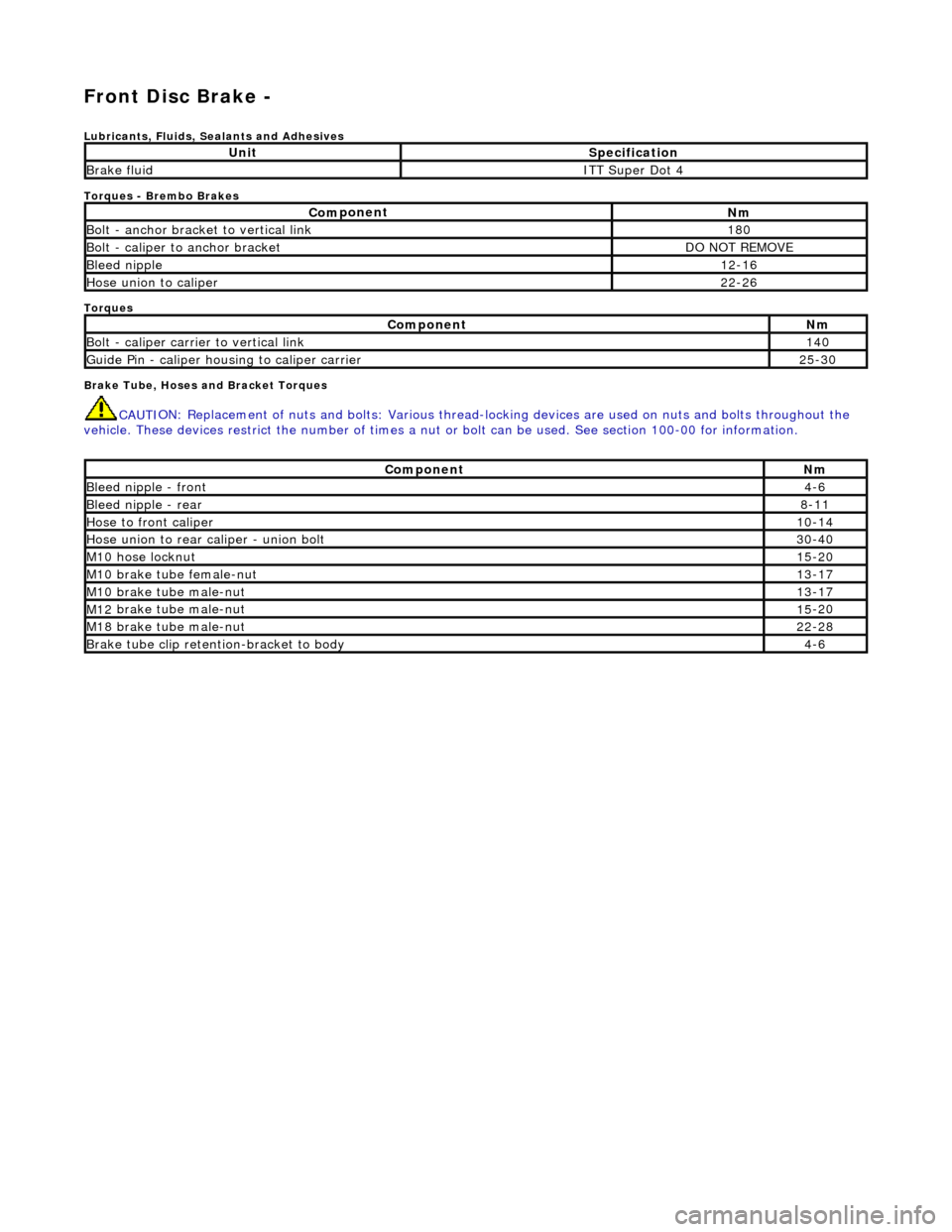
Front Disc Brake -
Lubri
cants, Fluids, Sealants and Adhesives
Torques - Brembo Brakes
Torques
Brake Tube, Hoses and Bracket Torques
CAUTI
ON: Replacement of
nuts and bolts: Various thread-locking devices are used on nuts and bolts throughout the
vehicle. These devices restrict the number of times a nut or bolt can be used. See section 100-00 for information.
UnitS
pecification
Brake flu
id
ITT Supe
r Dot 4
Com
ponent
Nm
B
olt - anchor bracket to vertical link
18
0
Bo
lt - caliper to anchor bracket
DO
NOT REMOVE
Bleed n
ipple
12
-16
Hose u
nion to caliper
22
-26
Com
ponent
Nm
Bol
t - caliper carrier to vertical link
14
0
Guide
Pin - caliper housing to caliper carrier
25
-30
Com
ponent
Nm
Bleed n
ipple - front
4-
6
Bleed n
ipple - rear
8-1
1
Hose to fr
ont caliper
10
-14
Hose union to rear cal
iper - union bolt
30
-40
M1
0 hose locknut
15
-20
M10
brake tube female-nut
13
-17
M10
brake tube male-nut
13
-17
M12
brake tube male-nut
15
-20
M18
brake tube male-nut
22
-28
Brake tube clip retention
-bracket to body
4-
6
Page 343 of 2490

Front Disc Brake - Brake CaliperVehicles
With: Standard Brakes
Re
moval and Installation
Remov
al
W
ARNING: BRAKE DUST, IF INHALED CAN DAMAGE YOUR
HEALTH. ALWAYS REMOVE BRAKE DUST USING A VACUUM
BRUSH. DO NOT USE A COMPRESSED-AIR LINE TO DISPERSE BRAKE DUST INTO THE ATMOSPHERE.
• CAUTIONS:
Replacement of nuts and bolts: Various thread-locking de vices are used on nuts and bolts throughout the vehicle.
These devices restrict the number of times a nut or bolt can be used. See section 100-00 for information.
Remove brake fluid spilla ge immediately from paint work, with clean water.
A new brake hose must be installe d when replacing a brake caliper.
The brake pad adhesive backing must not be reused, therefore always install new brake pads, irrespective of the
condition of the original pads when replacing a brake caliper. Always replace brake pads as an axle set.
S
pecial Tool(s)
Brake Pedal
Hold Tool
JDS 9013
1. O
pen engine compartment and fit
paint work protection covers
to fenders.
2. Raise vehicle on a four-post lift.
3. Raise front of vehicle and support on stands. Refer to Section
100-02.
4. Remove front wheels. See Section 204-04.
5. NOTE
: The following three pictorial procedures must be
carried-out to minimize brake fl uid loss when disconnecting the
brake hose.
Open Left-Hand-Front and Left-H and-Rear caliper bleed nipples.
Connect
a bleed tube and co
ntainer to the calipers.
O
pen bleed nipples.
6. Depress and hold down brak e pedal at the specified
measurement using special tool.
1. Position tool between brake pedal and seat frame.
2. Turn the tool wheel unti l the brake pedal is held
Page 347 of 2490

Front Disc Brake - Brake CaliperVehicles With: High Performance Brakes
Re
moval and Installation
Remov
al
S
pecial Tool(s)
Brake Pedal
Hold Tool
JDS 9013
1. WARNING: BRAKE DUST, IF INHALED CAN DAMAGE
YOUR HEALTH. ALWAYS REMOVE BRAKE DUST USING A VACUUM
BRUSH. DO NOT USE A COMPRE SSED-AIR LINE TO DISPERSE
BRAKE DUST INTO THE ATMOSPHERE.
• CAUTIONS:
Replacement of nuts and bolts: Various thread-locking
devices are used on nuts and bolts throughout the vehicle. These
devices restrict the number of ti mes a nut or bolt can be used.
See section 100-00 for information.
Remove brake fluid spillage immediately from paint work,
with clean water.
The Brembo caliper is aligned to the brake disc when it is
first installed to the vehicle, therefore, care must be taken not to
disturb this alignment. When removing the caliper; remove the
bolts that secure the anchor bracket to the vertical link only. DO
NOT loosen any other caliper bolts.
Open engine compartment and fit paint work protection covers
to fenders.
2. R
aise vehicle on a four-post lift.
3. Raise front of vehicle and support on stands. Refer to Section
100-02.
4. Remove front wheels. Refe r to operation 74.20.05.
5. NOTE
: The following three pictorial procedures must be
carried-out to minimize brake fl uid loss when disconnecting the
brake hose.
Open Left-Hand-Front and Left-H and-Rear caliper bleed nipples.
Connect
a bleed tube and co
ntainer to the calipers.
O
pen bleed nipples.
6. Depress and hold down brak e pedal at the specified
measurement using the special tool.