Page 461 of 2490

sus
pension components
and for damaged coil springs in the front suspension.
as necessary. For addi tional information,
REF
ER to Section 204
-0
2 Rear Suspension
. I
NSTALL new front suspension components
as necessary. For addi tional information,
REFER to Section 204
-01
Front Suspension
.
Chec
k the rear suspension
for loose or worn
suspension components.
TIGHTE
N or INSTALL new components as
necessary. For additi onal information,
REFER to Section 204
-0
2 Rear Suspension
.
Incorre
ct underbody
alignment.
CHECK
underbody alignment. For additional
information,
REFER to Section 502
-00
Uni
-Body, Subframe and M
ounting System
.
Poor r
eturnability of the
steering
Lower steeri
ng column
interference.
CHECK
the steering co
lumn is free from
interference from the en gine harness, sound
proofing or the floor covering.
Incorrect
tire pressure.
CHECK
and ADJUST the tire pressure. For
additional information,
REFER to Section 204
-0
4 Wheels and Tires
.
Incorrect
tire size or type.
IN
STALL a new tire as necessary. For
additional information,
REFER to Section 204
-0
4 Wheels and Tires
.
Steeri
ng column upper
shroud fouling on the steering wheel.
CHECK
steering column upper shroud for
fouling. ADJUST as necessary.
Steeri
ng column universal
joints binding.
IN
STALL a new steering column. For
additional information,
REFER to Section 211
-0
4 Steering Column
.
Steeri
ng column shaft floor
seal binding.
CHE
CK the steering column shaft floor seal
for correct fitm ent and REFIT as necessary.
Steeri
ng column shaft floor
seal may be torn.
IN
STALL a new steering column shaft floor
seal as necessary.
Bin
ding or damaged tie-
rods.
CHECK
tie-rod end for excessive wear or
tightness in ball joint. INSTALL a new tie- rod end. For additional information,
REFER to Section 211
-0
3 Steering Linkage
.
D
amaged or worn front
suspension components.
I
NSTALL new front suspension components
as necessary. For addi tional information,
REFER to Section 204
-01
Front Suspension
.
Incorre
ct toe adjustment.
AD
JUST as necessary. For additional
information,
REFER to Section 204
-00
Suspension
Sy
stem
- General
Information
.
Excessive steeri
ng efforts
required during low speed
manoeuvring and/or during parking manoeuvres
Low power steer
ing fluid.
CHE
CK steering system
for signs of steering
fluid loss.
BLEE
D the power steering system. For
additional information,
REFER to Section 211
-0
0 Steering System
- General Informati
on
.
Damaged accessory driv
e
belt tensioner.
INST
ALL a new accessory drive belt
tensioner.
Hose or cooler li
ne
restriction.
CHECK
hose or cooler lines for correct
routing.
INST
ALL a new hose as necessary.
Fl
uid aeration.
BLEE
D the system. For additional
information,
REFER to Power Steering System Bleeding
in t
his section.
Steeri
ng transducer not
closed - no feed voltage.
CHECK
the steering transducer circuit. For
additional information, REFER to the wiring diagrams.
Carry ou
t the electrical checks and tests.
For additional information, REFER to the
Electrical Checks and Tests in this section.
Steeri
ng transducer not
closed - cable fault.
CHECK
the steering transducer circuit. For
additional information, REFER to the wiring diagrams.
Carry ou
t the electrical checks and tests.
Page 531 of 2490

En
gine - Engine
D
iagnosis and Testing
Sym
ptom Chart
Sy
mptom Chart
Pinp
oint test A: P1392 (P1397)
VVT solenoid circuit low input
S
pecial Tool(s)
D
igital multimeter
Generi
c scan tool
Sy
mptom
Possib
le Sources
Acti
on
D
TC P1392 VVT solenoid A circuit low input
So
lenoid coil open circuit
Harness open circuit or blown fuse
Connector pins(s) bent , loose or corroded
*
*
*
GO to
P
inpoint Test A
*
D
TC P1397 VVT solenoid B circuit low input
So
lenoid coil open circuit
Harness open circuit or blown fuse
Connector pins(s) bent , loose or corroded
*
*
*
GO to
P
inpoint Test A
*
D
TC P1393 VVT solenoid A circuit high input
So
lenoid coil short circuit
Harness short circuit
Connector pins(s) bent , loose or corroded
*
*
*
GO to
P
inpoint Test B
*
D
TC P1398 VVT solenoid B circuit high input
So
lenoid coil short circuit
Harness short circuit
Connector pins(s) bent , loose or corroded
*
*
*
GO to
P
inpoint Test B
*
D
TC P1396 VVT solenoid B malfunction
O
il pressure failure
VVT solenoid sticking
Connector pins(s) bent , loose or corroded
Crankshaft position sensor failure
ECM failure
*
*
*
*
*
GO to
P
inpoint Test C
*
P
INPOINT TEST A : P1392 (P1397) VVT SOLENOID CIRCUIT LOW INPUT
•
NOTE: References in brac
kets are for Bank B (2)
T
EST CONDITIONS
D
ETAILS/RESULTS/ACTIONS
A1
: RETRIEVE DTCS
•
NOTE: Battery and or ECM disconnection prior to scanning wi
ll erase all data, ensure that the correct DTC is present.
Page 575 of 2490

2
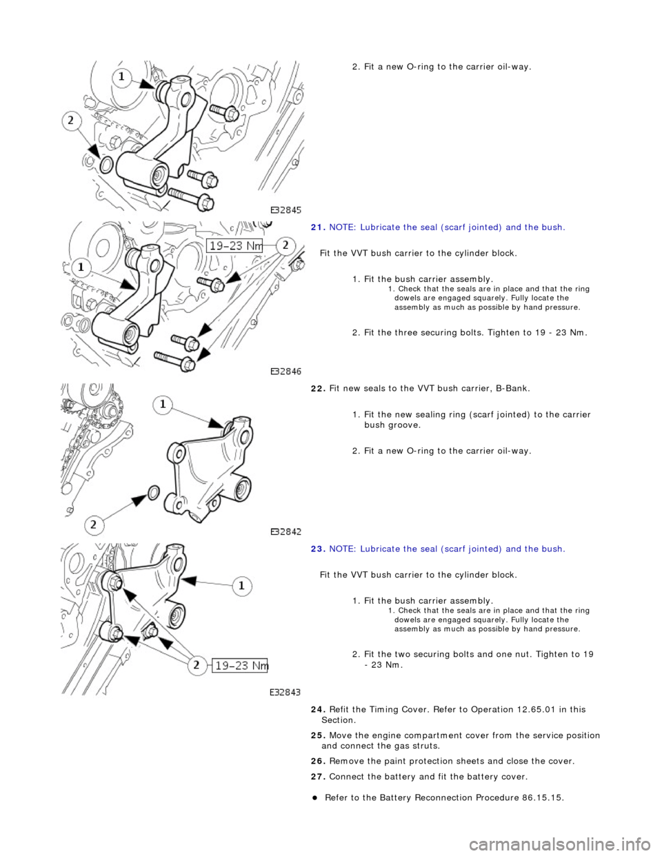
. Fit a new O-ring to the carrier oil-way.
21
.
NOTE: Lubricate the seal (s carf jointed) and the bush.
Fit the VVT bush carrier to the cylinder block.
1. Fit the bush carrier assembly.
1. C
heck that the seals are in place and that the ring
dowels are engaged squa rely. Fully locate the
assembly as much as possible by hand pressure.
2
. Fit the three securing bolts. Tighten to 19 - 23 Nm.
22
.
Fit new seals to the VVT bush carrier, B-Bank.
1. Fit the new sealing ring (scarf jointed) to the carrier bush groove.
2. Fit a new O-ring to the carrier oil-way.
23
.
NOTE: Lubricate the seal (s carf jointed) and the bush.
Fit the VVT bush carrier to the cylinder block. 1. Fit the bush carrier assembly.
1. C
heck that the seals are in place and that the ring
dowels are engaged squa rely. Fully locate the
assembly as much as possible by hand pressure.
2
. Fit the two securing bolts and one nut. Tighten to 19
- 23 Nm.
24. Refit the Timing Cover. Refer to Operation 12.65.01 in this
Section.
25. Move the engine compartment cover from the service position
and connect the gas struts.
26. Remove the paint protection sheets and close the cover.
27. Connect the battery and fit the battery cover.
Re
fer to the Battery Reconnection Procedure 86.15.15.
Page 592 of 2490
2.
Fit a new O-ring to the carrier oil-way.
14. F
it the VVT bush carrier to the cylinder block.
Lubric
ate the seal (scarf
jointed) and the bush.
1. Fit the bush carrier assembly.
Check that th e seals are in pl ace an
d that the ring dowels
are engaged squarely. Fully locate the assembly as much
as possible by hand pressure.
2. Fit the three securing bolts. Tighten to 19-23 Nm.
15. Refit the Timing Cover. Refer to Operation 12.65.01 in this
Section.
16. Move the engine compartment cover from the service position
and connect the gas struts.
17. Remove the paint protection sheets and close the cover.
18. Connect the battery and fit the battery cover.
Refe
r to the Battery Reconnection Procedure in Section
414-01.
Page 625 of 2490

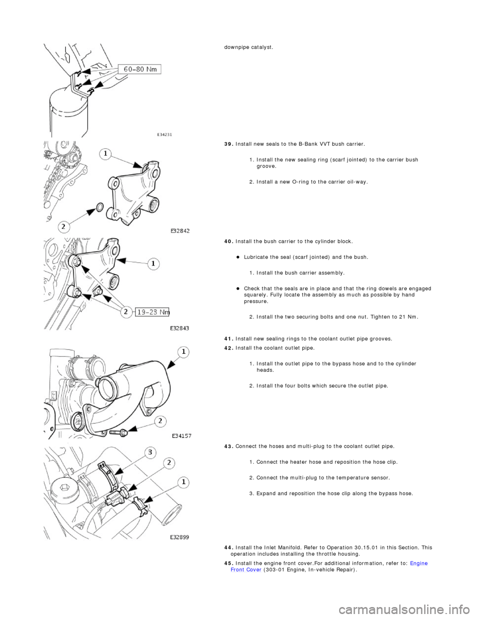
d
ownpipe catalyst.
39
.
Install new seals to the B-Bank VVT bush carrier.
1. Install the new sealing ring (scarf jointed) to the carrier bush groove.
2. Install a new O-ring to the carrier oil-way.
40
.
Install the bush carrier to the cylinder block.
Lu
bricate the seal (scarf
jointed) and the bush.
1. Install the bush carrier assembly.
Chec
k that the seals are
in place and that the ri ng dowels are engaged
squarely. Fully locate the assembly as much as possible by hand
pressure.
2. Install the two securing bolts and one nut. Tighten to 21 Nm.
41. Install new sealing rings to the coolant outlet pipe grooves.
42
.
Install the coolant outlet pipe.
1. Install the outlet pipe to the bypass hose and to the cylinder heads.
2. Install the four bolts which secure the outlet pipe.
43
.
Connect the hoses and multi-plug to the coolant outlet pipe.
1. Connect the heater hose and reposition the hose clip.
2. Connect the multi-plug to the temperature sensor.
3. Expand and reposition the hose clip along the bypass hose.
44. Install the Inlet Manifold. Refer to Operation 30.15.01 in this Section. This
operation includes installing the throttle housing.
45. Install the engine front cover.For additional information, refer to: Engine
Front Cover (303-01 Engi
ne, In-vehicle Repair).
Page 640 of 2490

2. In
stall the access grommet to the housing.
36. Lower the ramp.
37. Ins
tall and tighten the nuts which secure the exhaust manifold to the
downpipe catalyst.
38 . In
stall new seals to the A-Bank VVT bush carrier.
1. Install the new sealing ring (scarf jointed) to the carrier bush groove.
2. Install a new O-ring to the carrier oil-way.
39 . Install the bush c
arrier to the cylinder block.
Lu
br
icate the seal (scarf
jointed) and the bush.
1. Install the bush carrier assembly.
Chec k that
the seals are
in place and that the ri ng dowels are engaged
squarely. Fully locate the assembly as much as possible by hand
pressure.
2. Install the three securing bolts. Tighten to 21 Nm.
40. Install new sealing rings to the coolant outlet pipe grooves.
41. Install the coolant
outlet pipe.
1. Install the outlet pipe to the bypass hose and to the cylinder heads.
2. Install the four bolts which secure the outlet pipe.
42. Connect the hoses and multi-plug to the coolant outlet pipe.
1. Connect the heater hose and reposition the hose clip.
Page 754 of 2490
Engine - Oil Pressure Switch
In-vehicle Repair
Removal
Installation
1.
Raise vehicle on four post ramp.
2. Remove oil pressure switch.
Disconnect connector.
Remove oil pressure switch from oil filter head.
1. NOTE: Fit new sealing washer to oil pressure switch.
Installation is reverse of removal.
Page 768 of 2490
14. Remove the camshaft locking tool 303 - 530.
15. Raise the vehicle on the ramp.
16. Remove the crankshaft setting tool 303 - 531.
17. Refit the crankshaft position sensor.
1. Fit the sensor to the fl ywheel housing and fit the
securing bolt. Tighten to 8 - 12 Nm.
2. Refit the access grommet to the housing.
18. Lower the ramp.
19. Fit new seals to the VVT bush carrier, A-Bank.
1. Fit the new sealing ring ( scarf jointed) to the carrier
bush groove.
2. Fit a new O-ring to the carrier oil-way.
20. NOTE: Lubricate the seal (s carf jointed) and the bush.
Fit the VVT bush carrier to the cylinder block.
1. Fit the bush carrier assembly.
1. Check that the seals are in place and that the ring dowels are engaged squa rely. Fully locate the
assembly as much as possible by hand pressure.
2. Fit the three securing bolts. Tighten to 19 - 23 Nm.
21. Fit new seals to the VVT bush carrier, B-Bank.