1998 JAGUAR X308 oil pressure
[x] Cancel search: oil pressurePage 1760 of 2490
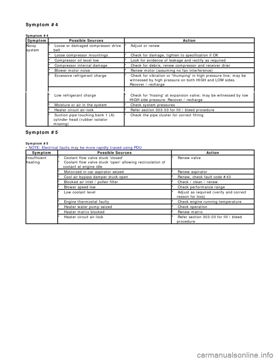
Symp
tom #5
Sy
m
ptom #5
Low r
e
frigerant charge
*
Check f or 'hissi
ng' at expansion
valve; may be witnessed by low
HIGH side pressure. Recover / recharge
*
Moi
s
ture or air in the system
*
Chec k syst
em pressures
*
Heat er ci
rcuit air-lock
*
R e
fer section 303-03 for fill / bleed procedure
*
Suct ion
pipe touching bank 1 (A)
cylinder head (rubber isolator
missing)
*
Check the pi
pe cluster for correct fitti
ng
*
• NOTE: Electrical faults may be more rapidly traced using PDU
Sym
ptom
Possib
l
e Sources
Acti
o
n
Insuffi
ci
ent
heating
Coo l
ant flow valve stuck 'closed'
Coolant flow valve stuck 'open' allowing recirculation of
coolant at engine idle
*
*
Re
new v
alve
*
Motorized in-car aspirator sei zed
*R e
new aspirator
*
Coo l
air bypass damper stuck open
*
Re new,
check fault code #43
*
B l
ocked air inlet / pollen filter
*
Chec k / cl
ean / renew
*
B l
ower speed low
*
Check performance range
*
Low cool ant
level
*
Adjust as req u
ired (verify and correct
reason for loss)
*
Engine
t
hermostat faulty
*
Check engine r u
nning temperature
*
Heater water pump seized
*Chec k op
eration
*
Heater ma trix
blocked
*
Re new m
atrix
*
Heater circui t
air-lock
*
R e
fer section 303-03 for fill / bleed
procedure
*
Sym
p
tom #4
Sym
ptom #4
Sy
m
ptom
Possib
l
e Sources
Acti
o
n
No
i
sy
system
Loose or damaged compressor drive
belt
*Adjust or r
e
new
*
Loose compressor mountings
*Check f o
r damage, tighten to specification if OK
*
Compressor oil level l
ow
*
Look for evidence of l
eakag
e and rectify as required
*
Compressor internal dama ge
*Check f o
r debris, renew compressor and receiver drier
*
B l
ower motor noise
*
Re new m
otor (assuming no fan interference)
*
Excessive refrige rant charge
*Check f o
r vibration or 'thumping'
in high pressure line; may be
witnessed by high pressure on both HIGH and LOW sides.
Recover / recharge
*
Page 1761 of 2490
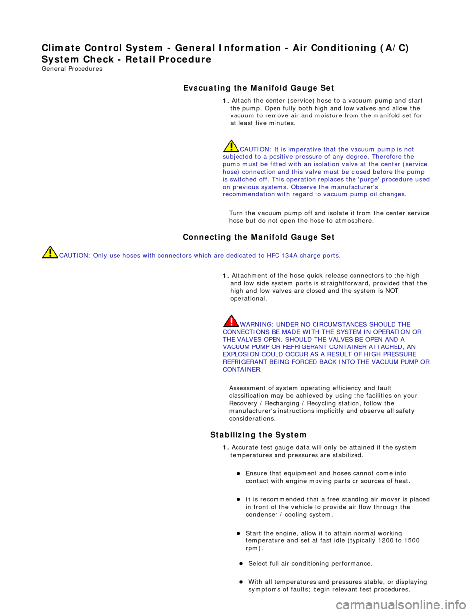
Climate Co
ntrol System - General In
formation - Air Conditioning (A/C)
System Check - Re tail Procedure
Gen
eral Procedures
E
vacuating the Manifold Gauge Set
Connecting the Manifold Gauge Set
C
AUTION: Only use hoses with connectors wh
ich are dedicated to HFC 134A charge ports.
Stabilizing the System
1.
At
tach the center (service) hose to a vacuum pump and start
the pump. Open fully both high and low valves and allow the
vacuum to remove air and mois ture from the manifold set for
at least five minutes.
CAUTION: It is imperative th at the vacuum pump is not
subjected to a positi ve pressure of any degree. Therefore the
pump must be fitted wi th an isolation valve at the center (service
hose) connection and this valve mu st be closed before the pump
is switched off. This operation replaces the 'purge' procedure used
on previous systems. Observe the manufacturer's
recommendation with regard to vacuum pump oil changes.
Turn the vacuum pump off and isol ate it from the center service
hose but do not open the hose to atmosphere.
1. Att
achment of the hose quick release connectors to the high
and low side system ports is stra ightforward, provided that the
high and low valves are closed and the system is NOT
operational.
WARNING: UNDER NO CIRCUMSTANCES SHOULD THE
CONNECTIONS BE MADE WITH THE SYSTEM IN OPERATION OR
THE VALVES OPEN. SHOULD THE VALVES BE OPEN AND A
VACUUM PUMP OR REFRIGERANT CONTAINER ATTACHED, AN
EXPLOSION COULD OCCUR AS A RESULT OF HIGH PRESSURE
REFRIGERANT BEING FORCED BACK INTO THE VACUUM PUMP OR
CONTAINER.
Assessment of system operating efficiency and fault
classification may be achieved by using the facilities on your
Recovery / Recharging / Recycling station, follow the
manufacturer's instructions implicitly and observe all safety
considerations.
1. Accurate test gauge data wi
ll on
ly be attained if the system
temperatures and pressures are stabilized.
E
nsure that equipment and hoses cannot come into
contact with engine moving parts or sources of heat.
It is recommended th at a free standing air
mover is placed
in front of the vehicle to provide air flow through the
condenser / cooling system.
St
art the engine, allow it to attain normal working
temperature and set at fast idle (typically 1200 to 1500
rpm).
Select full
air condit
ioning performance.
With
all temperatures and pres
sures stable, or displaying
symptoms of faults; begin relevant test procedures.
Page 1818 of 2490
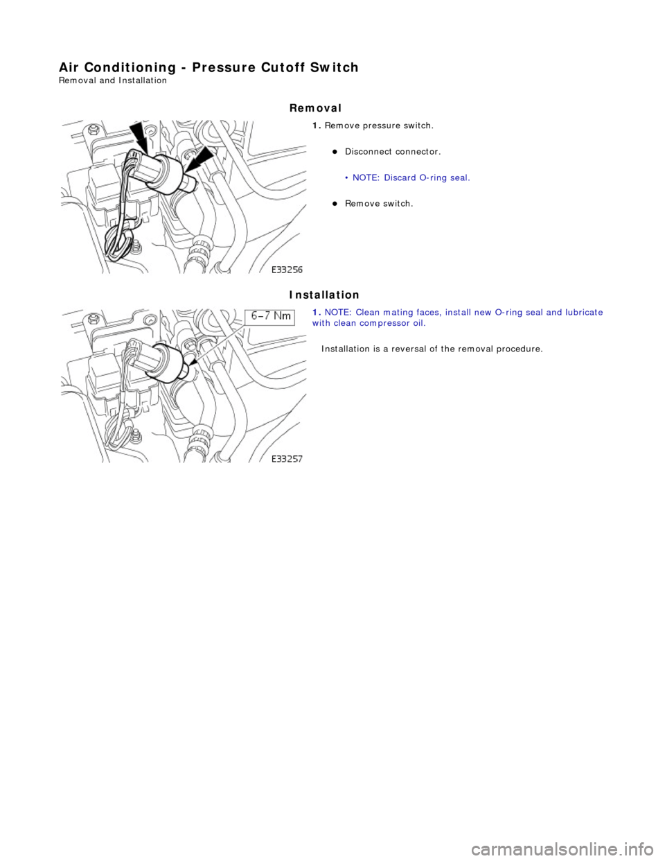
Air Conditioning - Pressure Cutoff Switch
Removal and Installation
Removal
Installation
1. Remove pressure switch.
Disconnect connector.
• NOTE: Discard O-ring seal.
Remove switch.
1. NOTE: Clean mating faces, instal l new O-ring seal and lubricate with clean compressor oil.
Installation is a reversal of the removal procedure.
Page 1837 of 2490
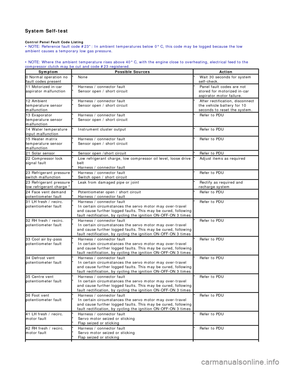
System Self-test
Control Panel Fault Code Listing • NOTE: Reference fault code #23*: In ambient temperatures below 0° C, this code may be logged because the low
ambient causes a tempor ary low gas pressure.
• NOTE: Where the ambient temperature rises above 40° C, with the engine close to overheating, electrical feed to the
compressor clutch may be cut and code #23 registered.
SymptomPossible SourcesAction
0 Normal operation no
fault codes presentNone
*Wait 30 seconds for system
self-check.
*
11 Motorized in-car
aspirator malfunctionHarness / connector fault
Sensor open / short circuit
*
*Panel fault codes are not
stored for motorized in-car
aspirator motor failure.
*
12 Ambient
temperature sensor
malfunctionHarness / connector fault
Sensor open / short circuit
*
*After rectification, disconnect
the vehicle battery for 10
seconds to reset the system.
*
13 Evaporator
temperature sensor
malfunctionHarness / connector fault
Sensor open / short circuit
*
*Refer to PDU
*
14 Water temperature
input malfunctionInstrument cl uster output
*Refer to PDU
*
15 Heater matrix
temperature sensor
malfunctionHarness / connector fault
Sensor open / short circuit
*
*Refer to PDU
*
21 Solar sensorSensor open /short circuit
*Refer to PDU
*
22 Compressor lock
signal faultLow refrigerant charge, low compressor oil level, loose drive
belt Harness / connector fault
*
*Adjust items as required
*
23 Refrigerant pressure
switch malfunctionHarness / connector fault
Switch open / short circuit
*
*Refer to PDU
*
23 Refrigerant pressure
low refrigerant charge * Leak from damaged pipe or joint
*Rectify as required and
recharge system
*
24 Face vent demand
potentiometer faultPotentiometer open / short circuit
Harness / connector fault
*
*Refer to PDU
*
31 LH fresh / recirc.
potentiometer faultHarness / connector fault
In certain circumstances the servo motor may over-travel
and cause further logged faults. This may be cured, following
fault rectification, by cycling the ignition ON-OFF-ON 3 times
*
*Refer to PDU
*
32 RH fresh / recirc.
potentiometer faultHarness / connector fault
In certain circumstances the servo motor may over-travel
and cause further logged faults. This may be cured, following
fault rectification, by cycling the ignition ON-OFF-ON 3 times
*
*Refer to PDU
*
33 Cool air by-pass
potentiometer faultHarness / connector fault
In certain circumstances the servo motor may over-travel
and cause further logged faults. This may be cured, following
fault rectification, by cycling the ignition ON-OFF-ON 3 times
*
*Refer to PDU
*
34 Defrost vent
potentiometer faultHarness / connector fault
In certain circumstances the servo motor may over-travel
and cause further logged faults. This may be cured, following
fault rectification, by cycling the ignition ON-OFF-ON 3 times
*
*Refer to PDU
*
35 Centre vent
potentiometer faultHarness / connector fault
In certain circumstances the servo motor may over-travel
and cause further logged faults. This may be cured, following
fault rectification, by cycling the ignition ON-OFF-ON 3 times
*
*Refer to PDU
*
36 Foot vent
potentiometer faultHarness / connector fault
In certain circumstances the servo motor may over-travel
and cause further logged faults. This may be cured, following
fault rectification, by cycling the ignition ON-OFF-ON 3 times
*
*Refer to PDU
*
41 LH fresh / recirc.
motor faultHarness / connector fault
Servo motor seized or sticking
Flap seized or sticking
*
*
*Refer to PDU
*
42 RH fresh / recirc.
motor faultHarness / connector fault
Servo motor seized or sticking
Flap seized or sticking
*
*
*Refer to PDU
*
Page 1854 of 2490
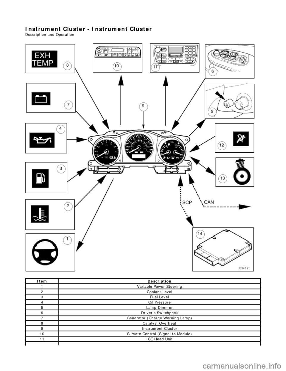
Instrument Cluster - Instrument Cluster
Description and Operation
ItemDescription
1Variable Power Steering
2Coolant Level
3Fuel Level
4Oil Pressure
5Lamp Dimmer
6Driver's Switchpack
7Generator (Charge Warning Lamp)
8Catalyst Overheat
9Instrument Cluster
10Climate Control (Signal to Module)
11ICE Head Unit
Page 2381 of 2490
The body is pre-treated to ensure high resistance to corrosion and stone chip dama ge. Prior to the first major pre-treatment process, the body shell is high-pressure washed to remove any metal dust and residual oil.
The first major pre-treatment process consists of phosphate and electro-paint deposition, which together with zinc coating,
forms the basis of the corrosion protection. This process includes high pressure knock-off, alkali de-greasing, zinc phosphate
conversion of body steel (dissolving iron and coating with zinc phosphate crystals), trivalent chrome rinsing and
demineralized water rinsing, seal ing all chemicals and impurities.
Both dip and spray techniques are employed and the bodies are submerged to the waistline during the first and third rinses
of the main phosphate clean. Chemical strengths and soluti on temperatures are continuously monitored and accurately
controlled throughout the process.
An 80% water primer is then cathodic elec tro-deposition applied to the thoroughly cleansed bodies in a uniform 'sag-free'
film 18 to 32 micron thick. Optimum durabi lity of the electroprimer is achieved by finally curing in a stoving oven at 165 °C
for a period of 20 minutes.
All underbody seams of the fully primed bo dies are then manually sealed, to prevent water and dust ingress into the vehicle
and to enhance corrosion protection.
An 800 to 1000 g/m2 PVC coating is semi-automatic airless sp ray applied to the underside of the main floor panels, trunk
floor and rear wheel arches (ref. illustration above).
The upper panels of primed and external ly sealed bodyshells are next lightly scuffed to remove imperfections and a PVC
coating is applied to all internal seams by an airless spray technique. A PVC bead seal is also applied to the doors, hood and
trunk clinch joints.
Following anti-corrosion, sealing and primin g treatment, the bodies enter the first stage of 'cosmetic' painting. This consists
of the application of two coats of a highly chip resistant po lyester surfacer, employing high voltage electrostatic 'spinning
bells', to achieve a final film thickness of 35 to 50 micron. Between surfacer coats, a polyurethane coat is automatically
applied to the sills to impart even greater resistance to stone chipping.
All interior panels are then painted us ing a color keyed sealer, wet-on-wet wi th a surfacer material, after which the
bodyshells are stoved at 160 °C for a period of 20 minutes. Further protection agai nst corrosion is provided by a medium
solids black pigmented wax which is airless spray applied to vehicle undersides.
Wax Injected Box Sections
Critical body box-sections are si milarly protected by spray injecting a high solids wax. This is then re-flowed at 70 to 90 °C
to achieve optimum seam/joint penetratio n and form a resilient and durable internal coating (ref. illustration above).
After full wet sanding, rinsing and drying to provide a good su bstrate, a color-keyed semi-matt sealer co at is applied using
electrostatic bells to achieve a film build of 25 to 35 micron . The bodies are then stoved for a further 20 minutes at a
temperature of 145 °C and subjected to a local 'seek-and-find' de -nib operation prior to the final two coat process. The final
top coat finish is achieved by using poly ester base coat colors and an acrylic sag resistant clear coat. This clear over base
(COB) process produces a high gloss, durabl e paint finish with a film thickness of 50 to 65 micron, which is finally cured at a
temperature of 135°C for 20 minutes.
The Munsell three dimensional system of color management is em ployed to achieve highly accurate control of vehicle colors.
This system ensures that paint pigmentations are accurately maintained and facilitates vigorous final checking of finished
vehicles for color match. The hu e of individual panels such as trunk lids, doors and hoods is in some instances adjusted to
offset the effects of differing light angles. Where applicable, coachlines are manually applied and radiant heat cured on the
completed and valeted vehicle prior to hand spray applic ation of a protective wax coat.
Introduction
All repairs, whether structural or cosmetic must return the vehicle to the original manufactured condition with regard to
occupant safety, dimensional accuracy, fi nish and corrosion protection, and ensure continuation of the Paint Surface and
Corrosion warranty where applicable.
Similarly, repaired vehicles must be fu lly checked, and where appropriate reset, with regard to steering, suspension,
braking, and occupant restraint systems.
Page 2383 of 2490
Paint
The inhalation of sprays, fumes, or dust during paint application or sanding processes should always be avoided. Ensure
that there is efficient ventilation / extrac tion at all times. Paint spraying should be confined as far as possible to spray
booths. Personnel with a history of asth ma should not be employed in any process involving the use of isocyanates.
Operators working in a spray booth where isocyanate material is present must use air-fed breathing equipment with air
supplied to the visor at the re commended pressure and filtered to remove oil, water, and fumes. Operators involved in
handling mixing or spraying should wear protective clothing including gloves and goggles, to avoid skin and eye contact.
Particle masks or canister type respir atosr should be worn when sanding.
Applied Heat
When welding, flame cutting, brazing etc, the operator shou ld use as appropriate, goggles, mask / fume extractor and
flameproof protective clothing. It is especially important when working with polyurethane compounds to use air-fed
breathing equipment. Appropriat e fire fighting equipment and personnel trai ned in its use must always be available.
Metal Repair
Appropriate eye and hand protection should be worn when sanding, drilling, cutting, chiselling, flatting or welding. Face
masks or air-fed visors should also be wo rn when sanding or flatting either body solder or fillers. On completion of a
soldering operation, swarf must be re moved from the work area and the operat or must wash his hands thoroughly.
GENERAL REPAIR NOTES
The following advice should be noted before any repair work is carried out.
Disconnect the vehicle battery gr ound lead (disconnect the alternator where electric welding is used) and take note of the
reconnection procedures as detailed in 86.15.15.
Where structural parts are straightened or renewed, a body alignment / straightening jig must be used. The application of
heat, especially excessive heat, reduces the strength of steels, where appropriate therefore, structural sections should be
straightened by cold processes.
Repairs may only be carried out successful ly, and any warranties protected, if genuine Jaguar replacement parts and Jaguar
approved materials are used.
The correct tools, procedures and facilities must always be us ed. The quality of the work must not be compromised by using
inappropriate methods or equipment.
All trim and electrical components in the locality of the repair must be removed or disconnected prior to panel removal /
replacement; this is especially important where hollow sectio ns may contain harnesses, tubes or foam, see section A4.3.5.
WARNING: DO NOT WORK IN THE VICINITY OF A LIVE AIR BAG, REMOVE IT COMPLETELY. READ WORKING
PRACTICES AIR BAG, SECTION 20. ANY SEAT BELT WHICH HAS BEEN WORN IN AN ACCIDENT MUST BE RENEWED.
CAUTION: Electric arc welding should not be used on Jaguar vehicles. The high voltages produced by this process will
cause irreparable damage to the electric al control and microprocessor systems.
The following welding and gas processes are the only ones recommended by Jaguar Cars Ltd.
Welding and Gas Processes
Resistance spot welding, MIG welding and all gas processes may only be carried out on bare, unpainted or unplated metal.
The flanges of panels to be welded toge ther, must be clean, corrosion free and tr eated as appropriate, with either weld-
through primer or inter-weld sealer. Only materials and processes specified in the 'Body Sealing and Preservation Manual'
should be used in the relevant application areas detailed in this section. Refer to 'Zinc Coated Panels' Section