1998 JAGUAR X308 heating
[x] Cancel search: heatingPage 1760 of 2490
Symp
tom #5
Sy
m
ptom #5
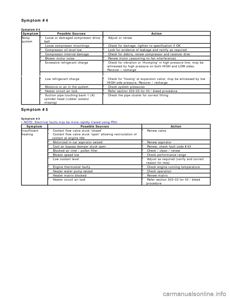
Low r
e
frigerant charge
*
Check f or 'hissi
ng' at expansion
valve; may be witnessed by low
HIGH side pressure. Recover / recharge
*
Moi
s
ture or air in the system
*
Chec k syst
em pressures
*
Heat er ci
rcuit air-lock
*
R e
fer section 303-03 for fill / bleed procedure
*
Suct ion
pipe touching bank 1 (A)
cylinder head (rubber isolator
missing)
*
Check the pi
pe cluster for correct fitti
ng
*
• NOTE: Electrical faults may be more rapidly traced using PDU
Sym
ptom
Possib
l
e Sources
Acti
o
n
Insuffi
ci
ent
heating
Coo l
ant flow valve stuck 'closed'
Coolant flow valve stuck 'open' allowing recirculation of
coolant at engine idle
*
*
Re
new v
alve
*
Motorized in-car aspirator sei zed
*R e
new aspirator
*
Coo l
air bypass damper stuck open
*
Re new,
check fault code #43
*
B l
ocked air inlet / pollen filter
*
Chec k / cl
ean / renew
*
B l
ower speed low
*
Check performance range
*
Low cool ant
level
*
Adjust as req u
ired (verify and correct
reason for loss)
*
Engine
t
hermostat faulty
*
Check engine r u
nning temperature
*
Heater water pump seized
*Chec k op
eration
*
Heater ma trix
blocked
*
Re new m
atrix
*
Heater circui t
air-lock
*
R e
fer section 303-03 for fill / bleed
procedure
*
Sym
p
tom #4
Sym
ptom #4
Sy
m
ptom
Possib
l
e Sources
Acti
o
n
No
i
sy
system
Loose or damaged compressor drive
belt
*Adjust or r
e
new
*
Loose compressor mountings
*Check f o
r damage, tighten to specification if OK
*
Compressor oil level l
ow
*
Look for evidence of l
eakag
e and rectify as required
*
Compressor internal dama ge
*Check f o
r debris, renew compressor and receiver drier
*
B l
ower motor noise
*
Re new m
otor (assuming no fan interference)
*
Excessive refrige rant charge
*Check f o
r vibration or 'thumping'
in high pressure line; may be
witnessed by high pressure on both HIGH and LOW sides.
Recover / recharge
*
Page 1783 of 2490
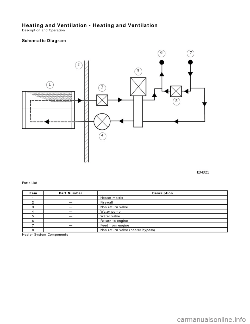
Heating and Ventilation - Heating and Ventilation
Description and Operation
Schematic Diagram
Parts List
Heater System Components
ItemPart NumberDescription
1—Heater matrix
2—Firewall
3—Non return valve
4—Water pump
5—Water valve
6—Return to engine
7—Feed from engine
8—Non return valve (heater bypass)
Page 1785 of 2490
Engine speed (valve closed with the engine not running) Demand (set) temperature In-car temperature sensor Solar sensor
Re-heating of the refrigerated air is contro lled by the time that the water valve is open (i.e. not energised) over a six secon d
interval. The duty cycle of the water valve, the time open / time closed, is controlled by the A/CCM.
Maximum heating demand will cause the water valve to be fu lly open (not energised) to allow maximum coolant flow
through the heater matrix.
At Maximum cooling, the water va lve will be fully closed (energised) to prevent hot (engine temperature) coolant entering
the heater circuit; the pump however will continue to circulate coolant through both the heater matrix and water valve
bypass.
The water valve defaults open when the ignition is OFF.
Under engine stall conditions, when ignition is ON, the water valve will be open.
Water Pump Assembly
Located in the same area as the water valve, the water pump continually circulates coolant through the heater matrix
except when the conditions below apply:
The engine coolant is below 16°C. The ignition is OFF. Under engine stall conditions, when ignition is ON. Control panel OFF
Non return valves
The heater bypass hose has a non-return valve, located between the engine feed and return hoses. The valve prevents the
water pump from recirculating coolant fro m the heater at low engine speeds.
The flow indicator arrow embossed on the valve bo dy MUST point towards the coolant header tank.
CAUTION: Coolant flow will be compromi sed if either valve is fitted incorrectly. Observe the correct direction.
A second non-return valve is located betw een the water pump and water valve. This valve prevents hot coolant from flowing
into the heater with the engine switched off. The flow indicator arrow MUST point towards the water pump.
Heater feed and return hoses
The heater feed and return hoses are connected to the engine feed and return hoses by 'Quick-Fit' connection unions. The
feed hose has a Norma R20 connector and the return hose a Norma push and seal connector. The coolant system bleed
joints have Cobra clamps. All remaining hose connections have spring band hose clamps.
The engine feed hose is connected to the engine bypass hous ing and the engine return hose is connected to the engine
water pump.
Clamp Identification
Page 1787 of 2490
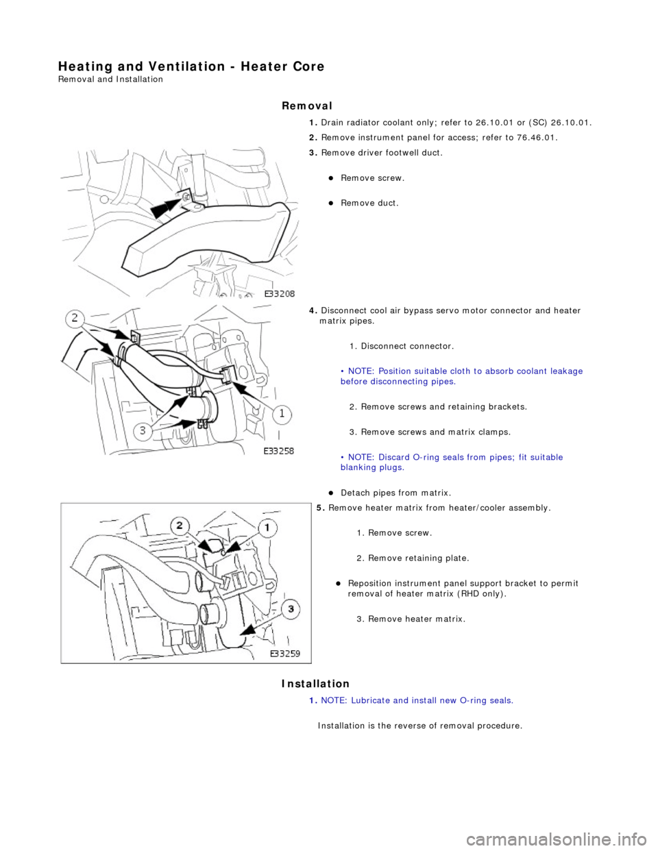
Heating and Ventilation - Heater Core
Removal and Installation
Removal
Installation
1.
Drain radiator coolant only; re fer to 26.10.01 or (SC) 26.10.01.
2. Remove instrument panel for access; refer to 76.46.01.
3. Remove driver footwell duct.
Remove screw.
Remove duct.
4. Disconnect cool air bypass serv o motor connector and heater
matrix pipes.
1. Disconnect connector.
• NOTE: Position suitable clot h to absorb coolant leakage
before disconnecting pipes.
2. Remove screws and retaining brackets.
3. Remove screws and matrix clamps.
• NOTE: Discard O-ring seals from pipes; fit suitable
blanking plugs.
Detach pipes from matrix.
5. Remove heater matrix from heater/cooler assembly.
1. Remove screw.
2. Remove retaining plate.
Reposition instrument panel support bracket to permit
removal of heater matrix (RHD only).
3. Remove heater matrix.
1. NOTE: Lubricate and install new O-ring seals.
Installation is the reverse of removal procedure.
Page 1788 of 2490
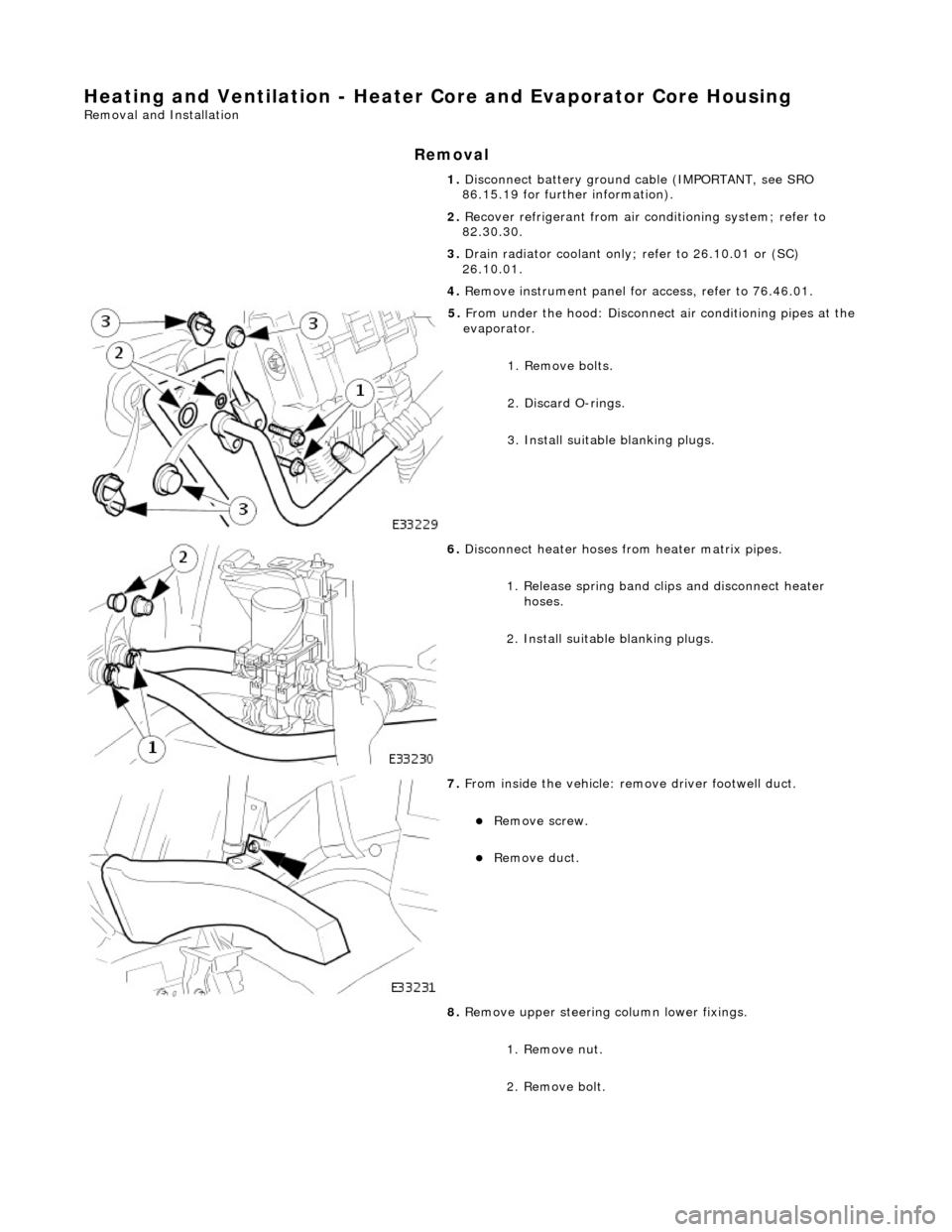
Heating and Ventilation - Heater Core and Evaporator Core Housing
Removal and Installation
Removal
1. Disconnect battery ground cable (IMPORTANT, see SRO
86.15.19 for further information).
2. Recover refrigerant from air co nditioning system; refer to
82.30.30.
3. Drain radiator coolant only; refer to 26.10.01 or (SC)
26.10.01.
4. Remove instrument panel for access, refer to 76.46.01.
5. From under the hood: Disconnect air conditioning pipes at the
evaporator.
1. Remove bolts.
2. Discard O-rings.
3. Install suitable blanking plugs.
6. Disconnect heater hoses from heater matrix pipes.
1. Release spring band clips and disconnect heater hoses.
2. Install suitable blanking plugs.
7. From inside the vehicle: re move driver footwell duct.
Remove screw.
Remove duct.
8. Remove upper steering column lower fixings.
1. Remove nut.
2. Remove bolt.
Page 1799 of 2490
Twin blower assemblies Center mounted evaporator, heater and air distribution unit Electric solenoid water valve controlled heating Electric water pump assembly Servo motor driven air distribution flaps Dedicated side glass defrost / demist vents External temperature sensor Motorised in-car aspirator Solar sensor
Electronic Control Panel
Liquid Crystal Display (LCD) Digital temperature display Manual fan speed level External temperature display Celsius / Fahrenheit selection Heated windshield switch (where fitted) Heated backlight switch Defrost switch Manual airflow distribution overrides (4) Access to self diagnostic system and error codes
Sensors
External ambient temperature sensor Motorized in-car aspirator Heater matrix temperature sensor Evaporator temperature sensor Solar sensor
These sensors feedback information to the Air Conditioning Control Module (A/CCM) which automatically adjusts air
temperature, airflow volume and distributi on from the air conditioning unit to maintain a stable passenger compartment
average temperature under changing weather conditions.
Major Components
Page 1825 of 2490
LO demands the maximum COOLING performance from the system with the blowers operating automatically at maximum
speed.
HI demands the maximum HEATING performance from the system with the blowers operating automatically at maximum
speed.
Pressing and holding either temperature selection button co ntinuously changes the setting temperature by steps of 1°,
every 0.4 seconds.
• NOTE: The interior temperature does not change when the temperature scale is changed between Celsius and Fahrenheit,
however the temperature display will chan ge to the nearest equivalent number.
Examples:
17C 61F 17C 66F 19C 66F
• NOTE: When operating in HI or LO mode and the AUTO butt on is pressed, the system will adopt the nearest automatic
control temperature setting:
LO AUTO DISPLAY INDICATES 17° C or 61° F HI AUTO DISPLAY INDICATES 31° C or 90° F
• NOTE: When switching the system on us ing the AUTO button, the system will display the previous temperature setting,
except under the following conditions:
LO, system OFF, auto display indicates 17° C or 61° F HI, system OFF, auto display indicates 31° C or 90° F
17. 17. Face
Pressing this button will direct all airflow to the center and side face vents only; pressing again will return the system to
automatic control mode.
• NOTE: When in AUTO mode and in a hot c limate, a bleed of cold air is delivered to foot level. This bleed automatically
shuts off when the inte rior temperature has cooled sufficiently.
18. 18. Bi-Level
This push-on / push-off button will direct air to the center and side face vent s and the front footwells. Pressing the button
(off) will return the system to automatic control mode.
19. 19. Foot
This push-on / push-off button will direct the majority of airflow to the front footwells with a small bleed of air to the fron t
and side screens. Pressing the button (off) will return the system to automatic control mode.
20. 20. Demist
Pressing this button will direct air to the front and side screens and the front foot wells. Pressing the button (off) will return
the system to automatic control mode.
Fascia Air Outlets
90
HIHI
Page 1826 of 2490
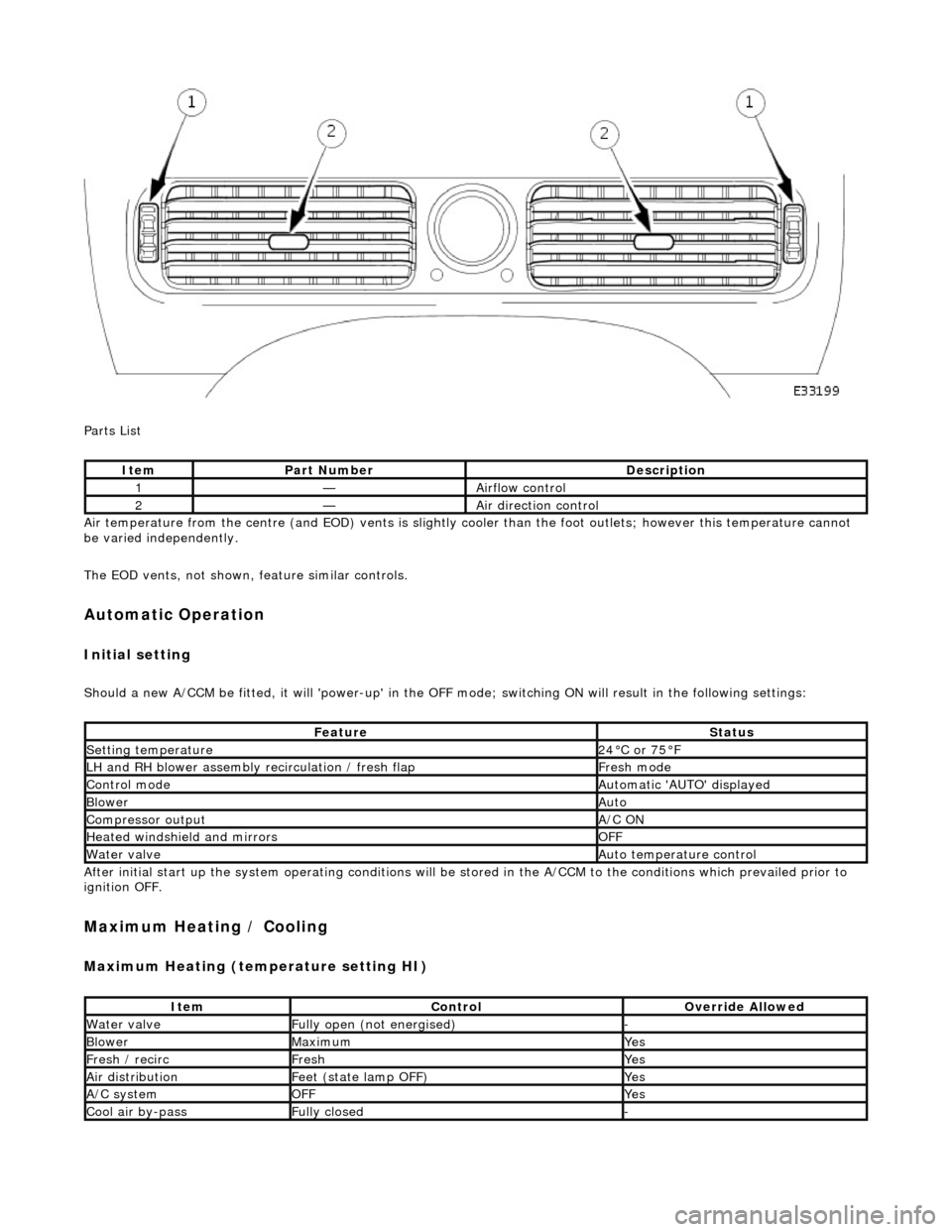
Parts List
Air temperature from the centre (and EOD) vents is slightly cooler than the foot outlets; however this temperature cannot
be varied independently.
The EOD vents, not shown, feature similar controls.
Automatic Operation
Initial setting
Should a new A/CCM be fitted, it will 'power-up' in the OFF mode; switching ON will result in the following settings:
After initial start up the system operating conditions will be st ored in the A/CCM to the conditions which prevailed prior to
ignition OFF.
Maximum Heating / Cooling
Maximum Heating (temperature setting HI)
ItemPart NumberDescription
1—Airflow control
2—Air direction control
FeatureStatus
Setting temperature24°C or 75°F
LH and RH blower assembly recirculation / fresh flapFresh mode
Control modeAutomatic 'AUTO' displayed
BlowerAuto
Compressor outputA/C ON
Heated windshield and mirrorsOFF
Water valveAuto temperature control
ItemControlOverride Allowed
Water valveFully open (not energised)-
BlowerMaximumYes
Fresh / recircFreshYes
Air distributionFeet (state lamp OFF)Yes
A/C systemOFFYes
Cool air by-passFully closed-