Page 1773 of 2490
Ai
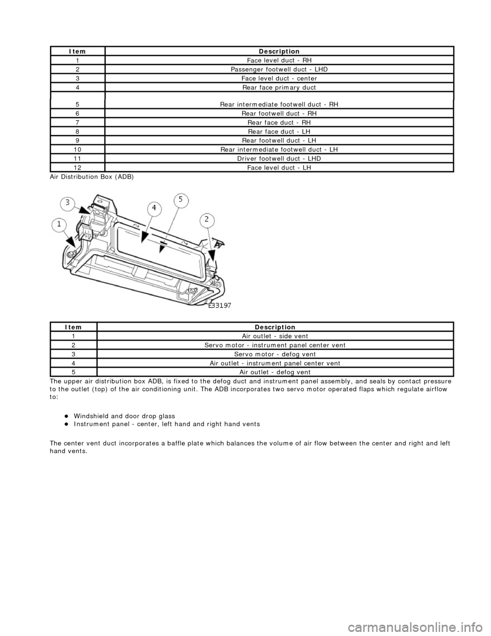
r Distribution Box (ADB)
The upper air distribution box ADB, is fixed to the defog duct and instrument panel assembly, and seals by contact pressure
to the outlet (top) of the air conditioning unit. The ADB inco rporates two servo motor operated flaps which regulate airflow
to:
Windshield and door drop
glass
Instrument panel
- center, left
hand and right hand vents
The center vent duct incorporat es a baffle plate which balances the volume of air flow between the center and right and left
hand vents.
5R
ear intermediate footwell duct - RH
6R
ear footwell duct - RH
7R
ear face duct - RH
8R
ear face duct - LH
9R
ear footwell duct - LH
10R
ear intermediate footwell duct - LH
11D
river footwell duct - LHD
12Fac
e level duct -
LH
It
em
De
scription
1Ai
r outlet - side vent
2Servo motor -
instrume
nt panel center vent
3Servo motor -
defog vent
4Ai
r outlet - instrume
nt panel center vent
5Ai
r outlet - defog vent
It
em
De
scription
1Fac
e level duct - RH
2Passenger footwel
l duct - LHD
3Fac
e level duct - center
4Rear
face primary duct
Page 1799 of 2490
Twin blower assemblies Center mounted evaporator, heater and air distribution unit Electric solenoid water valve controlled heating Electric water pump assembly Servo motor driven air distribution flaps Dedicated side glass defrost / demist vents External temperature sensor Motorised in-car aspirator Solar sensor
Electronic Control Panel
Liquid Crystal Display (LCD) Digital temperature display Manual fan speed level External temperature display Celsius / Fahrenheit selection Heated windshield switch (where fitted) Heated backlight switch Defrost switch Manual airflow distribution overrides (4) Access to self diagnostic system and error codes
Sensors
External ambient temperature sensor Motorized in-car aspirator Heater matrix temperature sensor Evaporator temperature sensor Solar sensor
These sensors feedback information to the Air Conditioning Control Module (A/CCM) which automatically adjusts air
temperature, airflow volume and distributi on from the air conditioning unit to maintain a stable passenger compartment
average temperature under changing weather conditions.
Major Components
Page 1823 of 2490
8.8. Automatic
Symbol indicates when the control of , temperature, fan speed and air distribution are all in Auto mode.
9. 9. External
There are two modes of external ambient temperature selection;
Quick Display. Pressing the button for <1.5 seconds (con firmed by a single bleep) will display the external
temperature for 4 seconds.
Continuous Display. Pressing and holding the button fo r >1.5 seconds (confirmed by two beeps) displays the
external ambient temperature continuously, the value of which will be updated every 4 seconds given that vehicle
road speed is > 25 km/h. Pressing the button again fo r <1.5 seconds resets to the previous display.
• NOTE: Continuous external temperature display will be cancel led when the ignition is switched OFF but not during engine
cranking.
10. 10. A/C
This push-on / push-off button will either select or deselect (as indicated by the state lamp) the refrigeration system.
The refrigeration system is automatically engaged when the Auto button is pressed.
• NOTE: Interior misting of screens may be reduced by continuous operation of th e refrigeration system.
11. 11. Auto
When selected and the state lamp lit, A/C mode will be operat ional and control of vent outlet temperature, fans speed and
air distribution will be automatic.
AUTO mode will disengage should manual air distribution or defrost buttons be operated or the manual fan speed knob be
rotated.
• NOTE: Automatic temperature control is constantly main tained irrespective of selected manual overrides.
12. 12. Defrost
Push-on push-off button, which when engaged will direct all air to the front and side glass at maximum fan speed. The
heated windshield (if fitted) will also be energized for a timed cycle of 6,5 minute s, but may be cancelled by pressing the
HEATED WINDSHIELD (F) button. Pressing 'DEF' again will retu rn to the last setting with automatic temperature control
being maintained.
Directing warm and humid air onto a cold screen can produce interior misting of screens. Operating the climate control
system without the refrigerati on system operating will exacerbate this problem.
• NOTE: Directing cold air onto the screen in warm humid conditions can produce external condensation.
13. 13. Heated Windshield (F)
Pressing the heated windshield button (whe re fitted) will energize the electrically heated windshield elements for a timed
cycle of 6,5 minutes; pressing the button again will cancel the request. Should the engine stall or the ignition be turned
OFF, the timer will be cleare d and the function cancelled.
• NOTE: The heated windshield may be activated with the cl imate control system OFF but the engine must be running.
In very cold ambient temperatures, icing of the interior of the glass is possible when the climate control system is operating
in AUTO mode; to reduce this poss ibility the A/CCM provides automatic operation of the heated windshield.
With the following conditions met, the heated windshield will automatically energize but the state lamp will NOT be lit.
Page 1826 of 2490
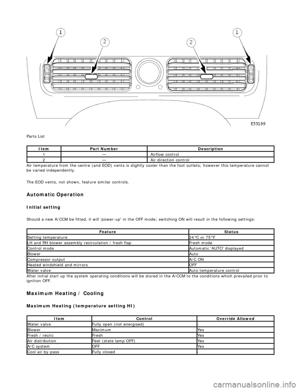
Parts List
Air temperature from the centre (and EOD) vents is slightly cooler than the foot outlets; however this temperature cannot
be varied independently.
The EOD vents, not shown, feature similar controls.
Automatic Operation
Initial setting
Should a new A/CCM be fitted, it will 'power-up' in the OFF mode; switching ON will result in the following settings:
After initial start up the system operating conditions will be st ored in the A/CCM to the conditions which prevailed prior to
ignition OFF.
Maximum Heating / Cooling
Maximum Heating (temperature setting HI)
ItemPart NumberDescription
1—Airflow control
2—Air direction control
FeatureStatus
Setting temperature24°C or 75°F
LH and RH blower assembly recirculation / fresh flapFresh mode
Control modeAutomatic 'AUTO' displayed
BlowerAuto
Compressor outputA/C ON
Heated windshield and mirrorsOFF
Water valveAuto temperature control
ItemControlOverride Allowed
Water valveFully open (not energised)-
BlowerMaximumYes
Fresh / recircFreshYes
Air distributionFeet (state lamp OFF)Yes
A/C systemOFFYes
Cool air by-passFully closed-
Page 1828 of 2490
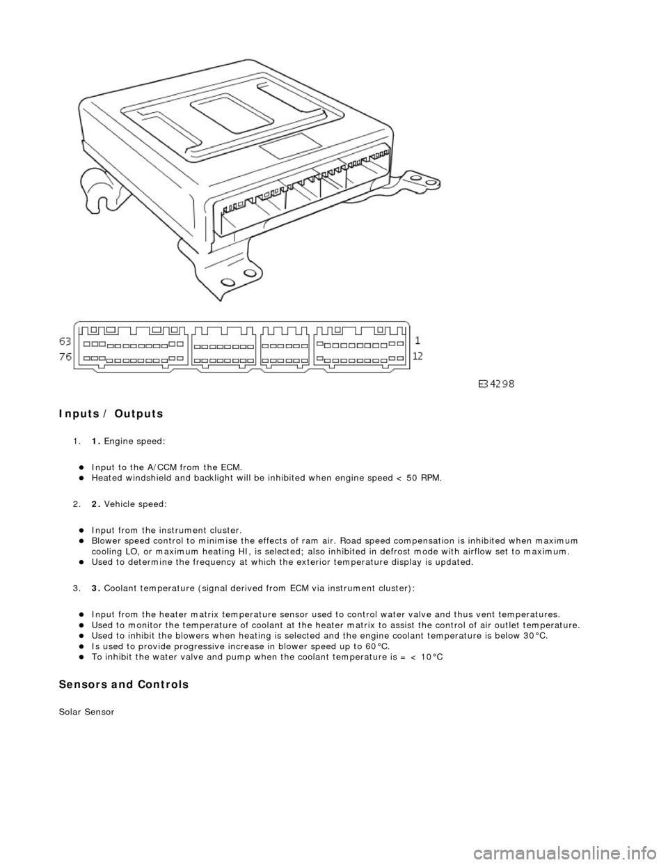
Inputs / Outputs
1.1. Engine speed:
Input to the A/CCM from the ECM. Heated windshield and backli ght will be inhibited when engine speed < 50 RPM.
2. 2. Vehicle speed:
Input from the instru ment cluster. Blower speed control to minimise the effects of ram ai r. Road speed compensation is inhibited when maximum
cooling LO, or maximum heating HI, is selected; also inhi bited in defrost mode with airflow set to maximum.
Used to determine the frequency at which the exterior temperature display is updated.
3. 3. Coolant temperature (signal derived from ECM via instrument cluster):
Input from the heater matrix temperature sensor used to control water valve and thus vent temperatures. Used to monitor the temperature of coolant at the heater matrix to assist the control of air outlet temperature. Used to inhibit the blowers when heating is selected and the engine coolant temperature is below 30°C. Is used to provide progressive increase in blower speed up to 60°C. To inhibit the water valve and pump when the coolant temperature is = < 10°C
Sensors and Controls
Solar Sensor
Page 1833 of 2490
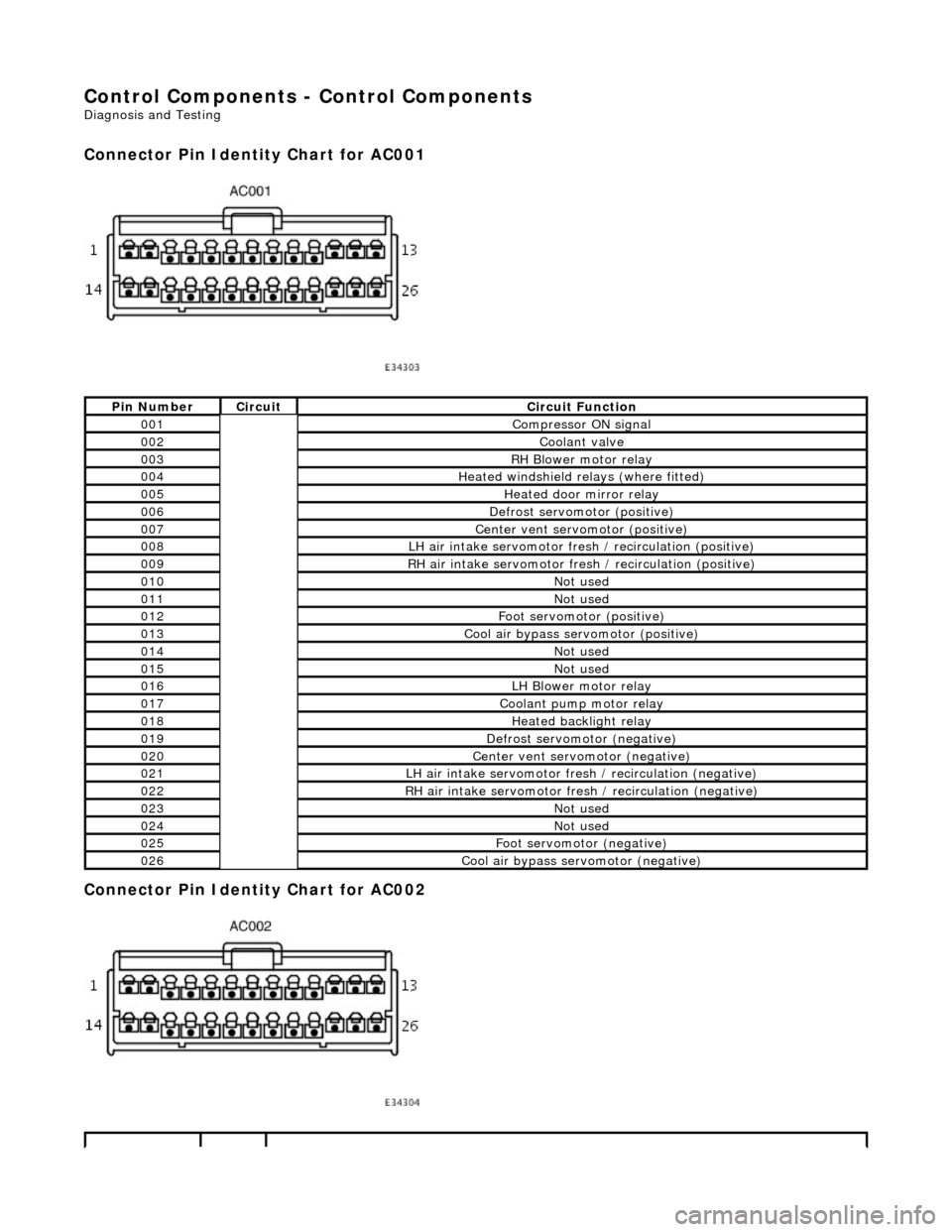
Control Components - Control Components
Diagnosis and Testing
Connector Pin Identity Chart for AC001
Connector Pin Identity Chart for AC002
Pin NumberCircuitCircuit Function
001Compressor ON signal
002Coolant valve
003RH Blower motor relay
004Heated windshield relays (where fitted)
005Heated door mirror relay
006Defrost servomotor (positive)
007Center vent servomotor (positive)
008LH air intake servomotor fre sh / recirculation (positive)
009RH air intake servomotor fresh / recirculation (positive)
010Not used
011Not used
012Foot servomotor (positive)
013Cool air bypass servomotor (positive)
014Not used
015Not used
016LH Blower motor relay
017Coolant pump motor relay
018Heated backlight relay
019Defrost servomotor (negative)
020Center vent servomotor (negative)
021LH air intake servomotor fresh / recirculation (negative)
022RH air intake servomotor fresh / recirculation (negative)
023Not used
024Not used
025Foot servomotor (negative)
026Cool air bypass servomotor (negative)
Page 1979 of 2490
Engine Management Fuse Box Relay
Engine Compartment - Front Relays
Engine and Transmission Control Module Compartment Relays
Relay NoColorCircuit
1BrownEMS control relay
Relay NoColorCircuit
1BlackWindshield wiper fast/slow
2BlackWindshield wiper on/off
Relay NoColorCircuit
1BlueSC coolant water pump
2BrownFuel injection main
3BrownIgnition coils
4BrownThrottle motor
5BrownStarter solenoid
6BrownAir conditioning compressor clutch
Page 1980 of 2490
Front Firewall Relays
Heelboard Fuse Box Relays - Right hand side
* not illustrated
Heelboard Fuse Box Relays - Left hand side
Relay NoColorCircuit
1BlackWindshield RH heater (where fitted)
2BlackWindshield LH heater (where fitted)
Relay NoColorCircuit
1BlueDoor mirror heater
2BlueAir conditioning RH blower
3BlueLeft rear seat lumbar deflate (where fitted) *
4BrownAuxiliary +
5BlueAir conditioning LH blower
Relay NoColorCircuit
1BrownIgnition +
2VioletDoor mirror fold flat (where fitted)
3VioletAir conditioning isolate
4VioletDoor locks