Page 268 of 2490

wheels
and tires.
Infl
atio
n pressure too high or low.
*
Cor r
ect pressure to specification
*
Uneven ti re wear.
*Re fe
r to Diagnosis and Testing in this section.
*
Wh ee
l and tire assembly imbalance.
*
Balance wheel an d tire assembly.
*
Brake disc imbalan c
e.
*
Check brak e disc co
oling fins for mud and foreign
material. Check for damage or disc heavy spot.
Refer to Section 206-00.
*
Damaged or distor
ted wh
eel.
*
Renew wh eel.
*
Excessive radial run-o
ut of wheel or
tire. Excessive lateral run-out of wheel or
tire.
*
*
Renew wh
eel or tire.
*
Incorrectl y
seated tire.
*
R e
mount the tire.
*
Loose wh eel mo
untings: damaged
wheel studs, whee l nuts, worn or
broken wheel hub face or foreign
material on mounting faces.
*
Tigh
te
n or Renew worn or
damaged parts. Clean
mounting surfaces.
*
De
fe
ctive wheel bearings.
*
Renew worn
or damaged bearing sets: Refer to
Section 204-00.
*
W
a
ter in tires.
*
R e
move water.
*
Damaged wh eel stud
thre
ads.
Sli
d
ing wheel across the wheel studs
during installation. Loose wheel nuts.
*
Renew wh
eel studs.
*
Broken wh eel
studs.
Loose or overti
ght
ened wheel nuts.
*
Renew wh eel studs.
*
C o
rrosion / contamination
streaks from wheel stud
holes.
Loose wh eel
nuts.
*
Chec k com
plete assembly. Renew damaged parts.
Apply correct torque setting.
*
Damaged wh
eel nu
ts.
Loose wh
eel
assembly.
Over-tightened wheel nuts.
*
*
Renew wh
eel nu
ts. Apply correct torque setting.
*
Se ize
d wheel nuts.
Cor
rosion
*
CAUTI O
N: Do not permit lubricant to
contaminate wheel hub stud holes or wheel nut seats.
If corrosion is light, wire brush away corrosion. If
corrosion is excessive renew wheel studs and wheel
nuts. Lubricate th e first three threads of wheel
studs with a graphite based lubricant.
*
Page 269 of 2490
W
heels and Tires - Wheel and Tire
Re
moval and Installation
Remov
al
CAUTI
ON: Do not use heat to loosen a seized wheel nut: heat will change the metal's properties and damage wheel
bearing and brake caliper seals.
I
nstallation
1.
NOTE
: Certain Jaguar wheels are fitted wi
th a hexagon wheel
nut cover
R
emove the cover with the plastic spanner supplied with
the spare wheel jacking equipment.
2. Loosen
, but do not
remove wheel nuts.
3. Raise vehicle and support on st ands. Refer to Section 100-02.
4. R
emove wheel and tire assembly.
1. Remove wheel nuts.
2. Remove wheel.
1. CAUTION: Do not allow grease to contaminate the wheel
stud threads and wheel nut to wh eel mating surface, as this may
cause the nuts to loosen.
• NOTE: To prevent the wheel corroding on to the hub, smear a
thin layer of grease onto the hub mounting face and spigot; and
wheel mounting face and spigot hole.
Page 270 of 2490
Instal
l the wheel an
d tire assembly.
1. Install wheel.
2. Install wheel nuts to secure wheel in position.
3. Lower vehicle.
4. Tighten wheel nuts in a diagonal sequence to:
Steel wh
eel 68-82 Nm.
Al
loy
wheel 88-102 Nm.
Page 273 of 2490

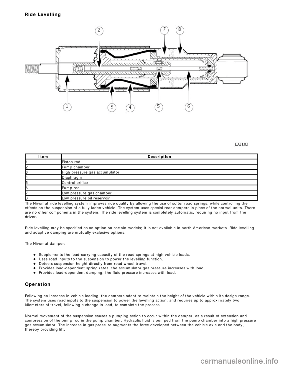
The
Nivomat ride levelling system improves ride quality by al
lowing the use of softer road springs, while controlling the
effects on the suspension of a fully laden vehicle. The system uses special rear dampers in place of the normal units. There
are no other components in th e system. The ride levelling system is comple tely automatic, requiring no input from the
driver.
Ride levelling may be specified as an opti on on certain models; it is not available in north American markets. Ride levelling
and adaptive damping are mu tually exclusive options.
The Nivomat damper:
Su
pplements the load-carrying capacity of th
e road springs at high vehicle loads.
Uses road inputs to the
suspension to power the levelling function.
De
tects suspension height dire
ctly from road wheel travel.
Provi
des load-dependent spring rates; the ac
cumulator gas pressure increases with load.
Pr
ovides load-dependent damping; the fluid pressure increases with load.
Op
eration
F
ollowing an increase in vehicle loading,
the dampers adapt to maintain the height of the vehicle within its design range.
The system uses road inputs to the suspension to power the levelling action, and requires up to approximately two
kilometers of travel, following a change in load, to complete the process.
Normal movement of the suspension caus es a pumping action to occur within the damper, as a result of extension and
compression of the pump rod in the pump chamber. Hydraulic fluid is pumped from the pump cham ber into a high pressure
gas accumulator. The increase in gas pressure augments the force developed between th e vehicle axle and the body,
thereby providing lift.
It
em
De
scription
1Pi
ston rod
2Pum
p chamber
3High
pressure
gas accumulator
4Diaphragm
5Co
ntrol orifice
6Pump rod
7Low pressure gas ch
amber
8Low pressure oil
reservoir
Ride Levelling
Page 276 of 2490

Is hard-wi
red to the instrume
nt cluster message center.
Is hard
-wired to the J1962 diagnostic connector.
Op
era
tion
Th
e
system selects the soft or
firm damper setting according to the current ro ad and driving conditions, to optimise vehicle
ride and handling.
With the vehicle stationary, the dampers are in the firm setting, but will normally switch to the soft setting when the vehicle
exceeds 8 km/h (5 mile/h); all dampers are switched simultaneously.
Sudden movement of the vehicle body, in response to road inputs, is detected by the vertical accelerometers, and the ADCM
switches the dampers to the firm setting to give improved damping of the resultant oscillations.
When cornering forces are detected by th e lateral accelerometer, the ADCM switches the dampers to the firm setting to
reduce the roll rate an d improve wheel control.
After the event has passed, the dampers revert to the soft setting.
When the footbrake is applied, the ADCM re ceives a signal and calculates the rate of vehicle deceleration. If the deceleration
rate is greater than a certain threshold, the dampers are switched to the firm setting to reduce the pitch rate and improve
wheel control.
If a system failure occurs, the ADCM grounds the output line to the instrument cluster message center, which displays a
text warning SUSPENSION FAULT and illuminates the amber warning lamp. Under fault conditions the system always fails to
the firm setting, so that the vehicle will be safe to drive un der all road and driving conditions.
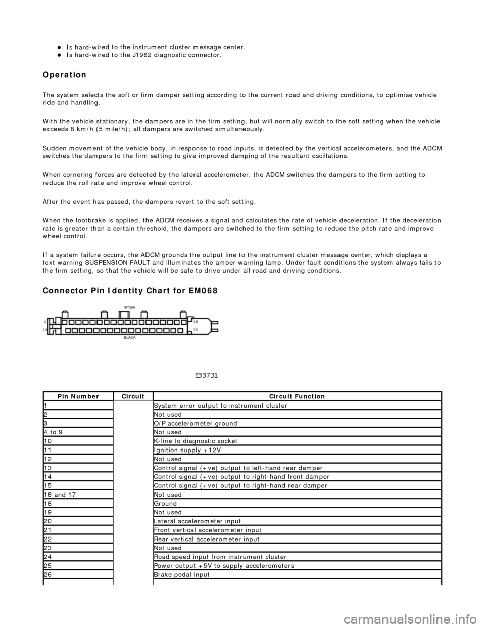
Connector Pin Identity Chart for EM068
Pin
Number
Ci
rcui
t
Circuit Functi
on
1System erro
r output to instrument
cluster
2Not
used
3O/
P a
ccelerometer ground
4 to
9
Not
used
10K-
li
ne to diagnostic socket
11Ignition su
pply +12V
12Not
used
13Control signal (+ve) output
to l
eft-hand rear damper
14Control signal (+ve) output
to right-hand front damp
er
15Control signal (+ve) output
to right-hand rear
damper
16
a
nd 17
No
t
used
18Ground
19No
t
used
20Lateral
accelerometer i
nput
21Front vertical ac
celerometer in
put
22Rear vertical
acce
lerometer input
23No
t
used
24R
o
ad speed input from
instrument cluster
25Power output +5V to suppl y accelerometers
26Brake peda
l input
Page 287 of 2490
R
ear Drive Axle/Differential - Differ
ential Output Shaft End Float Check
Gen
eral Procedures
1.
Di
sconnect the battery ground lead
2. Raise the vehicle for access
3. Mo
unt a dial test indicator (DTI
) to the differential housing with
the probe resting on the axle sh aft flange (the DTI probe must
be parallel to the output shaf t center line and NOT the axle
shaft)
4. Chec
k the end float
Pus
h the wheel / shaft assembly INWARDS
Zero the DTI
P
ull the wheel / shaft assembly OUTWARDS
N
ote the reading
5. Check the specification
0 t
o 0,15 mm GOOD
0,
15 mm + NOT GOOD; Renew the output shaft bearing
Page 288 of 2490
Re
ar Drive Axle/Differential - Axle Shaft
In-v
ehic
le Repair
Remov
a
l
S
p
ecial Tool(s)
Hub remover
2
04-011
Thread protector
JD
1D
/ 7
1. Disc
onnect the battery ground lead.
2. Support the vehicle at the rear and remove the appropriate
rear road wheel.
3. Remove and discard the hub nut, apply the brakes to prevent
rotation.
4. Remove the brake caliper in acco rdance with 70.55.03, but do
not disconnect the hydraulics.
5. Pr
epare the hub carrier.
1. 'Match mark' the hub carr ier fulcrum bolt head and
the carrier.
6. Prepare the hub carrier.
1. Slacken the hub ca rrier fulcrum nut.
2. Disconnect the ABS sensor multiplug at the hub
Page 289 of 2490
carri
er
7. Protect
the driveshaft thread wi
th special tool JD 1D / 7.
8. Wi
thdraw the hub from the axle shaft
8. CAUTION: Take care not to introduce debris into
the hub bearings, or damage the seal
U
sing service tool 204 - 011,
push the axle shaft through
the hub
9. NO
TE: In the wheel-free condition, the axle is in tension and
the flanges will separate as the nuts are withdrawn
Release the axle shaft 1. Remove and discard the (4) nuts axle shaft to differential output shaft
2. Clear the axle shaft from the output flange studs
3. Remove and keep safe the camber shim
10. NOTE: The axle shaft nuts may damage the studs upon
removal; check the thread conditio n by engaging a new nut 2 or 3
threads by hand.
Inspect the output flange studs and renew if there is evidence
of damage / distortion
11. Clean all traces of thread lo cking agent from the hub splines