Page 2024 of 2490
located behind the trunk lid badge.
Occupant Restraints
Inertia reel seat belts with electronically controlled pre-tensioners are installed at the front seats. Supplementary occupant
restraint is provided for driver and front seat passenger by front airbags, and side air bags installed in the outer wing of
each front seat. Standard inertia reel type belts are fitted to all three rear seat positions. The front seat belts are provide d
with height adjuster units which are attached one to each of the 'B' posts. Where emergency locking retractor/automatic
locking retractor seat belts are provided, the belts have two operating modes.The inertia reel mode with emergency locking
retractor is for adult passenge r use only and operates to allow the occupant some freedom of tors o movement under normal
travel conditions.. The static reel mode which prevents belt payout and must be used when a ch ild seat is installed, is
activated by fully extending the belt to engage the ratchet me chanism,.then releasing the belt. Operation of the ratchet will
then be felt and the belt w ill become locked in that position. To revert to in ertia reel (adult passenger) mode, pay the belt
back into the reel to th e fully retracted position.
Body Structure
The XJ8 sedan body is produced in monocoque standard and lo ng wheelbase form. 70% of the body panels are zinc coated
to achieve optimum corrosion protection and a further 8% are constructed in high st rength steels to provide high torsional
strength and passenger impact protection.
Doors
Each front and rear door consists of a we lded, mild steel inner frame and an outer panel. The outer panel is welded to the
waist rail and cheater of the inner frame, then bonded and clinched to fo rm the door assembly. Cosmetic PVC bead is
applied to all clinch joints
Hood
The hood consists of one piece inner an d outer panels clinched and bonded toge ther, with cosmetic bead PVC sealant
applied to all clinch joints. The hood pivo ts at the front on two hinges each secured by bolts to the hood front underside and
the BIW front upper crossmember. Two gas struts secured to the hood by pi vot pins and snap-on couplings, support the
hood in the open position.
Trunk
The trunk lid is of similar construction to the hood, consisting of inner and outer panels clinched and bonded together and
PVC bead sealed. The trunk accommodates the spare wheel, the battery, an electrical carrier containing electrical fuses,
relays and modules and where premium ICE is fitted, a compac t disc auto-changer mounted on body bracketry. Carpet
covered trims line the trunk sides and front inner panel and a po lyurethane rear finisher is secured to the rear panel by
spring clips and fir tree fasteners.
B and C Post Reinforcement
Page 2122 of 2490
Seating - Front Seat
Removal and Installation
Removal
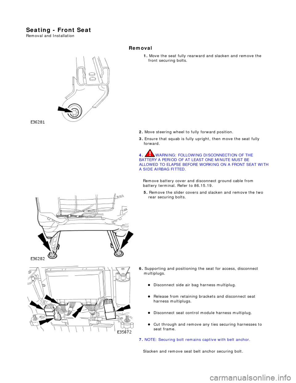
1. Move the seat fully rearward and slacken and remove the
front securing bolts.
2. Move steering wheel to fully forward position.
3. Ensure that squab is fully upright, then move the seat fully
forward.
4. WARNING: FOLLOWING DISCONNECTION OF THE
BATTERY A PERIOD OF AT LEAST ONE MINUTE MUST BE
ALLOWED TO ELAPSE BEFORE WORKING ON A FRONT SEAT WITH
A SIDE AIRBAG FITTED.
Remove battery cover and disc onnect ground cable from
battery terminal. Refer to 86.15.19.
5. Remove the slider covers an d slacken and remove the two
rear securing bolts.
6. Supporting and positioning the seat for access, disconnect
multiplugs.
Disconnect side air bag harness multiplug.
Release from retaining brackets and disconnect seat
harness multiplugs.
Disconnect seat control module harness multiplug.
Cut through and remove any ti es securing harnesses to
seat frame.
7. NOTE: Securing bolt remains captive with belt anchor.
Slacken and remove seat be lt anchor securing bolt.
Page 2173 of 2490
Seating - Rear Seat Track
Removal and Installation
Removal
1. Remove battery cover and disc onnect ground cable from
battery terminal. Refer to 86.15.19.
2. Slacken and remove the two seat cushion front securing bolts
and nuts.
3. Move the seat cushion forward to release it from the two frame
rear tangs.
4. Disconnect the cushion heater harness multiplug and remove
cushion from seat frame.
5. Remove and discard pl astic scrivet securing lower end of side
trim to inner wheela rch stud and withdraw trim from stud.
Page 2306 of 2490
Wipers and Washers - Wipers and Washers
Description and Operation
Windshield Wiper
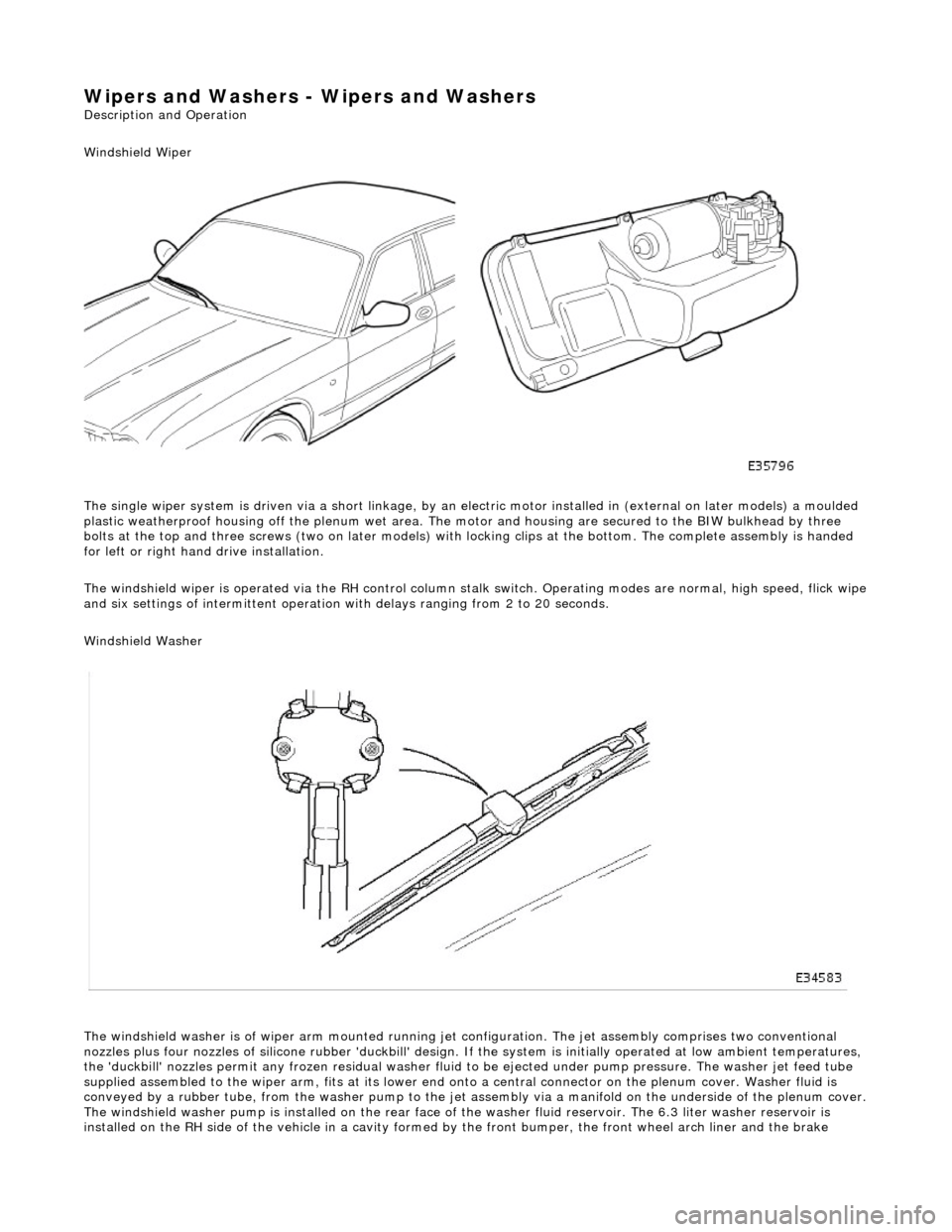
The single wiper system is driven via a sh ort linkage, by an electric motor installed in (external on later models) a moulded
plastic weatherproof housing o ff the plenum wet area. The motor and housing are secured to the BIW bulkhead by three
bolts at the top and three screws (two on later models) with locking clips at the bottom. The complete assembly is handed
for left or right hand drive installation.
The windshield wiper is operated via the RH control column stalk switch. Operating modes are normal, high speed, flick wipe
and six settings of intermittent operation with delays ranging from 2 to 20 seconds.
Windshield Washer
The windshield washer is of wiper arm mounted running jet configuration. The je t assembly comprises two conventional
nozzles plus four nozzles of silicone rubbe r 'duckbill' design. If the system is initially operated at low ambient temperatures ,
the 'duckbill' nozzles permit an y frozen residual washer fluid to be ejected un der pump pressure. The washer jet feed tube
supplied assembled to the wiper ar m, fits at its lower end onto a central connector on the pl enum cover. Washer fluid is
conveyed by a rubber tube, from the washer pump to the jet assembly via a manifold on the underside of the plenum cover.
The windshield washer pump is installed on the rear face of the washer fluid reservoir. The 6.3 liter washer reservoir is
installed on the RH side of th e vehicle in a cavity formed by the front bu mper, the front wheel arch liner and the brake
Page 2315 of 2490
Wipers and Washers - Windshield Washer Reservoir
Removal and Installation
Removal
Installation
1.
Open hood and fit fender cover.
2. Raise front of vehicle and support on stands.
3. Remove RH front wheel.
4. Remove RH front wheel arch li ner. Refer to Section 501-02.
5. Remove front undertray. Refer to Section 501-02.
6. Remove windshield washer and headlamp powerwash pumps
from reservoir. Refer to op erations in this section.
7. Disconnect Low Level indicator mu ltiplug. Refer to operations
in this section.
8. Carefully remove filler cap from reservoir filler neck.
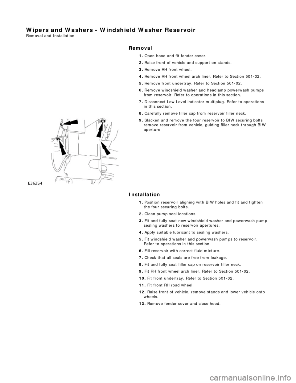
9. Slacken and remove the four re servoir to BIW securing bolts
remove reservoir from vehicle, guiding filler neck through BIW
aperture
1. Position reservoir aligning with BIW holes and fit and tighten
the four securing bolts.
2. Clean pump seal locations.
3. Fit and fully seat new windshie ld washer and powerwash pump
sealing washers to reservoir apertures.
4. Apply suitable lubricant to sealing washers.
5. Fit windshield washer and powerwash pumps to reservoir.
Refer to operations in this section.
6. Fill reservoir with correct fluid mixture.
7. Check that all seals are free from leakage.
8. Fit and fully seat filler cap on reservoir filler neck.
9. Fit RH front wheel arch liner. Refer to Section 501-02.
10. Fit front undertray. Refer to Section 501-02.
11. Fit front RH road wheel.
12. Raise front of vehicle, remove stands and lower vehicle onto
wheels.
13. Remove fender cover and close hood.
Page 2344 of 2490
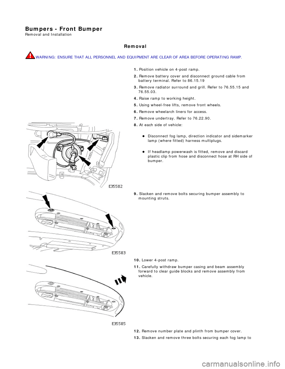
Bumpers - Front Bumper
Removal and Installation
Removal
WARNING: ENSURE THAT ALL PERSONNEL AND EQUIPMENT ARE CLEAR OF AREA BEFORE OPERATING RAMP.
1. Position vehicle on 4-post ramp.
2. Remove battery cover and disc onnect ground cable from
battery terminal. Refer to 86.15.19
3. Remove radiator surround and grill. Refer to 76.55.15 and
76.55.03.
4. Raise ramp to working height.
5. Using wheel-free lifts, remove front wheels.
6. Remove wheelarch liners for access.
7. Remove undertray. Refer to 76.22.90.
8. At each side of vehicle:
Disconnect fog lamp, directio n indicator and sidemarker
lamp (where fitted) harness multiplugs.
If headlamp powerwash is fitted, remove and discard
plastic clip from hose and disconnect hose at RH side of
bumper.
9. Slacken and remove bolts securing bumper assembly to
mounting struts.
10. Lower 4-post ramp.
11. Carefully withdraw bumper casing and beam assembly
forward to clear guide blocks and remove assembly from
vehicle.
12. Remove number plate and plinth from bumper cover.
13. Slacken and remove three bolts securing each fog lamp to
Page 2347 of 2490
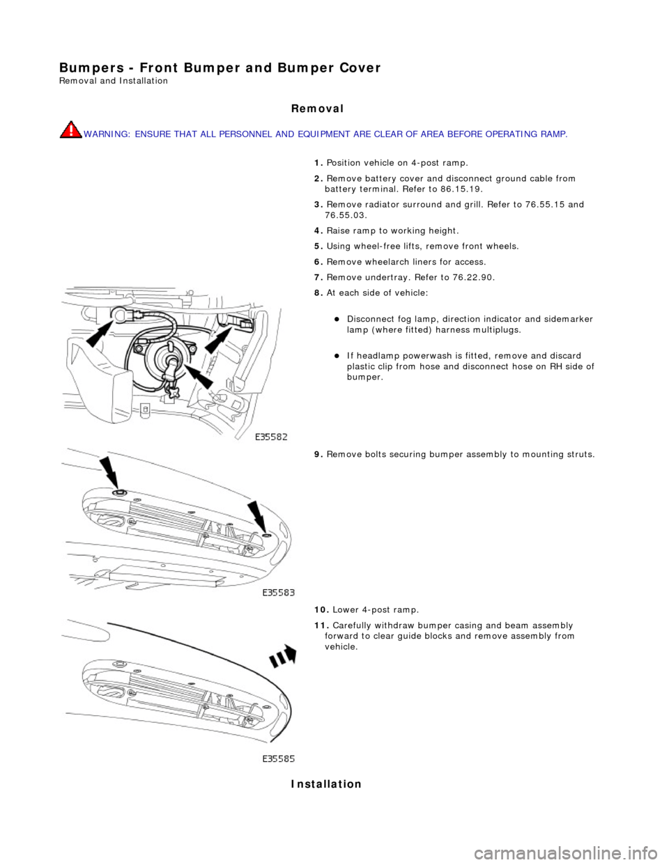
Bumpers - Front Bumper and Bumper Cover
Removal and Installation
Removal
WARNING: ENSURE THAT ALL PERSONNEL AND EQUIPMENT ARE CLEAR OF AREA BEFORE OPERATING RAMP.
Installation
1. Position vehicle on 4-post ramp.
2. Remove battery cover and disc onnect ground cable from
battery terminal. Refer to 86.15.19.
3. Remove radiator surround and grill. Refer to 76.55.15 and
76.55.03.
4. Raise ramp to working height.
5. Using wheel-free lifts, remove front wheels.
6. Remove wheelarch liners for access.
7. Remove undertray. Refer to 76.22.90.
8. At each side of vehicle:
Disconnect fog lamp, directio n indicator and sidemarker
lamp (where fitted) harness multiplugs.
If headlamp powerwash is fitted, remove and discard
plastic clip from hose and disconnect hose on RH side of
bumper.
9. Remove bolts securing bumper assembly to mounting struts.
10. Lower 4-post ramp.
11. Carefully withdraw bumper casing and beam assembly
forward to clear guide blocks and remove assembly from
vehicle.
Page 2348 of 2490
1.
WARNING: ENSURE THAT ALL PERSONNEL AND
EQUIPMENT ARE CLEAR OF AREA BEFORE OPERATING RAMP.
Carefully slide bumper assembly onto fender guide blocks.
2. Raise ramp to working height.
3. Install but do not fully tighten bo lts securing bumper to struts.
4. Check clearance between top of bumper and bottom of fender.
If necessary, remove bumper, adjust guide blocks to achieve
correct clearance and refit bumper.
5. Connect harness multiplugs to foglamps, direction indicators
and where fitted side marker lamps.
6. Install harnesses in retaining clips at each side of cover.
7. Install powerwash hoses to jet assemblies and secure with new
plastic clips. Refer to Section 501.16.
8. Install radiator grill and su rround. refer to 76.55.03 and
76.55.15.
9. Check and as necessary adjust bumper cover to fender,
headlamps and radiator grill surround clearances. Refer to
Description and Operation in this section.
10. Fully tighten bumper assembly to strut securing bolts.
11. Install wheelarch liners.
12. Install undertray. Refer to 76.22.90.
13. Lower 4-post ramp.
14. Install road wheels and lower wheel-free lifts.