Page 2349 of 2490

Bumpers - Front Bumper Cover
Removal and Installation
Removal
WARNING: ENSURE THAT ALL PERSONNEL AND EQUIPMENT ARE CLEAR OF AREA BEFORE OPERATING RAMP.
1. Position vehicle on 4-post ramp.
2. Remove battery cover and disc onnect ground cable from
battery terminal. Refer to 86.15.19.
3. Remove radiator surround and grill. Refer to 76.55.15 and
76.55.03.
4. Raise ramp to working height.
5. Using wheel-free lifts, remove front wheels.
6. Remove wheelarch liners for access.
7. Remove undertray. Refer to 76.22.90.
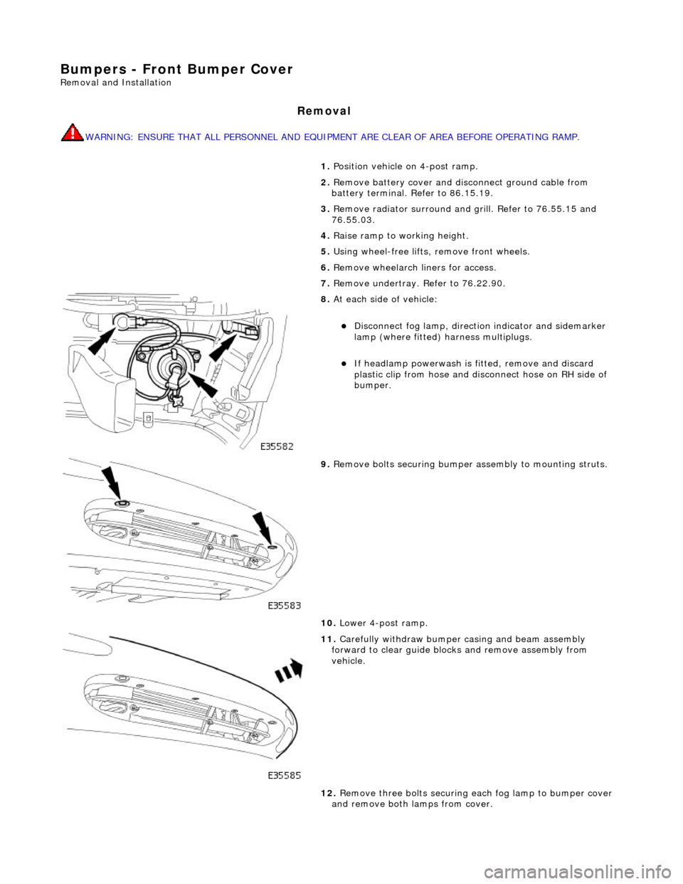
8. At each side of vehicle:
Disconnect fog lamp, directio n indicator and sidemarker
lamp (where fitted) harness multiplugs.
If headlamp powerwash is fitted, remove and discard
plastic clip from hose and disconnect hose on RH side of
bumper.
9. Remove bolts securing bumper assembly to mounting struts.
10. Lower 4-post ramp.
11. Carefully withdraw bumper casing and beam assembly
forward to clear guide blocks and remove assembly from
vehicle.
12. Remove three bolts securing each fog lamp to bumper cover
and remove both lamps from cover.
Page 2366 of 2490
Installation
7. Remove seat squab for access using extension of undisturbed
belts to achieve clearance from inertia reels. Refer to 76.70.38.
8. Slacken and remove two bolts and washer securing inertia reel
assembly to top of squab panel and remove belt assembly from
vehicle.
1. Position inertia reel assembly at top of squab panel and fit and
tighten securing bolts.
2. Pass belt tongue and lower anchor plate through aperture at
top of seat.
3. Fit escutcheon over seat belt an d fit and firmly seat in squab
aperture.
4. Position lower anchor plate at inner wheelarch (seat pan for
centre seat belt) and fit and tighte n securing bolt.
5. Position buckle assembly (and lo wer anchor plate if centre belt)
on seat pan and fit and tighten cable securing bolt.
6. Position and secure rear se at squab. Refer to 76.70.38.
7. Fit rear seat cushion. Refer to 76.70.37
Page 2372 of 2490

Supplemental Restraint System - Driver Air Bag Module
Removal and Installation
Removal
• WARNINGS:
FOLLOWING DISCONNECTION OF THE BATTERY, A PERIOD OF AT LEAST ONE MINUTE MUST BE ALLOWED TO ELAPSE
BEFORE ANY WORK IS CARRIED OUT ON AN AIR BAG MODULE.
FOLLOWING TEN YEARS IN SERVICE, AN AIR BAG MO DULE MUST BE REMOVED AND DISPOSED OF IN THE
APPROVED MANNER, AND A NEW AIR BAG MUST BE FITTED.
AIR BAGS CONTAIN A CHEMICAL IRRITANT. IF AN AIR BAG IS RENEWED, THE ORIGINAL UNIT MUST BE DISPOSED
OF IN ACCORDANCE WITH CURRENT SAFETY PROCEDURES.
IN THE EVENT OF A FAULT RUPTURING THE 10A BATTERY SUPPLY FUSE (F4 LOCATED IN THE FUSE-BOX AT THE
DRIVER'S END OF THE FASCIA), THE FUSE MUST NOT BE RENEWED UNTIL THE AIRBAG/SRS SYSTEM HAS BEEN DE-
ACTIVATED. FUSES OF ANY OTHER VALUE MUST NEVER BE USED, AS THIS CAN CAUSE DISARM FAILURE.
Installation
1. Remove battery cover and disc onnect ground cable from
battery terminal. Refer to 86.15.19.
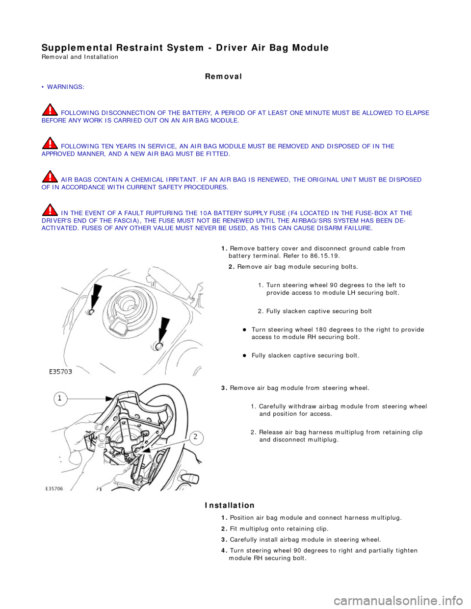
2. Remove air bag module securing bolts.
1. Turn steering wheel 90 degrees to the left to
provide access to module LH securing bolt.
2. Fully slacken captive securing bolt
Turn steering whee l 180 degrees to the right to provide
access to module RH securing bolt.
Fully slacken captive securing bolt.
3. Remove air bag module from steering wheel.
1. Carefully withdraw airbag module from steering wheel
and position for access.
2. Release air bag harness mu ltiplug from retaining clip
and disconnect multiplug.
1. Position air bag module and connect harness multiplug.
2. Fit multiplug onto retaining clip.
3. Carefully install airbag mo dule in steering wheel.
4. Turn steering wheel 90 degrees to right an d partially tighten
module RH securing bolt.
Page 2373 of 2490
5.
Turn steering wheel 90 degrees to left and partially tighten
module LH securing bolt.
6. Repeat steps 3 and 4 to fully ti ghten securing bolts and return
steering wheel to central position.
7. Fit ground cable to battery terminal. Refer to 86.15.15.
Page 2453 of 2490
21. Remove front road wheels. Refer to Section 100-02.
22. Remove crossbeam to engine Hydramount securing bolts.
Remove bolt securing crossbeam to Hydramount.
Fully withdraw bolt into crossbeam insert.
Repeat procedure to remove and withdraw bolt on
opposite side
23. Remove lower nut and bolt from front shock absorber.
Repeat procedure to remove bo lt from opposite side shock
absorber.
24. Slacken but do not remove crossbeam rear nuts.
Slacken crossbeam LH rear mounting nut.
Repeat procedure to slacken crossbeam RH rear mounting
nut.
25. Release lower steering column from pinion shaft.
1. Remove lower steering column nut and bolt.
Move column upwards to release it from pinion shaft.
26. Disconnect steering rack transducer harness front connector.
Release harness connector from body retaining clip.
Disconnect connector.
Page 2485 of 2490
9. Position spacer in the rece ss of each subframe bush.
10. Raise jack to locate subframe bushes on the body tapered
locations.
11. CAUTION: When installing su bframe bracket ensure that wheel speed sensor harness is clear.
Fit suspension subframe mounting-brackets.
1. Position bracket to subframe.
2. Install but do not ti ghten bush center bolt.
3. Install but do not tighten bolts securing bracket to body.
Following same procedure, install mounting bracket on
opposite side.
12. Tighten mounting bracket to body bolts to 80-100Nm.
Following same procedure, ti ghten mounting bracket bolts
on opposite side.