Page 1855 of 2490
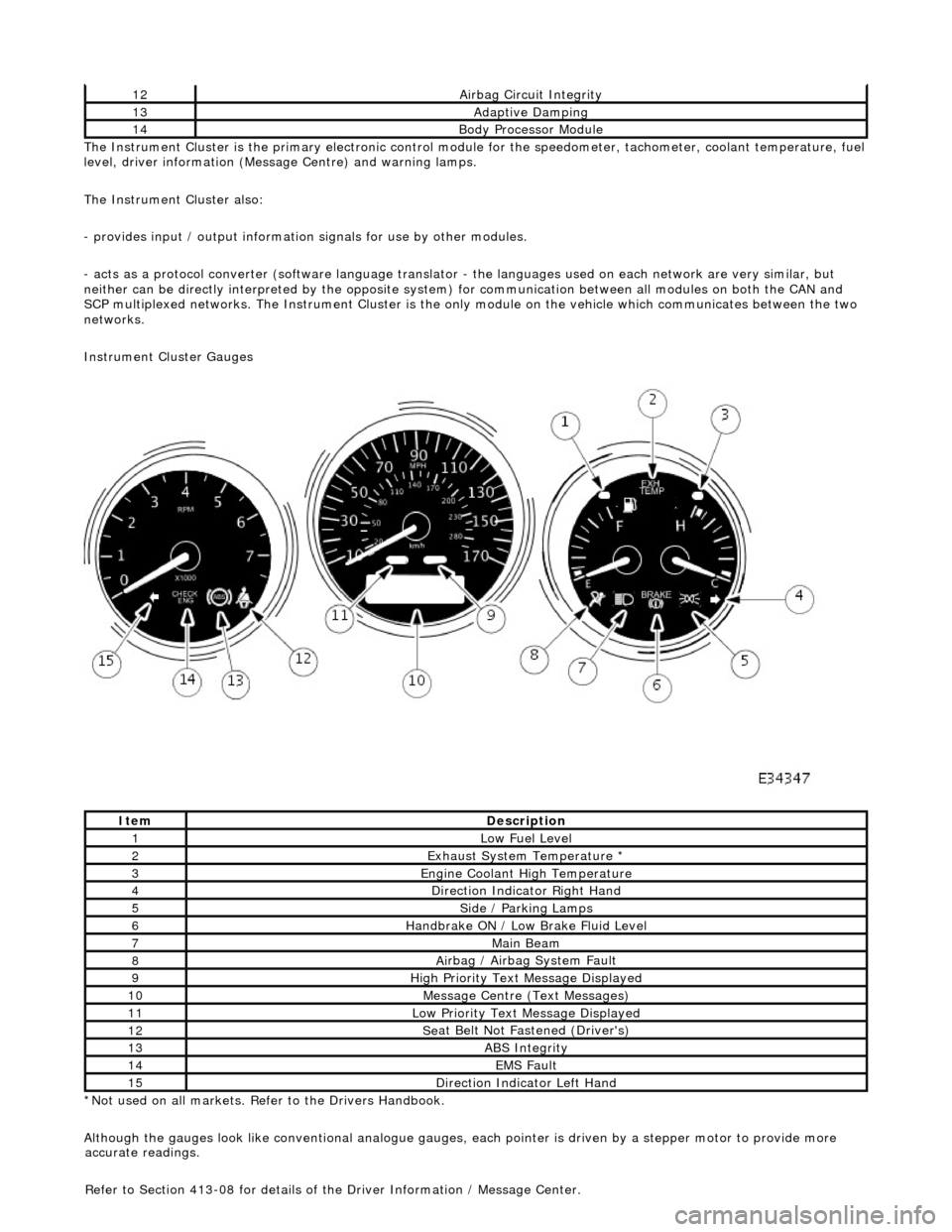
The In
strument Cluster is the primary electronic control module for the speedomete
r, tachometer, coolant temperature, fuel
level, driver information (Message Centre) and warning lamps.
The Instrument Cluster also:
- provides input / output informatio n signals for use by other modules.
- acts as a protocol converter (software language translator - the languages used on each network are very similar, but
neither can be directly interp reted by the opposite system) for communication between all modules on both the CAN and
SCP multiplexed networks. The Instrument Cluster is the only module on the vehicle which communicates between the two
networks.
Instrument Cluster Gauges
*Not used on all markets. Refer to the Drivers Handbook.
Although the gauges look like conventional analogue gauges, each pointer is driven by a stepper motor to provide more
12Ai
rbag Circuit Integrity
13Adaptive Damping
14Body Processor
Module
It
em
De
scription
1Low Fu
el Level
2Exhaus
t System Temperature *
3E
ngine Coolant High Temperature
4Di
rection Indicator Right Hand
5Side
/ Parking Lamps
6Handbrake ON / Low
Bra
ke Fluid Level
7Main
Beam
8Ai
rbag / Airbag System Fault
9Hi
gh Priority Text
Message Displayed
10M
essage Centre (Text Messages)
11Low Pri
ority Text Message Displayed
12Se
at Belt Not Fa
stened (Driver's)
13ABS Integrity
14EMS Fault
15D
irection Indicator Left Hand
accu
rate readings.
Refer to Section 413-08 for details of the Driver Information / Message Center.
Page 1882 of 2490
Generator and Regulator - Generator
Description and Operation
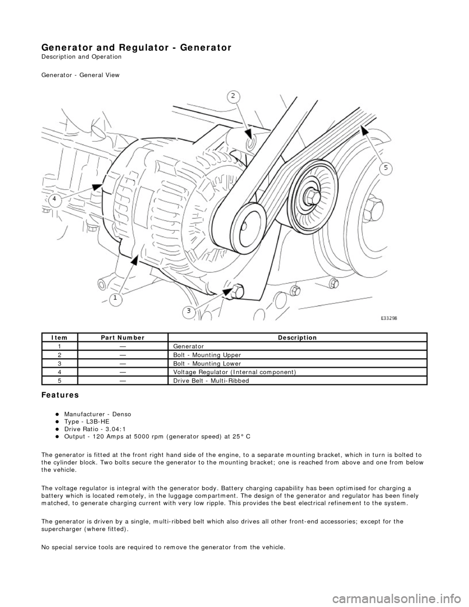
Generator - General View
Features
Manufacturer - Denso Type - L3B-HE Drive Ratio - 3.04:1 Output - 120 Amps at 5000 rpm (generator speed) at 25° C
The generator is fitted at the front right hand side of the engine, to a sepa rate mounting bracket, which in turn is bolted to
the cylinder block. Two bolts secure th e generator to the mounting bracket; one is reached from above and one from below
the vehicle.
The voltage regulator is integral with th e generator body. Battery charging capabi lity has been optimised for charging a
battery which is located remotely, in the luggage compartment. The design of the generator and regulator has been finely
matched, to generate charging current with very low ripple. This provides the best electrical refinement to the system.
The generator is driven by a single, multi-ribbed belt which also drives all other front-e nd accessories; except for the
supercharger (where fitted).
No special service tools are required to remove the generator from the vehicle.
ItemPart NumberDescription
1—Generator
2—Bolt - Mounting Upper
3—Bolt - Mounting Lower
4—Voltage Regulator (Internal component)
5—Drive Belt - Multi-Ribbed
Page 1904 of 2490
Audio Unit - Audio System
Description and Operation
The choice of two entertainment system s is available; base or premium.
The base system comprises a radio cassette player with in tegral message display and "Phone Ready" controls for an
accessory telephone; door speakers and tweeters.
The premium system has the following additional components: power amplifier, CD autochanger, sub-woofer and 'A' post
tweeters fitted instead of front door tweeters.
Both systems can be operated remotely by use of switches loca ted on the steering wheel and have an electrically operated
aerial.
Telephone controls incorporated in the ra dio cassette unit facilitate inclusion of the GSM hands free telephone system
available as optional equipment.
After diagnostic or repair operations, refer to the Sound System Handbook for setting-up procedures and operation.
Page 1962 of 2490
Interior Lighting - Interior Lighting
Description and Operation
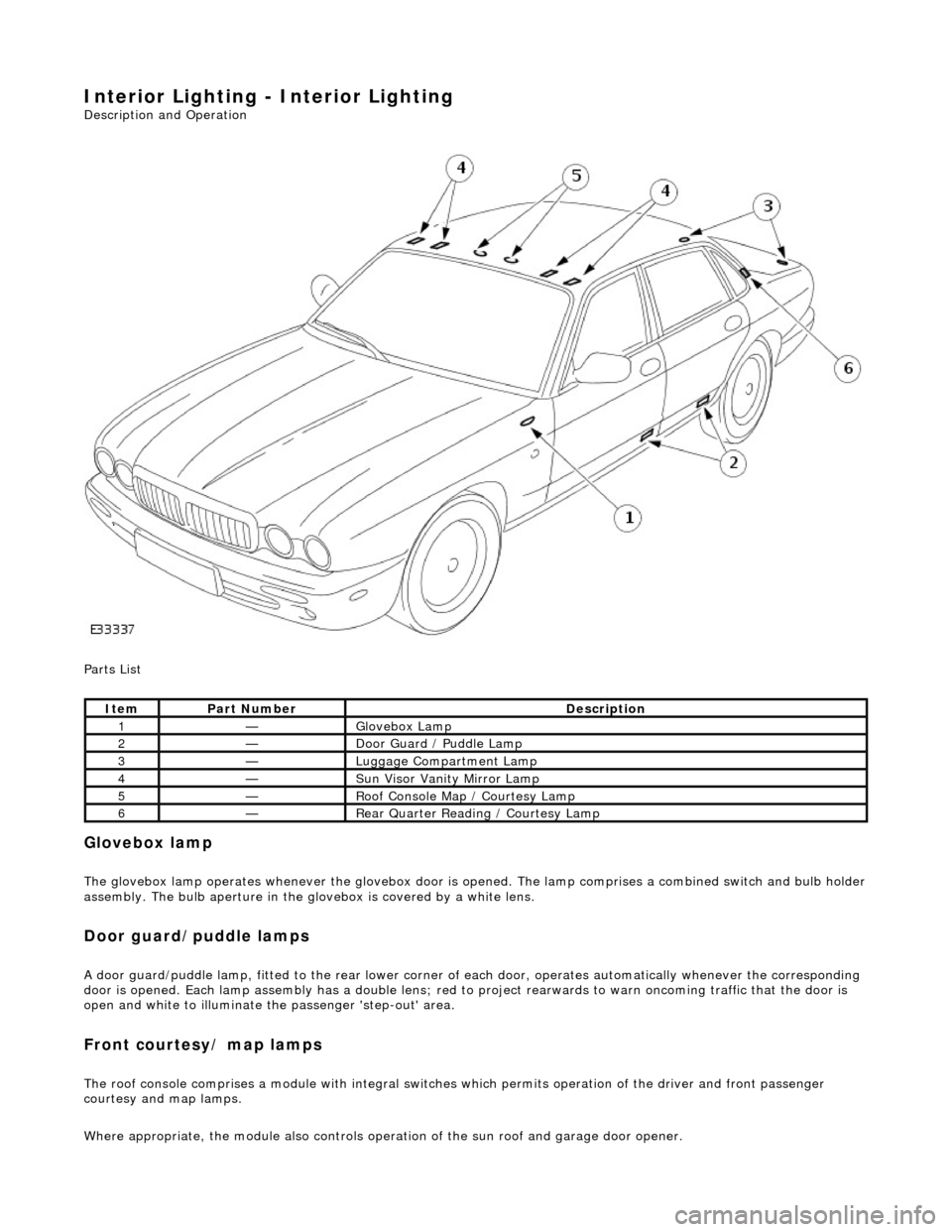
Parts List
Glovebox lamp
The glovebox lamp operates whenever the glovebox door is opened. The lamp comprises a combined switch and bulb holder assembly. The bulb aperture in the glovebox is covered by a white lens.
Door guard/puddle lamps
A door guard/puddle lamp, fitted to the rear lower corner of each door, operates automatically whenever the corresponding
door is opened. Each lamp assembly has a double lens; red to project rearwards to warn oncoming traffic that the door is
open and white to illuminate the passenger 'step-out' area.
Front courtesy/ map lamps
The roof console comprises a module with integral switches which permits operation of the dr iver and front passenger
courtesy and map lamps.
Where appropriate, the module also controls operation of the su n roof and garage door opener.
ItemPart NumberDescription
1—Glovebox Lamp
2—Door Guard / Puddle Lamp
3—Luggage Compartment Lamp
4—Sun Visor Vanity Mirror Lamp
5—Roof Console Map / Courtesy Lamp
6—Rear Quarter Reading / Courtesy Lamp
Page 1963 of 2490
Rear courtesy/ reading lamps
Each rear quarter of the passenger compartment is fitted with combined lighting units comprising; a rear courtesy lamp and
reading lamp. The courtesy lamps operate automatically whenever a rear door is opened; the reading lamps function when
the integral switches are operated by occupants of the vehicle.
Trunk lamps
The trunk trim panel is fitted with lamps which operate auto matically whenever the trunk lid is opened; the switch is
incorporated within the latch mechanism.
Vanity mirror lamps
The vanity mirror lamps, two on each sun visor, operate auto matically when the mirror flap is opened, provided the sun
visor spindle is engage d in the stowage clip.
Operation
The BPM provides an enable signal for the glovebox, vanity mirror, trunk lid and map lamps. Actuation of the relevant
switch provides an earth path to the lamp.
The rear passenger reading lamps receive a supply di rect from fuse F10 in the RH heelboard fuse-box.
The front and rear courtesy lamps have separa te fade functions controlled by the BPM.
The door hazard / puddle lamps are controll ed locally by the relevant Door Module.
Fault analysis must be undertaken using the PDU, refer to Diagnosis and Testing.
Refer to the relevant Electrical Guid e for details of circuit operation.
Page 1976 of 2490
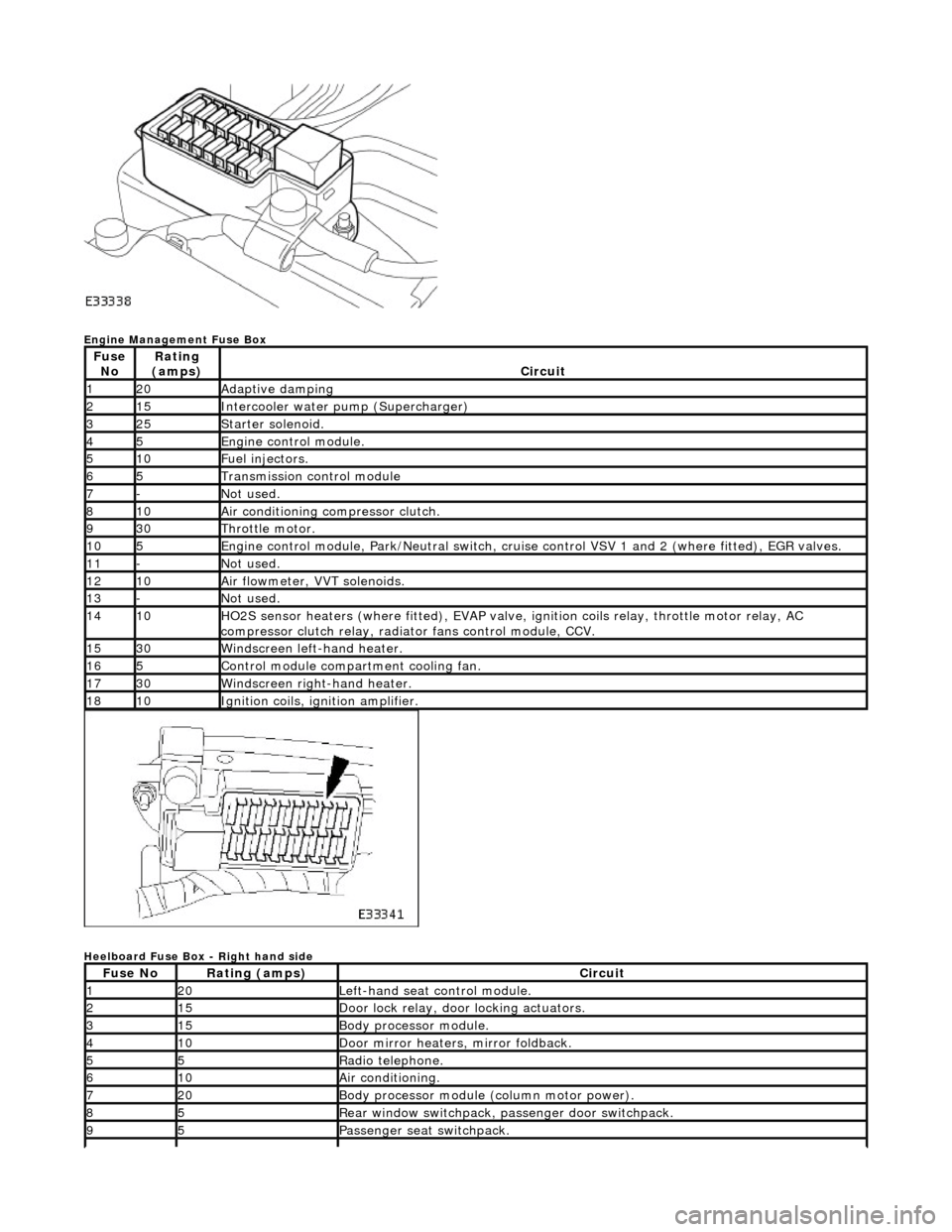
Engine Management Fuse Box
Heelboard Fuse Box - Right hand side
Fuse NoRating
(amps)Circuit
120Adaptive damping
215Intercooler water pump (Supercharger)
325Starter solenoid.
45Engine control module.
510Fuel injectors.
65Transmission control module
7-Not used.
810Air conditioning compressor clutch.
930Throttle motor.
105Engine control module, Park/Neutr al switch, cruise control VSV 1 and 2 (where fitted), EGR valves.
11-Not used.
1210Air flowmeter, VVT solenoids.
13-Not used.
1410HO2S sensor heaters (where fitted ), EVAP valve, ignition coils relay, throttle motor relay, AC
compressor clutch relay, radi ator fans control module, CCV.
1530Windscreen left-hand heater.
165Control module compartment cooling fan.
1730Windscreen right-hand heater.
1810Ignition coils, ignition amplifier.
Fuse NoRating (amps)Circuit
120Left-hand seat control module.
215Door lock relay, door locking actuators.
315Body processor module.
410Door mirror heaters, mirror foldback.
55Radio telephone.
610Air conditioning.
720Body processor module (column motor power).
85Rear window switchpack, passenger door switchpack.
95Passenger seat switchpack.
Page 2009 of 2490
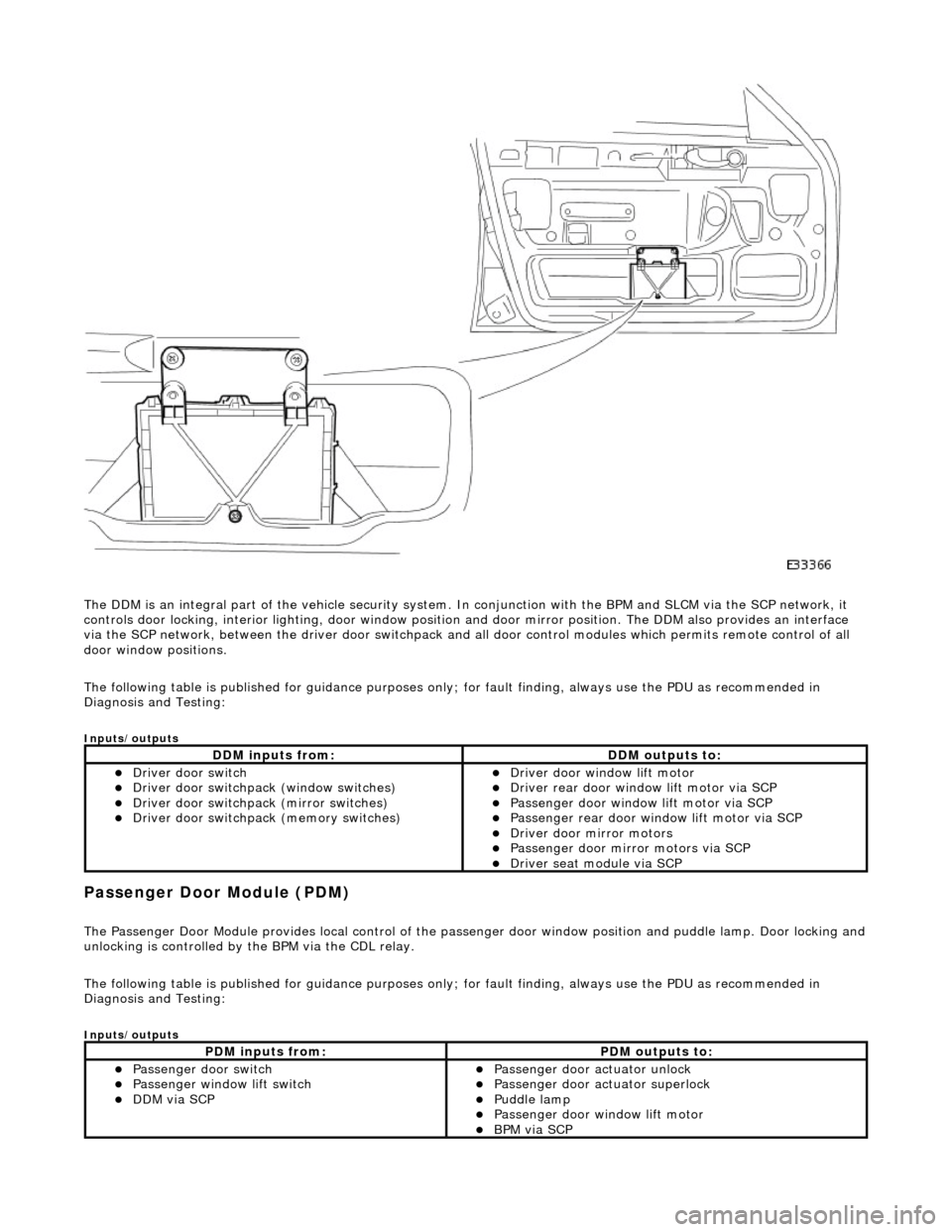
The DDM is an integral part of the vehi cle security system. In conjunction with the BPM and SLCM via the SCP network, it
controls door locking, interior lighting, door window position and door mirror position. The DDM also provides an interface
via the SCP network, between the driver door switchpack and all door control modules which permits remote control of all
door window positions.
The following table is published for guidance purp oses only; for fault finding, always use the PDU as recommended in
Diagnosis and Testing:
Inputs/outputs
Passenger Door Module (PDM)
The Passenger Door Module provides local control of the pass enger door window position and puddle lamp. Door locking and unlocking is controlled by the BPM via the CDL relay.
The following table is published for guidance purp oses only; for fault finding, always use the PDU as recommended in
Diagnosis and Testing:
Inputs/outputs
DDM inputs from:DDM outputs to:
Driver door switch Driver door switchpack (window switches) Driver door switchpack (mirror switches) Driver door switchpack (memory switches)
Driver door window lift motor Driver rear door window lift motor via SCP Passenger door window lift motor via SCP Passenger rear door window lift motor via SCP Driver door mirror motors Passenger door mirror motors via SCP Driver seat module via SCP
PDM inputs from:PDM outputs to:
Passenger door switch Passenger window lift switch DDM via SCP
Passenger door actuator unlock Passenger door actuator superlock Puddle lamp Passenger door window lift motor BPM via SCP
Page 2011 of 2490
The Roof Console Switch Module comprises integral switches which control the following:
Driver and passenger map lights
Main courtesy light
Garage door opener (where applicable)
The following table is published for guidance purp oses only; for fault finding, always use the PDU as recommended in
Diagnosis and Testing:
Inputs/outputs
Center Console Switch Module (CCSM)
RCSM inputs from:RCSM outputs to:
Illumination enable (BPM) Interior light fade 1 (BPM) BPM (master illumination light switch)