Page 1894 of 2490

Generator and Regulator - Generator4.0L SC V8 - AJ26
Removal and Installation
Removal
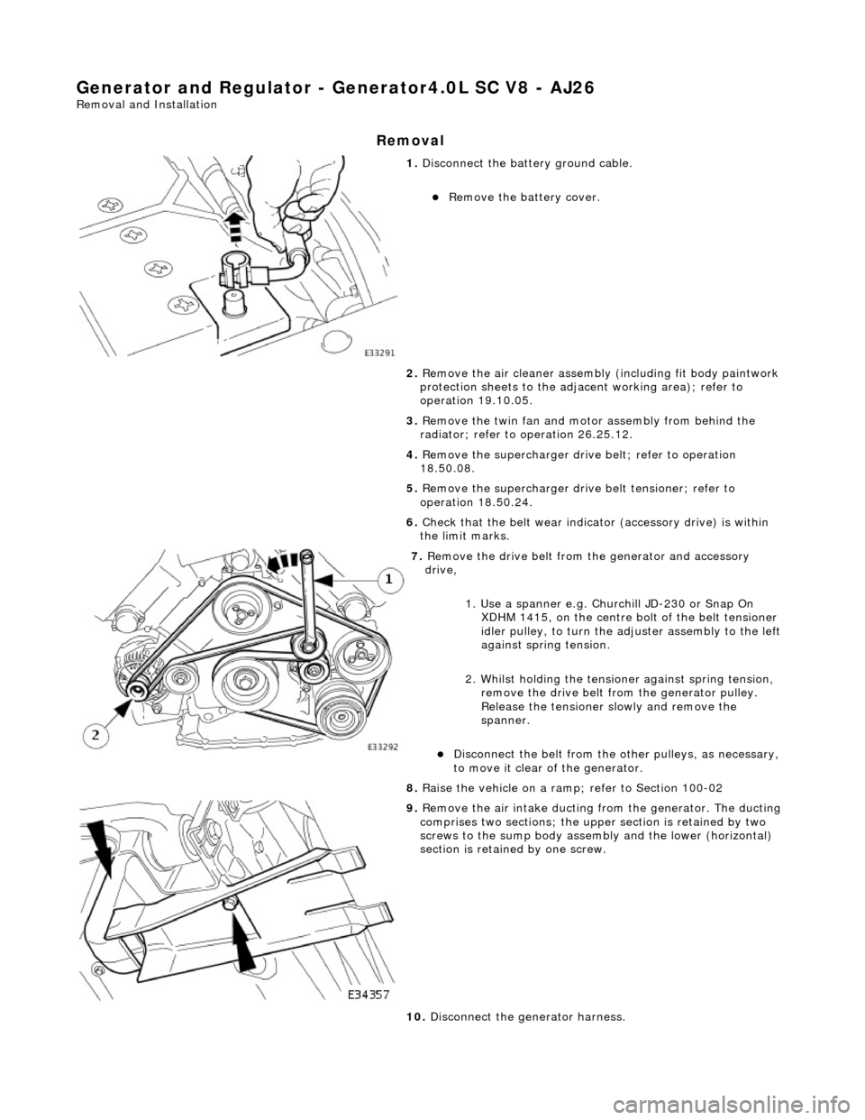
1. Disconnect the batt ery ground cable.
Remove the battery cover.
2. Remove the air cleaner assembly (including fit body paintwork
protection sheets to the adja cent working area); refer to
operation 19.10.05.
3. Remove the twin fan and moto r assembly from behind the
radiator; refer to operation 26.25.12.
4. Remove the supercharger drive belt; refer to operation
18.50.08.
5. Remove the supercharger driv e belt tensioner; refer to
operation 18.50.24.
6. Check that the belt wear indica tor (accessory drive) is within
the limit marks.
7. Remove the drive belt from the generator and accessory
drive,
1. Use a spanner e.g. Churchill JD-230 or Snap On XDHM 1415, on the centre bo lt of the belt tensioner
idler pulley, to turn the adju ster assembly to the left
against spring tension.
2. Whilst holding the tensioner against spring tension, remove the drive belt from the generator pulley.
Release the tensioner sl owly and remove the
spanner.
Disconnect the belt from the ot her pulleys, as necessary,
to move it clear of the generator.
8. Raise the vehicle on a ramp; refer to Section 100-02
9. Remove the air intake ducting fr om the generator. The ducting
comprises two sections; the upper section is retained by two
screws to the sump body assembly and the lower (horizontal)
section is retained by one screw.
10. Disconnect the generator harness.
Page 1895 of 2490
1. Disconnect the harness multi-plug.
2. Remove the protective boot from the positive
terminal, remove the termin al nut and disconnect the
cable from the terminal.
11. Remove the lower mounting bolt and reposition the harness
mounting bracket.
12. From above the vehicle, reposi tion the supercharger water
pump for access.
1. Reposition the pump harness multiplug from the
retaining bracket.
2. Remove the two nuts which secure the U-bracket around the pump.
3. Remove the U-bracket from the pump.
4. Reposition the pump to al low access for removing the
generator.
13. Remove the upper securing bolt and withdraw the generator
from the mounting bracket.
14. Carefully, manoeuvre the ge nerator forward towards the
radiator.
Page 1896 of 2490
Installation
15. Change the position of the ge nerator and remove it upwards
between the engine and the radiator.
16. Move the spacing bush rearward s slightly in the generator
mounting bracket, to ease fitting the new generator.
1. Position a suitable length bolt through the bush, fit a
tubular spacer or socket spanner, fit a nut and
tighten the assembly to move the bush slightly.
Remove the nut, bolt and spacer.
1. Fit the generator to the engine.
1. From above, position th e generator and fit the upper
mounting bolt and nut, but do not fully tighten.
2. Fit the generator lower mounting.
1. From below, reposition an d align the harness clip to
the generator lower mounting.
Page 1933 of 2490
Exterior Lighting - Headlamp Assembly
Removal and Installation
Removal
1. Remove radiator grill. Refer to 76.55.03.
2. Remove radiator grill surro und. Refer to 76.55.15.
3. Remove headlamp trim panel. Refer to 76.11.23.
4. Disconnect headlamp levelling actuator if fitted.
5. Disconnect headlamp assembly harness connector.
6. Remove headlamp assembly to body lower nuts.
7. Remove headlamp to body upper nuts.
Page 1935 of 2490
5. Align headlamp beams.
6. Install headlamp trim panel. Refer to 76.11.23.
7. Install radiator grill surround. Refer to 76.55.15.
8. Install radiator gril l. Refer to 76.55.03.
Page 1975 of 2490

Location of J1962 socket
The J1962 socket is located at the driver side inboard footwell.
Fuse Box Details
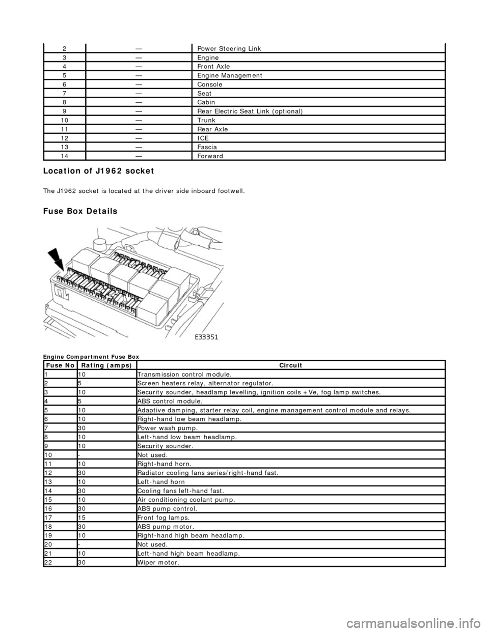
Engine Compartment Fuse Box
2—Power Steering Link
3—Engine
4—Front Axle
5—Engine Management
6—Console
7—Seat
8—Cabin
9—Rear Electric Seat Link (optional)
10—Trunk
11—Rear Axle
12—ICE
13—Fascia
14—Forward
Fuse NoRating (amps)Circuit
110Transmission control module.
25Screen heaters relay, alternator regulator.
310Security sounder, headlamp levelling, ignition coils +Ve, fog lamp switches.
45ABS control module.
510Adaptive damping, starter relay coil, engine management control module and relays.
610Right-hand low beam headlamp.
730Power wash pump.
810Left-hand low beam headlamp.
910Security sounder.
10-Not used.
1110Right-hand horn.
1230Radiator cooling fans series/right-hand fast.
1310Left-hand horn
1430Cooling fans left-hand fast.
1510Air conditioning coolant pump.
1630ABS pump control.
1715Front fog lamps.
1830ABS pump motor.
1910Right-hand high beam headlamp.
20-Not used.
2110Left-hand high beam headlamp.
2230Wiper motor.
Page 2027 of 2490
Front End Body Panels - Front End Body Panels
Description and Operation
The front body structure is de signed to satisfy bumper impact requiremen ts. The front bumper assembly forms a major
front structure component and is fully desc ribed in Section 501-19. The front fenders which are bolted to the front valances,
are fully described in the Body and Paint Repair manual.
Left and right hand false bulkheads together with insulation covers, installed between the engine compartment and the BIW
front bulkhead, provide optimum insulation against noise and heat intrusion. Two plenum braces bolted between the BIW
upper toeboard and the plenum, increa se bodyshell structural integrity.
The plastic radiator grill and vane block achieve weight reductions over steel components and provide high resistance to
front end corrosion.
Page 2031 of 2490
Front End Body Panels - Radiator Grille Opening Panel
Removal and Installation
Removal
Installation
1.
Open hood and fit fender covers.
2. Slacken and remove the ten cl osing panel securing bolts.
3. Position closing panel for access and disconnect hood switch
harness multiplug.
4. Remove closing panel from vehicle.
5. Remove and discard the two rubbe r grommets locating top of
radiator.
1. Fit and secure hood switch to closing panel.
2. Fit new rubber grommets to closing panel.
3. Position closing panel for access and connect hood harness
multiplug.
4. Fully seat closing panel and fit and tighten securing bolts.
5. Close hood and remove fender covers.