1998 JAGUAR X308 Radiator
[x] Cancel search: RadiatorPage 1127 of 2490
I
nstallation
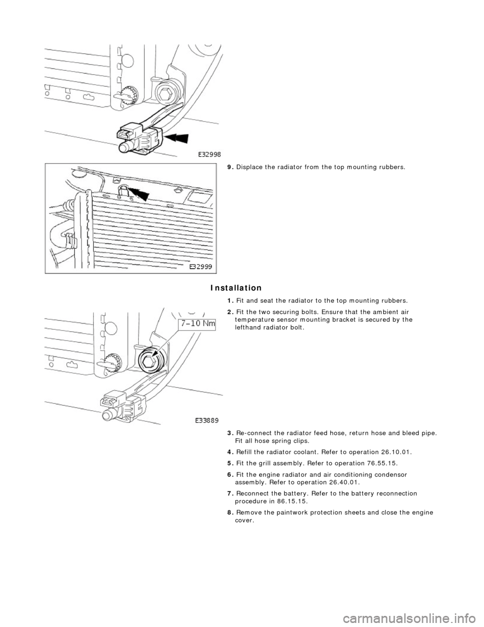
9.
Di
splace the radiator from
the top mounting rubbers.
1. Fit and seat the radiator to the top mounting rubbers.
2. F
it the two securing bolts.
Ensure that the ambient air
temperature sensor mounting bracket is secured by the
lefthand radiator bolt.
3. Re-connect the radiator feed ho se, return hose and bleed pipe.
Fit all hose spring clips.
4. Refill the radiator coolant. Refer to operation 26.10.01.
5. Fit the grill assembly. Refer to operation 76.55.15.
6. Fit the engine radiator and air conditioning condensor
assembly. Refer to operation 26.40.01.
7. Reconnect the battery. Refer to the battery reconnection
procedure in 86.15.15.
8. Remove the paintwork protection sheets and close the engine
cover.
Page 1128 of 2490
Intake Air Distribution and Filtering - Supercharger
Remo
val and Installation
Remov
a
l
Installation
1. Disc onne
ct battery ground cable (IMPORTANT, see SRO
86.15.19 for further information).
2. Drain radiator coolant; refer to 26.10.01.
3. Remove air cleaner cover / intake assembly; refer to 19.10.30.
4. Remove throttle body; refer to 19.70.04.
5. Remove exhaust gas re-circulation valve (EGR) if installed;
refer to 17.45.01.
6. Remove throttle intake elbo w; refer to (SC) 19.70.28.
7. Remove supercharger outlet duct; refer to 18.50.16.
8. Remove coolant outlet pipe; refe r to operation (SC) 26.31.08.
9. Remove supercharger drive belt; refer to 18.50.08.
10. Disconnect remaining coolant hoses from charge air coolers.
Position pipes to facilitate removal
of supercharger.
Inst
al
l suitable blanking plugs.
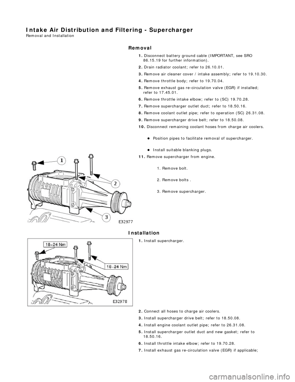
11 .
R
emove supercharger from engine.
1. Remove bolt.
2. Remove bolts .
3. Remove supercharger.
1. Inst al
l supercharger.
2. Connect all hoses to charge air coolers.
3. Install supercharger driv e belt; refer to 18.50.08.
4. Install engine coolant outlet pipe; refer to 26.31.08.
5. Install supercharger outlet du ct and new gasket; refer to
18.50.16.
6. Install throttle intake elbow; refer to 19.70.28.
7. Install exhaust gas re-circulation valve (EGR) if applicable;
Page 1130 of 2490
Intake Air Distribution and Filtering - Supercharger Outlet Pipe
Remo
val and Installation
Remov
a
l
1.
Re
move air cleaner cover / intake
assembly; refer to 19.10.30.
2. Drain radiator coolant; refer to operation (SC) 26.10.01.
3. Disc
onnect coolant hoses and vacuum pipe from supercharger
outlet duct.
Pl a
ce absorbent rags under
the two coolant hoses which
are connected to the outlet duct.
1. Remove vacuum pipe.
2. Disconnect hoses.
Plu g
hoses and outlet duct stub pipes to prevent spillage.
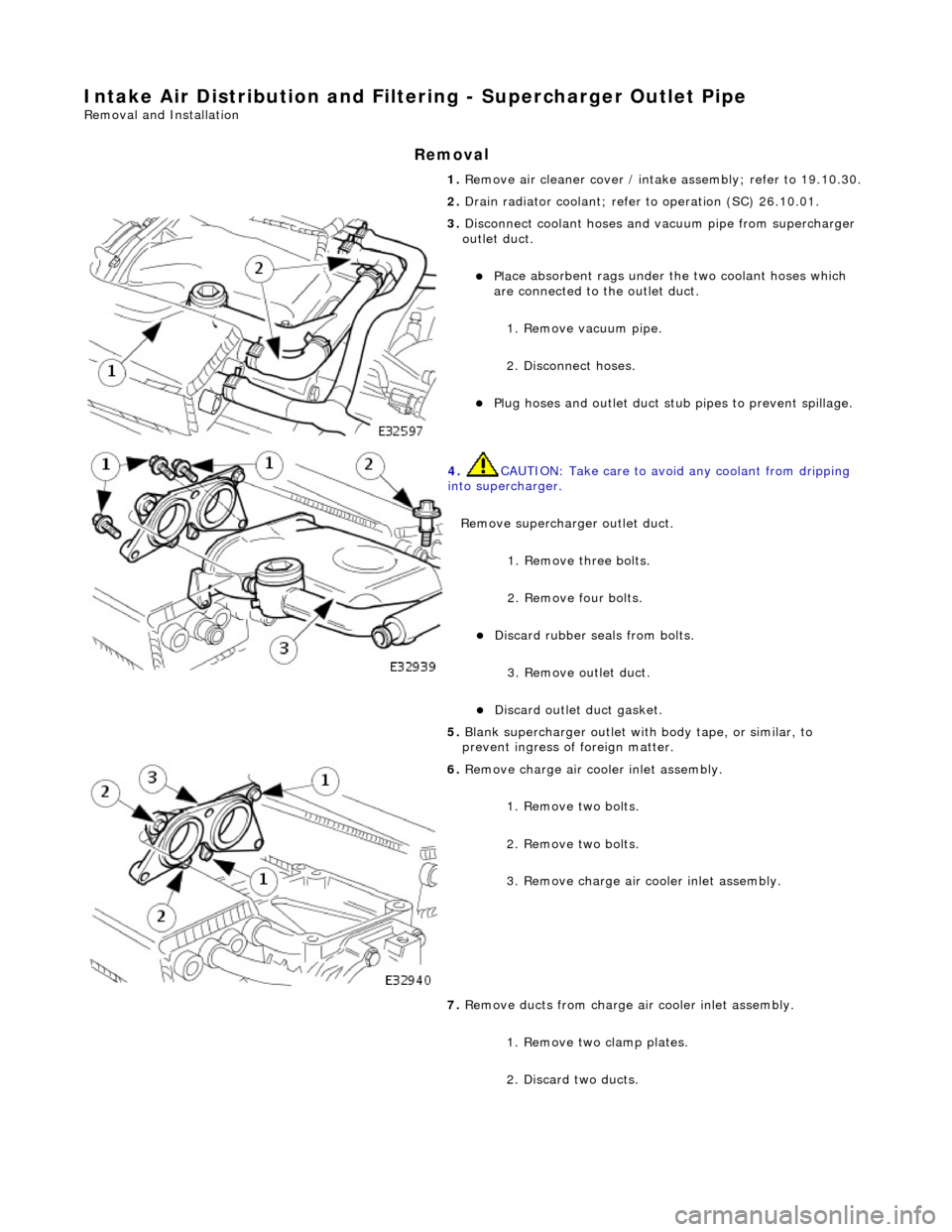
4. CAUTIO
N: Take care to avoi
d any coolant from dripping
into supercharger.
Remove supercharger outlet duct. 1. Remove three bolts.
2. Remove four bolts.
Di
scard rubber seals from bolts.
3. Remove outlet duct.
Discard ou
tlet duct gasket.
5.
Bla
nk supercharger outlet with
body tape, or similar, to
prevent ingress of foreign matter.
6. Remove charge air c oo
ler inlet assembly.
1. Remove two bolts.
2. Remove two bolts.
3. Remove charge air cooler inlet assembly.
7. Remove ducts from charge air cooler inlet assembly.
1. Remove two clamp plates.
2. Discard two ducts.
Page 1206 of 2490
or sho
rt circuit to B+ voltage
Ignition modul
e
2 ground circuit
fault
Ignition coil relay fai
lure
Ignition coil
open/short
circuit
Ignition modul
e
2 failure
P1474Int
e
rcooler coolant pump relay
malfunction
Intercooler pump relay failure
Intercooler pump relay
to ECM
drive circuit fault
Intercooler pump relay coi
l ground
circuit fault
ECM power supply f
ault
F
or i
ntercooler pump relay circuit
tests,GO to Pinpoint Test Z.
.
P1475Ra
diator fans slow
(series) circuit
malfunction
R a
diator fan control relay module
to ECM 'series' drive circuit (relay
pin 9) fault
Relay coil ignition power supply
o p
en circuit
ECM ground circuit fault (relay coil
drive)
ECT se ns
or circuit malfunction
(refer to P0116)
F o
r radiator fan seri
es circuit tests,GO
to Pinpoint Test AA.
P1476Ra
diator fans fast (parallel) circuit
malfunction
R a
diator fan control relay module
to ECM 'parallel' drive circuit (relay
pin 7) fault
Relay coil ignition power supply
o p
en circuit
ECM ground circuit faul
t (relay coil
drive)
ECT sens
or circuit malfunction
(refer to P0116)
F or radi
ator fan parallel circuit
tests,GO to Pinpoint Test AB.
.
P1516Gear change PARK
/NEUTRAL
driving malfunction
Transmission range (T
R) sensor to
ECM circuit open circuit or high
resistance
TR sensor f
ailure
D-
4
switch to TCM circuit open
circuit or high resistance
D-4 swi
tch fault
For
PARK/NEUTRAL tests,GO to
Pinpoint Test AC.
.
P1517Engine PA
RK/NEUTRAL
cranking
malfunction
Transmissi on range (T
R) sensor to
ECM circuit open circuit or high
resistance
TR sensor f
ailure
Fo
r
PARK/NEUTRAL tests,GO to
Pinpoint Test AC.
.
P1571Brake swit
ch malfunction
Brake sw
it
ch to ECM circuit open
circuit, short circ uit to ground, high
resistance
Brake sw it
ch ignition switched
ground circuit open circuit
Brake sw it
ch failure
Brake ca
ncel
switch to ECM circuit
open circuit, short circuit to
ground, high resistance
Brake ca nce
l switch to cruise
(speed) control switch circuit open
circuit, short circ uit to ground, high
resistance
Brake cance
l switch ignition
switched power supply open circuit
Brake ca nce
l switch failure
Cru
i
se (speed) control switch
failure
For cru i
se (speed) control circuit tests,
REF
E
R to Section 310
-03
Sp
eed
Control.
P1606Engine
m
anagement system
(EMS) control relay malfunction
ECM co ntrol rel
ay failure
ECM c
o
ntrol relay to ECM circuit
fault
ECM co ntrol rel
ay coil power supply
open circuit
ECM ground circuit faul t (relay coil
drive)
F or ECM
relay circuit tests,GO to
Pinpoint Test AD.
.
P1609EC
M microprocessor-to-
microprocessor communication
ECM failu r
e
Contact deal
er techni
cal support for
advice on possible ECM failure.
Page 1229 of 2490
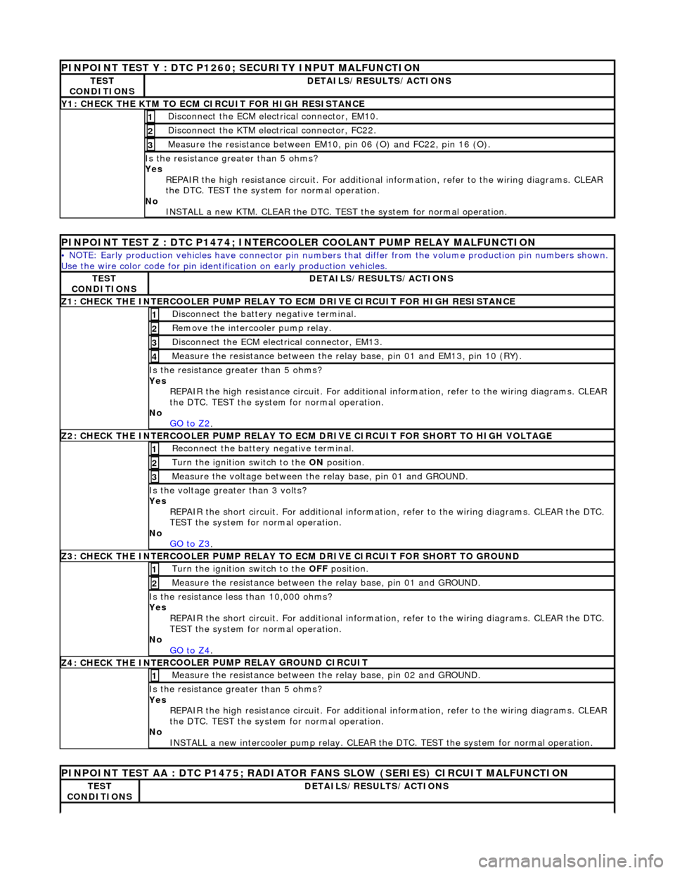
P
INPOINT TEST Y : DTC P1260; SECURITY INPUT MALFUNCTION
TE
ST
CONDITIONS
D
ETAILS/RESULTS/ACTIONS
Y1
: CHECK THE KTM TO ECM CIRCUIT FOR HIGH RESISTANCE
D
isconnect the ECM electrical connector, EM10.
1
D
isconnect the KTM electrical connector, FC22.
2
Me
asure the resistance between EM10, pin 06 (O) and FC22, pin 16 (O).
3
Is th
e resistance greater than 5 ohms?
Yes REPAIR the high resistance circui t. For additional information, refer to the wiring diagrams. CLEAR
the DTC. TEST the system for normal operation.
No INSTALL a new KTM. CLEAR the DTC. TEST the system for normal operation.
PINPO
INT TEST Z : DTC P1474; INTERCOOLER COOLANT PUMP RELAY MALFUNCTION
•
NOTE: Early production vehicl
es have connector pin numbers that differ fro m the volume production pin numbers shown.
Use the wire color code for pin identifi cation on early production vehicles.
TE
ST
CONDITIONS
D
ETAILS/RESULTS/ACTIONS
Z1
: CHECK THE INTERCOOLER PUMP RELAY TO ECM DRIVE CIRCUIT FOR HIGH RESISTANCE
Di
sconnect the battery negative terminal.
1
R
emove the intercooler pump relay.
2
D
isconnect the ECM electrical connector, EM13.
3
Meas
ure the resistance between the rela
y base, pin 01 and EM13, pin 10 (RY).
4
Is th
e resistance greater than 5 ohms?
Yes REPAIR the high resistance circui t. For additional information, refer to the wiring diagrams. CLEAR
the DTC. TEST the system for normal operation.
No GO to Z2
.
Z2
: CHECK THE INTERCOOLER PUMP RELAY TO EC
M DRIVE CIRCUIT FOR SHORT TO HIGH VOLTAGE
R
econnect the battery negative terminal.
1
Turn the ignition swi
tch to the ON
position.
2
Meas
ure the voltage between the
relay base, pin 01 and GROUND.
3
Is th
e voltage greater than 3 volts?
Yes REPAIR the short circuit. For addi tional information, refer to the wiring diagrams. CLEAR the DTC.
TEST the system for normal operation.
No GO to Z3
.
Z3
: CHECK THE INTERCOOLER PUMP RELAY TO
ECM DRIVE CIRCUIT FOR SHORT TO GROUND
Turn the ignition swi
tch to the OFF
position.
1
Meas
ure the resistance between th
e relay base, pin 01 and GROUND.
2
Is
the resistance less than 10,000 ohms?
Yes
REPAIR the short circuit. For addi tional information, refer to the wiring diagrams. CLEAR the DTC.
TEST the system for normal operation.
No GO to Z4
.
Z4: CHECK THE INTER
COOLER PUMP RELAY GROUND CIRCUIT
Meas
ure the resistance between th
e relay base, pin 02 and GROUND.
1
Is th
e resistance greater than 5 ohms?
Yes REPAIR the high resistance circui t. For additional information, refer to the wiring diagrams. CLEAR
the DTC. TEST the system for normal operation.
No INSTALL a new intercooler pump re lay. CLEAR the DTC. TEST the system for normal operation.
P
INPOINT TEST AA : DTC P1475; RADIATOR
FANS SLOW (SERIES) CIRCUIT MALFUNCTION
TE
ST
CONDITIONS
D
ETAILS/RESULTS/ACTIONS
Page 1230 of 2490
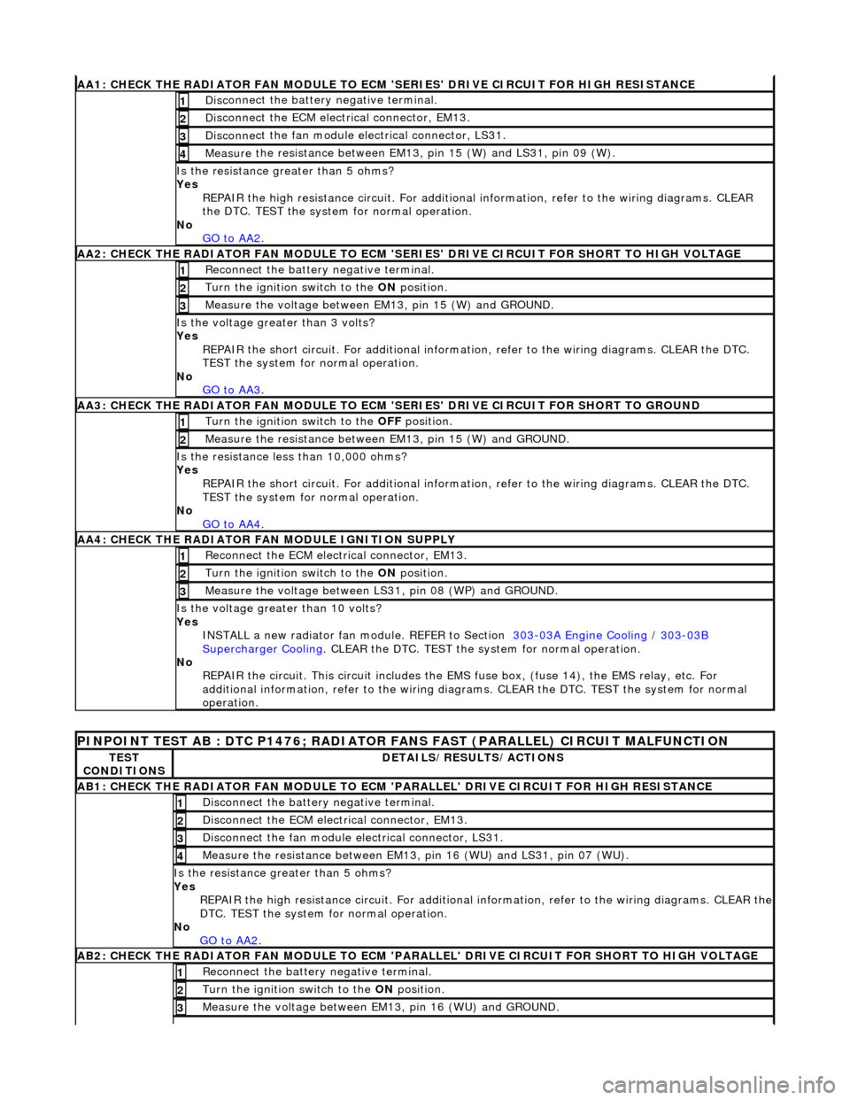
AA1: CHECK THE RA
DIATOR FAN MODULE TO ECM
'SERIES' DRIVE CIRCUIT FOR HIGH RESISTANCE
Disc
onnect the battery negative terminal.
1
D
i
sconnect the ECM electrical connector, EM13.
2
Disc
onne
ct the fan module electrical connector, LS31.
3
Meas
ure t
he resistance between EM13, pin 15 (W) and LS31, pin 09 (W).
4
Is th
e res
istance greater than 5 ohms?
Yes REPAIR the high resistance circui t. For additional information, refer to the wiring diagrams. CLEAR
the DTC. TEST the system for normal operation.
No GO to AA2
.
AA2: CHECK THE RA
DIATOR FAN MODULE TO ECM 'SER
IES' DRIVE CIRCUIT FOR SHORT TO HIGH VOLTAGE
Re
connect the battery negative terminal.
1
Turn the ignition swit
ch to the
ON position.
2
Measure t
he voltage between EM13, pin 15 (W) and GROUND.
3
Is the volt
age greater than 3 volts?
Yes REPAIR the short circuit. For addi tional information, refer to the wiring diagrams. CLEAR the DTC.
TEST the system for normal operation.
No GO to AA3
.
AA3: CHECK THE R A
DIATOR FAN MODULE TO ECM
'SERIES' DRIVE CIRCUIT FOR SHORT TO GROUND
Turn the ignition swit
ch to the
OFF position.
1
Meas ure t
he resistance between EM13, pin 15 (W) and GROUND.
2
Is
t
he resistance less than 10,000 ohms?
Yes
REPAIR the short circuit. For addi tional information, refer to the wiring diagrams. CLEAR the DTC.
TEST the system for normal operation.
No GO to AA4
.
AA4:
CHECK THE RADIATOR FAN MODULE IGNITION SUPPLY
Reconn
ect the ECM electrical connector, EM13.
1
Turn the ignition swit
ch to the
ON position.
2
Measure the voltage between LS 31,
pin 08 (WP) and GROUND.
3
Is the vol
t
age greater than 10 volts?
Yes INSTALL a new radiator fan module. REFER to Section 303
-03
A Engine Cooling
/
303-03B Supercharger Cooli
ng
. CLEA
R the DTC. TEST the sy stem f
or normal operation.
No REPAIR the circuit. This circui t includes the EMS fuse box, (f use 14), the EMS relay, etc. For
additional information, refer to the wiring diagrams. CLEAR the DT C. TEST the system for normal
operation.
PINPOINT TE ST
AB : DTC P1476; RADIATOR
FANS FAST (PARALLEL) CIRCUIT MALFUNCTION
TES
T
CONDITIONS
D E
TAILS/RESULTS/ACTIONS
AB1
:
CHECK THE RADIATOR FAN MODULE TO ECM
'PARALLEL' DRIVE CIRCUIT FOR HIGH RESISTANCE
Disc
onnect the battery negative terminal.
1
D
i
sconnect the ECM electrical connector, EM13.
2
Disc
onne
ct the fan module electrical connector, LS31.
3
Meas
ure t
he resistance between EM13, pin 16 (WU) and LS31, pin 07 (WU).
4
Is th
e res
istance greater than 5 ohms?
Yes REPAIR the high resistance circuit. For additional information, refer to the wiring diagrams. CLEAR the
DTC. TEST the system for normal operation.
No GO to AA2
.
AB2:
CHECK THE RADIATOR FAN MODULE TO ECM 'PARALLEL' DRIVE CIRCUIT FOR SHORT TO HIGH VOLTAGE
R
e
connect the battery negative terminal.
1
Turn the ignition swi
t
ch to the ON
position.
2
Measure t
he voltage between EM13, pin 16 (WU) and GROUND.
3
Page 1231 of 2490
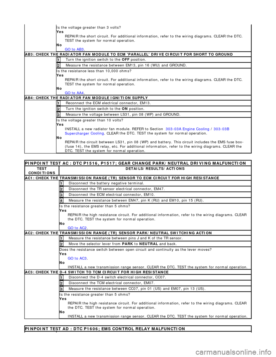
Is th
e voltage greater than 3 volts?
Yes REPAIR the short circuit. For addi tional information, refer to the wiring diagrams. CLEAR the DTC.
TEST the system for normal operation.
No GO to AB3
.
AB3
: CHECK THE RADIATOR FAN MODULE TO ECM
'PARALLEL' DRIVE CIRCUIT FOR SHORT TO GROUND
Turn the ignition swi
tch to the OFF
position.
1
Meas
ure the resistance between EM13, pin 16 (WU) and GROUND.
2
Is
the resistance less than 10,000 ohms?
Yes
REPAIR the short circuit. For addi tional information, refer to the wiring diagrams. CLEAR the DTC.
TEST the system for normal operation.
No GO to AA4
.
AB4
: CHECK THE RADIATOR FAN MODULE IGNITION SUPPLY
Re
connect the ECM electrical connector, EM13.
1
Turn the ignition swi
tch to the ON
position.
2
Measure the
voltage between LS
31, pin 08 (WP) and GROUND.
3
Is the vol
tage greater than 10 volts?
Yes INSTALL a new radiator fan module. REFER to Section 303
-0
3A Engine Cooling
/
30
3
-03
B
Supercharger
Cooling
. CLEA
R the DTC. TEST the sy
stem for normal operation.
No REPAIR the circuit between LS31, pin 08 (WP) and battery. This circuit includes the EMS fuse box-
(fuse 14), the EMS relay, etc. For additional information, refer to the wiring diagrams. CLEAR the
DTC. TEST the system for normal operation.
P
INPOINT TEST AC : DTC P1516, P1517; GEAR
CHANGE PARK/NEUTRAL DRIVING MALFUNCTION
TE
ST
CONDITIONS
D
ETAILS/RESULTS/ACTIONS
AC1: CH
ECK THE TRANSMISSION RANGE (TR) SE
NSOR TO ECM CIRCUIT FOR HIGH RESISTANCE
Di
sconnect the battery negative terminal.
1
Di
sconnect the TR sensor el
ectrical connector, EM47.
2
D
isconnect the ECM electrical connector, EM10.
3
Meas
ure the resistance between EM47, pin K (RU) and EM10, pin 15 (RU).
4
Is th
e resistance greater than 5 ohms?
Yes REPAIR the high resistance circui t. For additional information, refer to the wiring diagrams. CLEAR
the DTC. TEST the system for normal operation.
No GO to AC2
.
AC2: CH
ECK THE TRANSMISSION RANGE (TR)
SENSOR PARK/NEUTRAL SWITCHING ACTION
Meas
ure the resistance between pi
ns J and K of the TR sensor.
1
Mo
ve the selector lever from
PARK to NEUTRAL and back.
2
D
oes the resistance switch between open ci
rcuit and continuity as the lever moves?
Yes GO to AC3
.
No
INSTALL a new transmission range sensor. CLEAR th e DTC. TEST the system for normal operation.
AC3: CH
ECK THE D-4 SWITCH TO
TCM CIRCUIT FOR HIGH RESISTANCE
Di
sconnect the D-4 switch electrical connector, CC07.
1
Di
sconnect the TCM electrical connector, EM07.
2
Meas
ure the resistance between CC07,
pin 01 (US) and EM07, pin 13 (US).
3
Is th
e resistance greater than 5 ohms?
Yes REPAIR the high resistance circui t. For additional information, refer to the wiring diagrams. CLEAR
the DTC. TEST the system for normal operation.
No INSTALL a new transmission range sensor. CLEAR th e DTC. TEST the system for normal operation.
P
INPOINT TEST AD : DTC P1606;
EMS CONTROL RELAY MALFUNCTION
Page 1449 of 2490
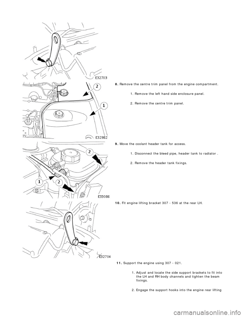
8. Remove the centre trim panel from the engine compartment.
1. Remove the left hand side enclosure panel.
2. Remove the centre trim panel.
9. Move the coolant header tank for access.
1. Disconnect the bleed pipe, header tank to radiator .
2. Remove the header tank fixings.
10. Fit engine lifting bracket 307 - 536 at the rear LH.
11. Support the engine using 307 - 021.
1. Adjust and locate the side support brackets to fit into
the LH and RH body channels and tighten the beam
fixings.
2. Engage the support hooks in to the engine rear lifting