1998 JAGUAR X308 belt
[x] Cancel search: beltPage 1887 of 2490
Generator and Regulator - Generator
Diagnosis and Testing
Refer to PDU User Guide
Refer to the PDU User Manual for detailed instructions on testing the charging circuit.
When diagnosing the charging ci rcuit, the PDU indicates only whether the generator is charging or not charging. The reason
for this is that the PDU cannot handle the potential full charging current and that the voltage control circuits are located
within the generator assembly, making th em inaccessible by the PDU directly.
It is possible that the battery has failed. In this case, the voltage output at the generator could be correct, but the voltage
at the battery terminals, and therefore the rest of the vehicl e system, will be adversely affected by the faulty battery.
The same result is given by the PDU if the battery is faulty (generator not faulty), wiring fault (damaged or severe corrosion
at the terminals) or if th e generator is at fault.
Inspection and Verification
The following manual tests help to pinpoint which component is at fault.
Testing the Battery Circuit
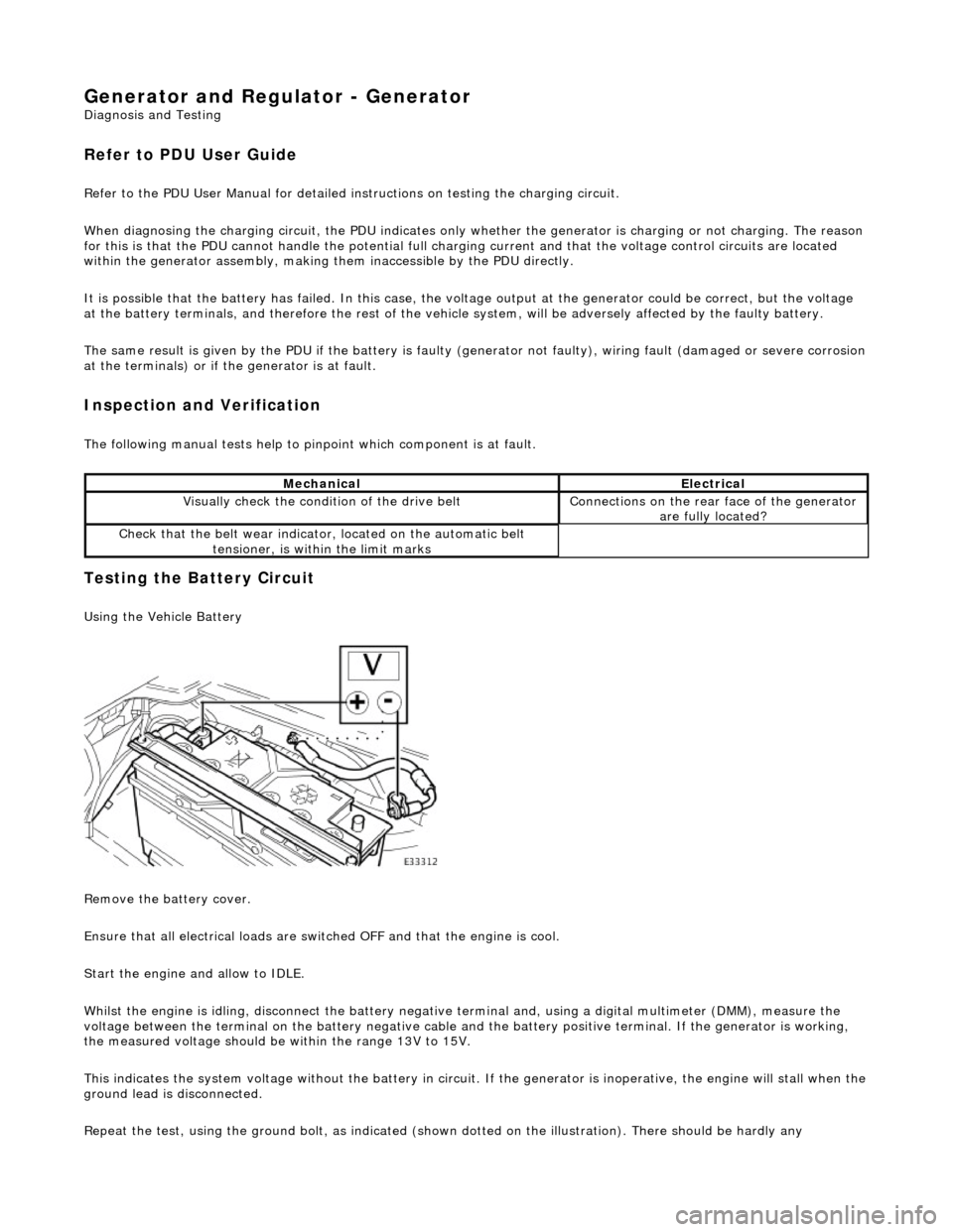
Using the Vehicle Battery
Remove the battery cover.
Ensure that all electrical loads are swit ched OFF and that the engine is cool.
Start the engine and allow to IDLE.
Whilst the engine is idling, disconnect the battery negative terminal and, using a digital multimeter (DMM), measure the
voltage between the terminal on the batter y negative cable and the battery positive terminal. If the generator is working,
the measured voltage should be within the range 13V to 15V.
This indicates the system voltage without the battery in circuit. If the generator is inoperative, the engine will stall when t he
ground lead is disconnected.
Repeat the test, using the ground bolt, as indicated (shown dotted on the illustration). There should be hardly any
MechanicalElectrical
Visually check the condition of the drive beltConnections on the rear face of the generator
are fully located?
Check that the belt we ar indicator, located on the automatic belt
tensioner, is within the limit marks
Page 1890 of 2490
Generator and Regulator - Generator4.0L NA V8 - AJ27/3.2L NA V8 - AJ26
Removal and Installation
Removal
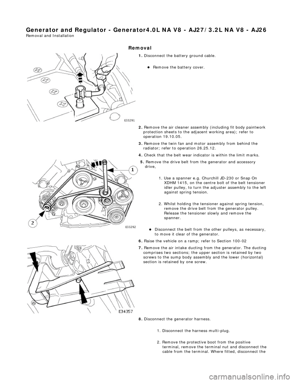
1. Disconnect the batt ery ground cable.
Remove the battery cover.
2. Remove the air cleaner assembly (including fit body paintwork
protection sheets to the adja cent working area); refer to
operation 19.10.05.
3. Remove the twin fan and moto r assembly from behind the
radiator; refer to operation 26.25.12.
4. Check that the belt wear indicator is within the limit marks.
5. Remove the drive belt from the generator and accessory
drive,
1. Use a spanner e.g. Churchill JD-230 or Snap On XDHM 1415, on the centre bo lt of the belt tensioner
idler pulley, to turn the adju ster assembly to the left
against spring tension.
2. Whilst holding the tensioner against spring tension, remove the drive belt from the generator pulley.
Release the tensioner sl owly and remove the
spanner.
Disconnect the belt from the ot her pulleys, as necessary,
to move it clear of the generator.
6. Raise the vehicle on a ramp; refer to Section 100-02
7. Remove the air intake ducting fr om the generator. The ducting
comprises two sections; the upper section is retained by two
screws to the sump body assembly and the lower (horizontal)
section is retained by one screw.
8. Disconnect the generator harness.
1. Disconnect the harness multi-plug.
2. Remove the protective boot from the positive
terminal, remove the termin al nut and disconnect the
cable from the terminal. Where fitted, disconnect the
Page 1893 of 2490
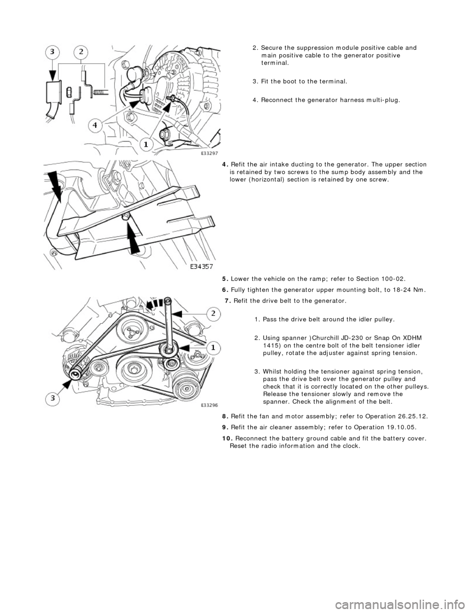
2. Secure the suppression module positive cable and
main positive cable to the generator positive
terminal.
3. Fit the boot to the terminal.
4. Reconnect the generator harness multi-plug.
4. Refit the air intake ducting to the generator. The upper section
is retained by two screws to the sump body assembly and the
lower (horizontal) section is retained by one screw.
5. Lower the vehicle on the ramp ; refer to Section 100-02.
6. Fully tighten the generator upper mounting bolt, to 18-24 Nm.
7. Refit the drive belt to the generator.
1. Pass the drive belt around the idler pulley.
2. Using spanner )Churchill JD-230 or Snap On XDHM 1415) on the centre bolt of the belt tensioner idler
pulley, rotate the adjuster against spring tension.
3. Whilst holding the tensioner against spring tension, pass the drive belt over the generator pulley and
check that it is correctly located on the other pulleys.
Release the tensioner slowly and remove the
spanner. Check the alignment of the belt.
8. Refit the fan and motor assembly ; refer to Operation 26.25.12.
9. Refit the air cleaner assembly; refer to Operation 19.10.05.
10. Reconnect the battery ground cable and fit the battery cover.
Reset the radio inform ation and the clock.
Page 1894 of 2490
Generator and Regulator - Generator4.0L SC V8 - AJ26
Removal and Installation
Removal
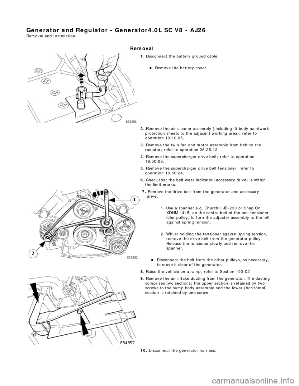
1. Disconnect the batt ery ground cable.
Remove the battery cover.
2. Remove the air cleaner assembly (including fit body paintwork
protection sheets to the adja cent working area); refer to
operation 19.10.05.
3. Remove the twin fan and moto r assembly from behind the
radiator; refer to operation 26.25.12.
4. Remove the supercharger drive belt; refer to operation
18.50.08.
5. Remove the supercharger driv e belt tensioner; refer to
operation 18.50.24.
6. Check that the belt wear indica tor (accessory drive) is within
the limit marks.
7. Remove the drive belt from the generator and accessory
drive,
1. Use a spanner e.g. Churchill JD-230 or Snap On XDHM 1415, on the centre bo lt of the belt tensioner
idler pulley, to turn the adju ster assembly to the left
against spring tension.
2. Whilst holding the tensioner against spring tension, remove the drive belt from the generator pulley.
Release the tensioner sl owly and remove the
spanner.
Disconnect the belt from the ot her pulleys, as necessary,
to move it clear of the generator.
8. Raise the vehicle on a ramp; refer to Section 100-02
9. Remove the air intake ducting fr om the generator. The ducting
comprises two sections; the upper section is retained by two
screws to the sump body assembly and the lower (horizontal)
section is retained by one screw.
10. Disconnect the generator harness.
Page 1897 of 2490
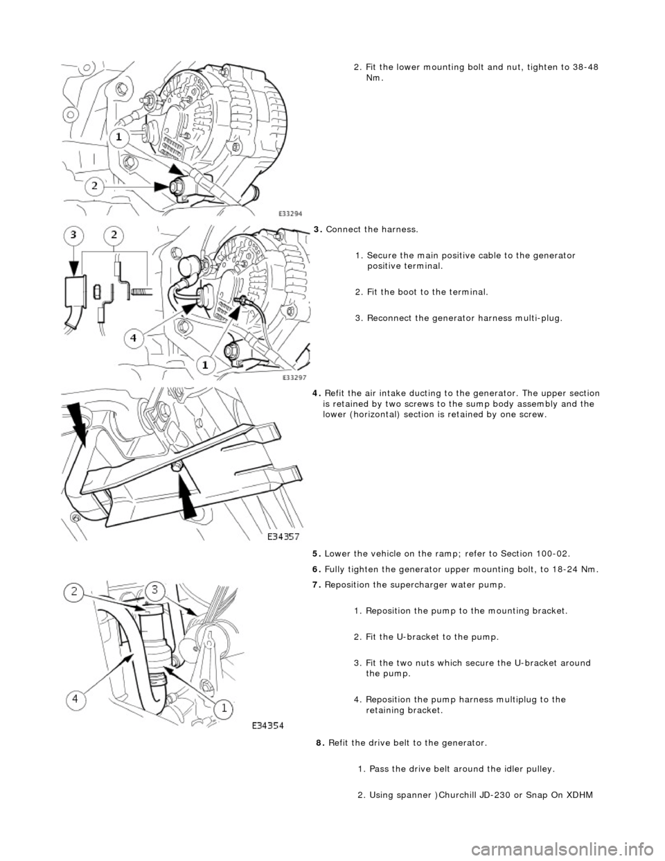
2. Fit the lower mounting bolt and nut, tighten to 38-48
Nm.
3. Connect the harness.
1. Secure the main positive cable to the generator positive terminal.
2. Fit the boot to the terminal.
3. Reconnect the generator harness multi-plug.
4. Refit the air intake ducting to the generator. The upper section
is retained by two screws to the sump body assembly and the
lower (horizontal) section is retained by one screw.
5. Lower the vehicle on the ramp ; refer to Section 100-02.
6. Fully tighten the generator upper mounting bolt, to 18-24 Nm.
7. Reposition the superc harger water pump.
1. Reposition the pump to the mounting bracket.
2. Fit the U-bracket to the pump.
3. Fit the two nuts which secure the U-bracket around the pump.
4. Reposition the pump harness multiplug to the retaining bracket.
8. Refit the drive belt to the generator.
1. Pass the drive belt around the idler pulley.
2. Using spanner )Churchill JD-230 or Snap On XDHM
Page 1898 of 2490
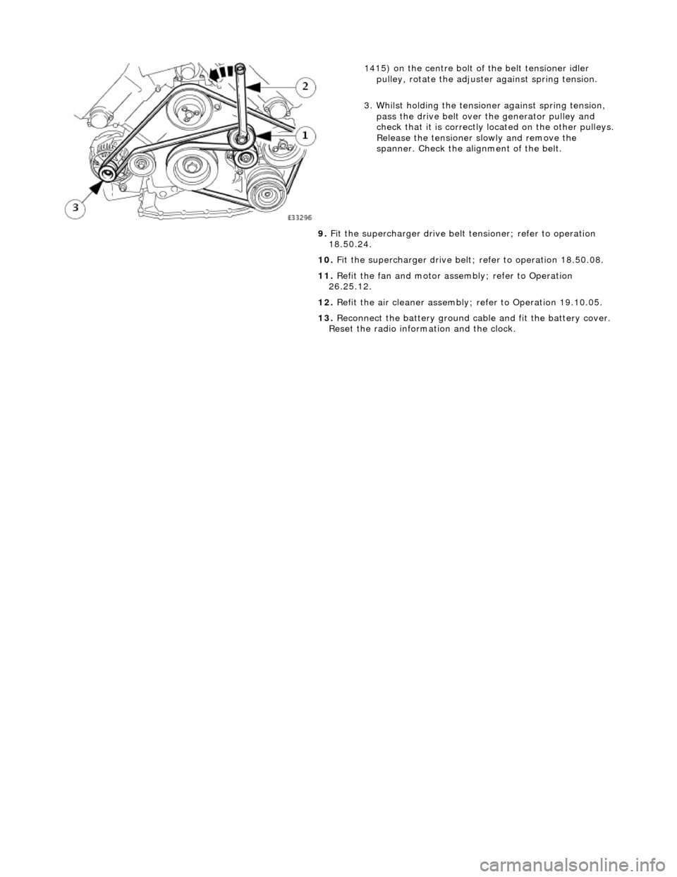
1415) on the centre bolt of the belt tensioner idler
pulley, rotate the adjuster against spring tension.
3. Whilst holding the tensioner against spring tension, pass the drive belt over the generator pulley and
check that it is correctly located on the other pulleys.
Release the tensioner slowly and remove the
spanner. Check the alignment of the belt.
9. Fit the supercharger drive belt tensioner; refer to operation
18.50.24.
10. Fit the supercharger drive belt ; refer to operation 18.50.08.
11. Refit the fan and motor asse mbly; refer to Operation
26.25.12.
12. Refit the air cleaner assembly; refer to Operation 19.10.05.
13. Reconnect the battery ground cable and fit the battery cover.
Reset the radio inform ation and the clock.
Page 2019 of 2490
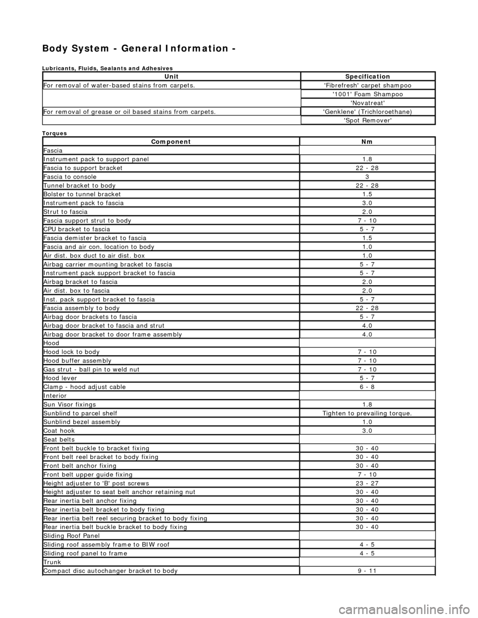
Body System - General Information -
Lubricants, Fluids, Sealants and Adhesives
Torques
UnitSpecification
For removal of water-based stains from carpets.'Fibrefresh' carpet shampoo
'1001' Foam Shampoo
'Novatreat'
For removal of grease or oil based stains from carpets.'Genklene' (Trichloroethane)
'Spot Remover'
ComponentNm
Fascia
Instrument pack to support panel1.8
Fascia to support bracket22 - 28
Fascia to console3
Tunnel bracket to body22 - 28
Bolster to tunnel bracket1.5
Instrument pack to fascia3.0
Strut to fascia2.0
Fascia support strut to body7 - 10
CPU bracket to fascia5 - 7
Fascia demister bracket to fascia1.5
Fascia and air con. location to body1.0
Air dist. box duct to air dist. box1.0
Airbag carrier mounting bracket to fascia5 - 7
Instrument pack suppo rt bracket to fascia5 - 7
Airbag bracket to fascia2.0
Air dist. box to fascia2.0
Inst. pack support bracket to fascia5 - 7
Fascia assembly to body22 - 28
Airbag door brackets to fascia5 - 7
Airbag door bracket to fascia and strut4.0
Airbag door bracket to door frame assembly4.0
Hood
Hood lock to body7 - 10
Hood buffer assembly7 - 10
Gas strut - ball pin to weld nut7 - 10
Hood lever5 - 7
Clamp - hood adjust cable6 - 8
Interior
Sun Visor fixings1.8
Sunblind to parcel shelfTighten to prevailing torque.
Sunblind bezel assembly1.0
Coat hook3.0
Seat belts
Front belt buckle to bracket fixing30 - 40
Front belt reel bracket to body fixing30 - 40
Front belt anchor fixing30 - 40
Front belt upper guide fixing7 - 10
Height adjuster to 'B' post screws23 - 27
Height adjuster to seat belt anchor retaining nut30 - 40
Rear inertia belt anchor fixing30 - 40
Rear inertia belt bracket to body fixing30 - 40
Rear inertia belt reel secu ring bracket to body fixing30 - 40
Rear inertia belt buckle bracket to body fixing30 - 40
Sliding Roof Panel
Sliding roof assembly frame to BIW roof4 - 5
Sliding roof panel to frame4 - 5
Trunk
Compact disc autochanger bracket to body9 - 11
Page 2022 of 2490
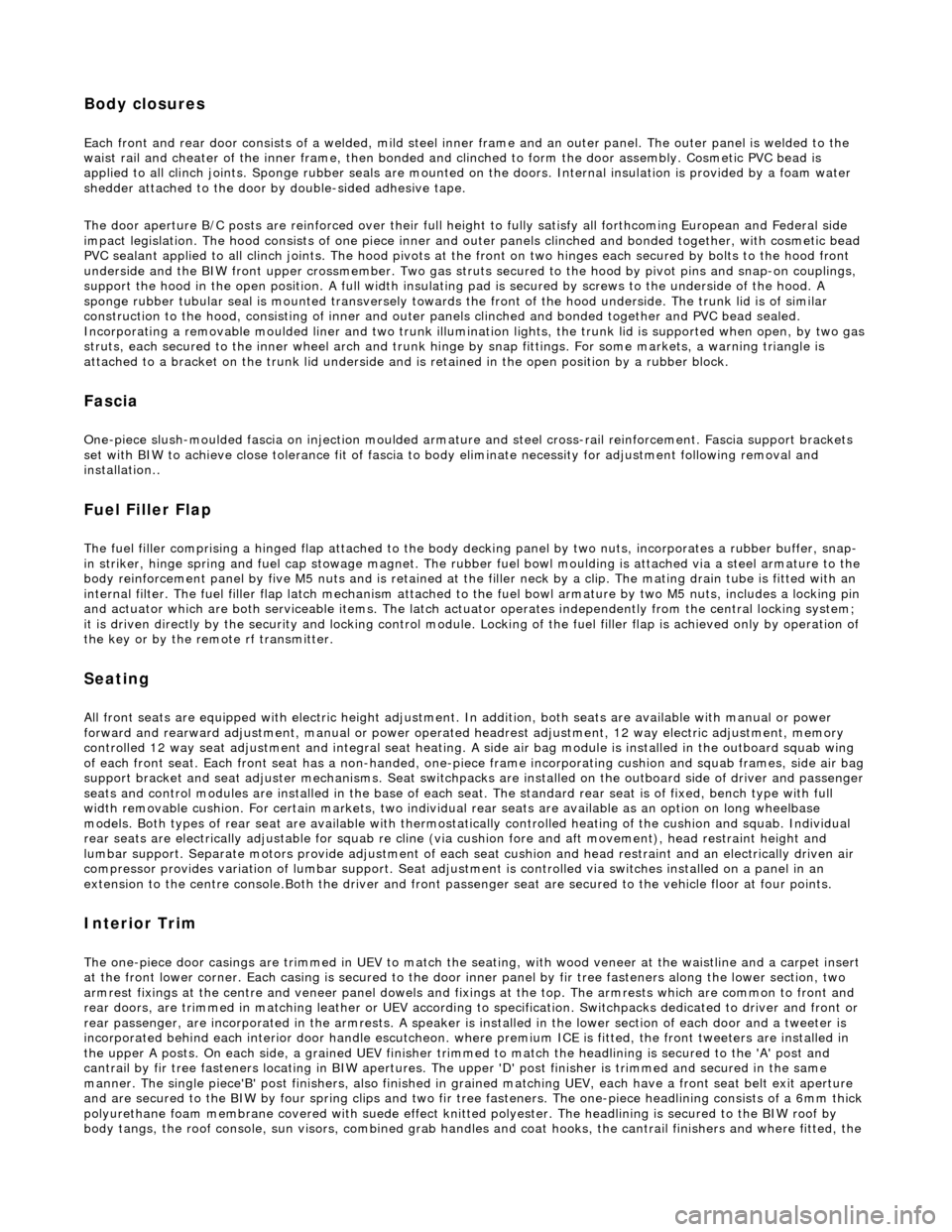
Body closures
Each front and rear door consists of a welded, mild steel inner frame and an outer panel. The outer panel is welded to the
waist rail and cheater of the inner frame, then bonded and clinched to fo rm the door assembly. Cosmetic PVC bead is
applied to all clinch joints. Sp onge rubber seals are mounted on the doors. Inte rnal insulation is provided by a foam water
shedder attached to the door by double-sided adhesive tape.
The door aperture B/C posts are reinforced over their full height to fully satisfy all forthcoming European and Federal side
impact legislation. The hood consists of one piece inner and outer panels clinched and bonded together, with cosmetic bead
PVC sealant applied to all clinch joints. Th e hood pivots at the front on two hinges each secured by bolts to the hood front
underside and the BIW front upper crossmem ber. Two gas struts secured to the hood by pivot pins and snap-on couplings,
support the hood in the open position. A full width insulating pad is secured by screws to the underside of the hood. A
sponge rubber tubular seal is mounted tran sversely towards the front of the hood underside. The trunk lid is of similar
construction to the hood, consisting of inner and outer pa nels clinched and bonded together and PVC bead sealed.
Incorporating a removable moulded liner and two trunk illuminati on lights, the trunk lid is supported when open, by two gas
struts, each secured to the inner wheel arch and trunk hinge by snap fittin gs. For some markets, a warning triangle is
attached to a bracket on the trunk lid underside and is retained in the open position by a rubber block.
Fascia
One-piece slush-moulded fascia on inject ion moulded armature and steel cross-rail reinforcement. Fascia support brackets
set with BIW to achieve close tolerance fit of fascia to bo dy eliminate necessity for adjustment following removal and
installation..
Fuel Filler Flap
The fuel filler comprising a hinged flap attached to the body decking panel by tw o nuts, incorporates a rubber buffer, snap-
in striker, hinge spring and fuel cap stowage magnet. The rubber fuel bowl moulding is attached via a steel armature to the
body reinforcement panel by five M5 nuts and is retained at the filler neck by a clip. The mating drain tube is fitted with an
internal filter. The fuel filler flap latch mechanism attached to the fuel bowl armatu re by two M5 nuts, includes a locking pin
and actuator which are both se rviceable items. The latch actuator operates independently from the central locking system;
it is driven directly by the se curity and locking control module. Locking of the fuel filler flap is achi eved only by operation of
the key or by the remote rf transmitter.
Seating
All front seats are equipped with electric height adjustment. In addition, both seats are available with manual or power
forward and rearward adjustment, manual or power operated headrest adjustment, 12 way electric adjustment, memory
controlled 12 way seat adjustment and integral seat heating. A side air bag module is installe d in the outboard squab wing
of each front seat. Each front seat has a non-handed, one-piece frame incorporatin g cushion and squab frames, side air bag
support bracket and seat adjuster mechanis ms. Seat switchpacks are installed on the outboard side of driver and passenger
seats and control modules are installed in the base of each seat . The standard rear seat is of fixed, bench type with full
width removable cushion. For certain mark ets, two individual rear seats are available as an option on long wheelbase
models. Both type s of rear seat are available with th ermostatically controlled heating of the cushion and sq uab. Individual
rear seats are electrically adjustable fo r squab re cline (via cushion fore and af t movement), head restraint height and
lumbar support. Separate motors provide ad justment of each seat cushion and head restraint and an electrically driven air
compressor provides variation of lumbar support. Seat adjustment is controlled via switches installed on a panel in an
extension to the centre console.Both the driver and front pass enger seat are secured to the vehicle floor at four points.
Interior Trim
The one-piece door casings are trimmed in UEV to match the seating, with wood veneer at the waistline and a carpet insert
at the front lower corner. Each casing is secured to the door inner panel by fir tree fastener s along the lower section, two
armrest fixings at the centre and veneer panel dowels and fixings at the top. The armrests which are common to front and
rear doors, are trimmed in matc hing leather or UEV according to specification. Switchpacks dedicated to driver and front or
rear passenger, are incorporated in the ar mrests. A speaker is installed in the lower section of each door and a tweeter is
incorporated behind each interior door handle escutcheon. where premium ICE is fitted, the front tweeters are installed in
the upper A posts. On each side, a graine d UEV finisher trimmed to match the head lining is secured to the 'A' post and
cantrail by fir tree fasteners locating in BIW apertures. Th e upper 'D' post finisher is trimmed and secured in the same
manner. The single piece'B' post finishers, also finished in grained matching UEV, each have a front seat belt exit aperture
and are secured to the BIW by four spring clips and two fir tree fasteners. The one-piece headlining consists of a 6mm thick
polyurethane foam membrane covered with suede effect knitted polyester. The headlining is secured to the BIW roof by
body tangs, the roof console, sun visors, combined grab handles and coat hooks, th e cantrail finishers and where fitted, the