1998 JAGUAR X308 belt
[x] Cancel search: beltPage 1122 of 2490
Intake Air Distribution and Filtering - Charge Air Cooler RH
Remo
val and Installation
Remov
a
l
Installation
1. Disc onne
ct battery ground cable (IMPORTANT, see SRO
86.15.19 for further information).
2. Drain radiator coolant; refer to 26.10.01.
3. Remove air cleaner cover / intake assembly; refer to 19.10.30.
4. Remove throttle body; refer to 19.70.04.
5. Remove exhaust gas re-circulation valve (EGR) if installed;
refer to 17.45.01.
6. Remove throttle intake elbo w; refer to (SC) 19.70.28.
7. Remove supercharger outlet duct; refer to 18.50.16.
8. Remove coolant outlet pipe; refe r to operation (SC) 26.31.08.
9. Remove supercharger drive belt; refer to 18.50.08.
10. Remove supercharger; refer to operation 18.50.15.
11. Remove intake air temperatur e sensor 2 from charge air
cooler; refer to 18.30.52.
12. Detach engine harness retaining clip from rear of charge air
cooler.
13. Di
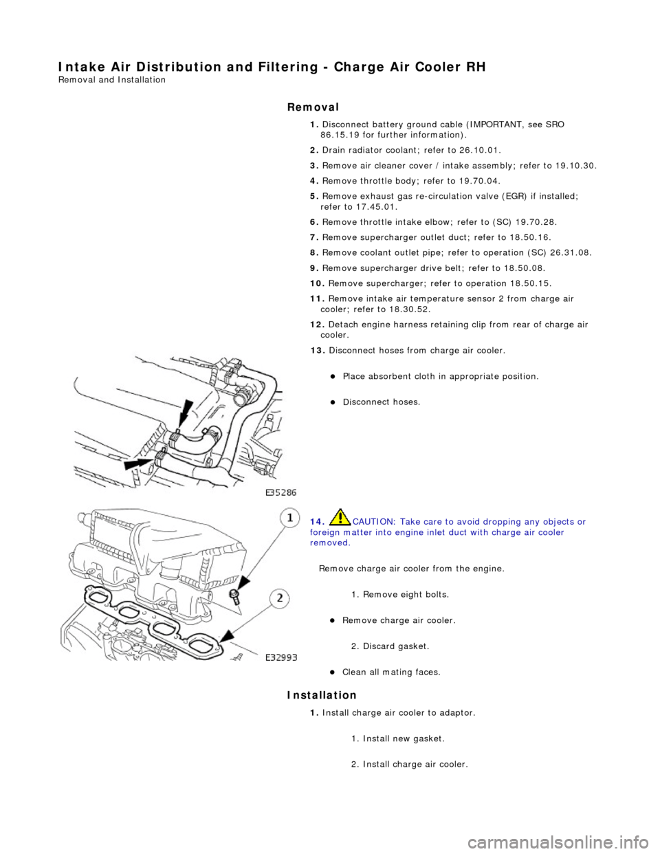
sconnect hoses from charge air cooler.
Pla
ce absorbent cloth in appropriate position.
Di
sc
onnect hoses.
14 . CAUTI
ON: Take care to avoi
d dropping any objects or
foreign matter into engine inle t duct with charge air cooler
removed.
Remove charge air cooler from the engine. 1. Remove eight bolts.
Remove charge air cooler.
2
. Discard gasket.
Cle
a
n all mating faces.
1.
Install ch arge air
cooler to adaptor.
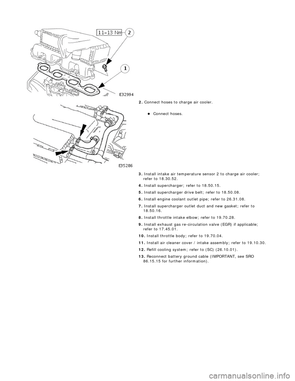
1. Install new gasket.
2. Install charge air cooler.
Page 1123 of 2490
2.
Conne
ct hoses to charge air cooler.
Conne
ct hoses.
3. Install intake air te mperature sensor 2 to charge air cooler;
refer to 18.30.52.
4. Install supercharger; refer to 18.50.15.
5. Install supercharger driv e belt; refer to 18.50.08.
6. Install engine coolant outlet pipe; refer to 26.31.08.
7. Install supercharger outlet du ct and new gasket; refer to
18.50.16.
8. Install throttle intake elbow; refer to 19.70.28.
9. Install exhaust gas re-circulation valve (EGR) if applicable;
refer to 17.45.01.
10. Install throttle body; refer to 19.70.04.
11. Install air cleaner cover / intake assembly; re fer to 19.10.30.
12. Refill cooling system; refer to (SC) (26.10.01).
13. Reconnect battery ground cable (IMPORTANT, see SRO
86.15.15 for further information).
Page 1128 of 2490
Intake Air Distribution and Filtering - Supercharger
Remo
val and Installation
Remov
a
l
Installation
1. Disc onne
ct battery ground cable (IMPORTANT, see SRO
86.15.19 for further information).
2. Drain radiator coolant; refer to 26.10.01.
3. Remove air cleaner cover / intake assembly; refer to 19.10.30.
4. Remove throttle body; refer to 19.70.04.
5. Remove exhaust gas re-circulation valve (EGR) if installed;
refer to 17.45.01.
6. Remove throttle intake elbo w; refer to (SC) 19.70.28.
7. Remove supercharger outlet duct; refer to 18.50.16.
8. Remove coolant outlet pipe; refe r to operation (SC) 26.31.08.
9. Remove supercharger drive belt; refer to 18.50.08.
10. Disconnect remaining coolant hoses from charge air coolers.
Position pipes to facilitate removal
of supercharger.
Inst
al
l suitable blanking plugs.
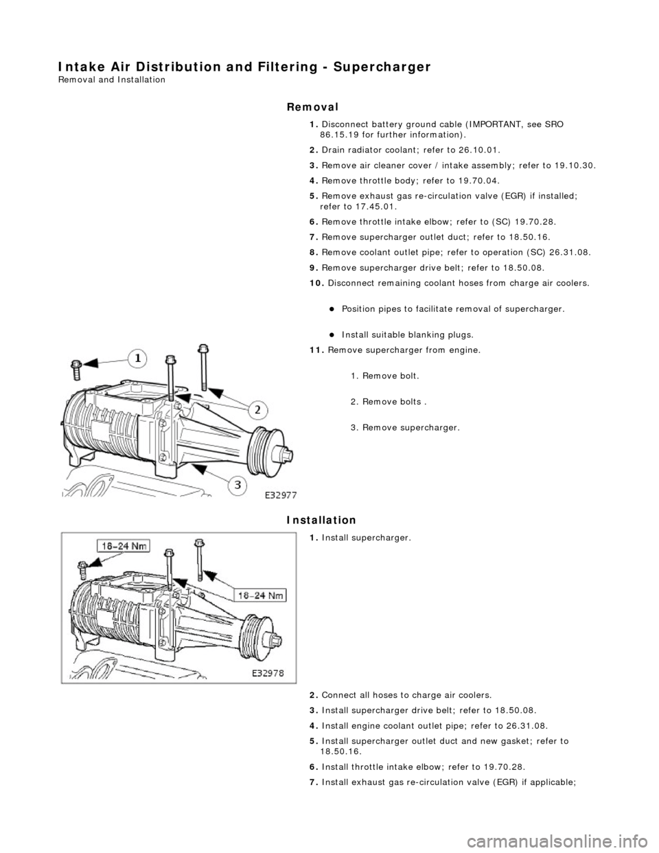
11 .
R
emove supercharger from engine.
1. Remove bolt.
2. Remove bolts .
3. Remove supercharger.
1. Inst al
l supercharger.
2. Connect all hoses to charge air coolers.
3. Install supercharger driv e belt; refer to 18.50.08.
4. Install engine coolant outlet pipe; refer to 26.31.08.
5. Install supercharger outlet du ct and new gasket; refer to
18.50.16.
6. Install throttle intake elbow; refer to 19.70.28.
7. Install exhaust gas re-circulation valve (EGR) if applicable;
Page 1161 of 2490
E
vaporative Emissions - Evaporative Emissions
D
iagnosis and Testing
Prelim
inary Inspection
1.
1. Vis
ually inspect for obvious signs of mechanical or electrical damage.
V
isual Inspection Chart
2.
2. If
an obvious cause for an observed or
reported concern is found, correct th e cause (if possible) before proceeding
to the next step.
3. 3. If the concern is not visually evident, verify the symptom and proceed with diagnosis, using the Jaguar approved
diagnostic system, where available.
4. 4. Where K-Line or Vacutec equipment is available, it should be used as an aid to diagnosis. The equipment must be
capable of testing to the 0.020 thou standard (2001 MY on).
Diagnostic Drive Cycles
Following th
e setting of a DTC, the appropriate repairs must
be carried out, and the normal operation of the system
checked. This will be done by performing a series of drive cycles which will enable the vehicle to operate the evaporative
emissions system as a function check. For details of the drive cycles,
REFER to Section 303
-1
4 Electronic Engine Controls
.
ECM adapt
ations.
Diagnostic Trouble Code
(D
TC) index/Symptom Chart
1.
1. Wh
ere the Jaguar approved diagnostic sy
stem is available, complete the S93 report before clearing any or all fault
codes from the vehicle.
• NOTE: If a DTC cannot be cleared, then there is a permanent fault present that flag s again as soon as it is cleared. (The
exception to this is P1260, which will only clear following an ignition OFF/ON cycle after rectification).
2. 2. If the cause is not visually evident and the Jaguar approv ed diagnostic system is not available, use a fault code
reader to retrieve the fault codes be fore proceeding to the Diagnostic Trou ble Code (DTC) Index Chart, or the
Symptom Chart if no DTCs are set.
3. 3. Using the Jaguar approved diagnostic system where available, and a scan tool where not, check the freeze frame
data for information on the conditions applicable when the fault was flagged. The format of this will vary,
depending on the tool used, but can pr ovide information useful to the technician in diagnosing the fault.
CAUTION: When probing connectors to take measurements in the course of the pinpoint tests, use the adaptor kit,
part number 3548-1358-00.
• NOTE: When performing electrical voltag e or resistance tests, always use a digital multimeter (DMM) accurate to 3
decimal places, and with an up-t o-date calibration certificate. When testing resistance, always take the resistance of the
DMM leads into account.
• NOTE: Check and rectify basic faults before beginning diagnostic ro utines involving pinpoint tests.
MechanicalElectrical
Engi
ne oil level
Coo
ling system coolant level
Fue
l level
Fuel contaminatio
n
/grade/quality
Throttle body Poly
-vee belt
F
uses
W
iring harness
E
lectrical connector(s)
Sens
or(s)
Engine
control module (ECM)
Page 1189 of 2490
E
lectronic Engine Controls -
Electronic Engine Controls
D
iagnosis and Testing
I
nspection and Verification
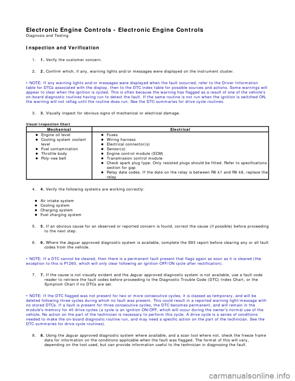
1.
1. Veri
fy the customer concern.
2. 2. Confirm which, if any, warning li ghts and/or messages were displayed on the instrument cluster.
• NOTE: If any warning lights and/or me ssages were displayed when the fault occurred, refer to the Driver Information
table for DTCs associated with the display, then to the DTC index table for possible sources and actions. Some warnings will
appear to clear when the ignition is cycl ed. This is often because the warning has flagged as a resu lt of one of the vehicle's
on-board diagnostic routines having run to detect the fault. If the same routine is not run when the ignition is switched ON,
the warning will not reflag until the routine does run. See the DTC summaries for drive cycle routines.
3. 3. Visually inspect for obvious signs of mechanical or electrical damage.
V
isual Inspection Chart
4.
4. Veri
fy the following syst
ems are working correctly:
Air in
take system
Coo
ling system
Charging system
F
uel charging system
5. 5. If an obvious cause for an observed or reported concern is found, correct the cause (if possible) before proceeding
to the next step.
6. 6. Where the Jaguar approved diagnostic sy stem is available, complete the S93 report before clearing any or all fault
codes from the vehicle.
• NOTE: If a DTC cannot be cleared, then there is a permanent fault present that flag s again as soon as it is cleared (the
exception to this is P1260, which will only clear following an ignition OFF/ON cycle after rectification).
7. 7. If the cause is not visually evident and the Jaguar approv ed diagnostic system is not available, use a fault code
reader to retrieve the fault codes be fore proceeding to the Diagnostic Trou ble Code (DTC) Index Chart, or the
Symptom Chart if no DTCs are set.
• NOTE: If the DTC flagged was not present for two or more co nsecutive cycles, it is classed as temporary, and will be
deleted following three cycl es during which no fault was present. This could result in a reported wa rning light/message with
no stored DTCs. If a fault is present for three consecutive cycles, the DTC becomes permanent, and will remain in the
module's memory for 40 drive cycles (a cy cle is an ignition ON/OFF, which will occur during the owner's normal use of the
vehicle. No action on the part of the technician is necessary to perform this cycle. A drive cycle is a series of conditions
needed to make the on-board diagnostic ro utine run, and may need a specific action on the part of the technician. See the
DTC summaries for driv e cycle routines).
8. 8. Using the Jaguar approved diagnostic system where available, and a scan tool where not, check the freeze frame
data for information on the conditions applicable when the fault was flagged. The format of this will vary,
dependin
g o
n the tool used, but can provide information useful to the technician in dia
gnos
in
g th
e fault.
MechanicalElectrical
Engi
ne oil level
Coo
ling system coolant
level
Fuel contamination
Throttle body Poly
-vee belt
F
uses
W
iring harness
E
lectrical connector(s)
Sens
or(s)
Engine
control module (ECM)
Tran
smission control module
Check spark plu
g type. Only re
sisted plugs should be fitted. Refer to specifications
section for gap
Relay date codes.
If the date on the rela
y is between R6 k1 and R6 k8, replace the
relay
Page 1759 of 2490
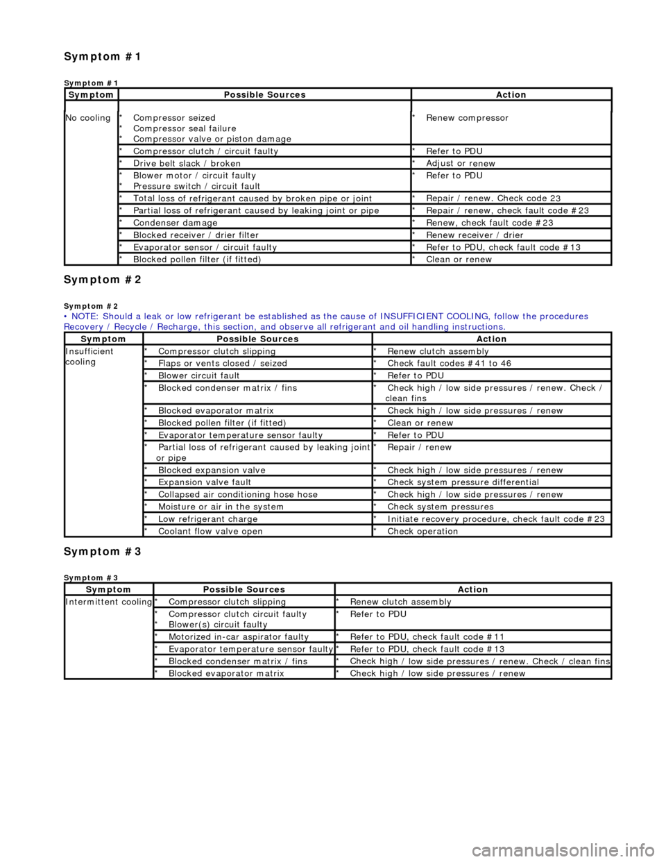
Sym
ptom #2
Sy
mptom #2
Sym
ptom #3
Sy
mptom #3
No
cooling
Compressor sei
zed
Compressor seal failure
Compressor valve or piston damage
*
*
*
R
enew compressor
*
Compressor cl
utch / circuit faulty
*
R
efer to PDU
*
D
rive belt slack / broken
*
Adjust or r
enew
*
B
lower motor / circuit faulty
Pressure switch / circuit fault
*
*
R
efer to PDU
*
Total l
oss of refrigerant caused by broken pipe or joint
*
Repair / renew. Check code 2
3
*
P
artial loss of refrigerant caused by leaking joint or pipe
*
R
epair / renew, check fault code #23
*
Conden
ser damage
*
Re
new, check fault code #23
*
Bl
ocked receiver / drier filter
*
R
enew receiver / drier
*
Evaporator senso
r / circuit faulty
*
R
efer to PDU, check fault code #13
*
Bl
ocked pollen filter (if fitted)
*
Cle
an or renew
*
• NOTE: Should a leak or low refrigerant be established as the cause of INSUFFICIENT COOL ING, follow the procedures
Recovery / Recycle / Recharge, this section, and ob serve all refrigerant and oil handling instructions.
Sy
mptom
Possib
le Sources
Acti
on
Insuffi
cient
cooling
Compre
ssor clutch slipping
*
R
enew clutch assembly
*
Fl
aps or vents closed / seized
*
Check f
ault codes #41 to 46
*
Bl
ower circuit fault
*
R
efer to PDU
*
Bl
ocked condenser matrix / fins
*
Check hig
h / low side pr
essures / renew. Check /
clean fins
*
Bl
ocked evaporator matrix
*
Check hig
h / low side
pressures / renew
*
Bl
ocked pollen filter (if fitted)
*
Cle
an or renew
*
Evaporator temp
erat
ure sensor faulty
*
R
efer to PDU
*
P
artial loss of refrigerant caused by leaking joint
or pipe
*
R
epair / renew
*
Blocked expan
sion valve
*
Check hig
h / low side
pressures / renew
*
Expans
ion valve fault
*
Chec
k system pres
sure differential
*
C
ollapsed air conditioning hose hose
*
Check hig
h / low side
pressures / renew
*
Moi
sture or air in the system
*
Chec
k system pressures
*
Low r
efrigerant charge
*
Initiate recovery
procedure, check fault code #23
*
Coo
lant flow valve open
*
Chec
k operation
*
Sy
mptom
Possib
le Sources
Acti
on
Int
ermittent cooling
Compre
ssor clutch slipping
*
R
enew clutch assembly
*
Compressor cl
utch circuit faulty
Blower(s) circuit faulty
*
*
R
efer to PDU
*
Motorized in-car aspirator faulty
*
R
efer to PDU, check fault code #11
*
Evaporator temp
erature sensor faulty
*
R
efer to PDU, check fault code #13
*
Bl
ocked condenser matrix / fins
*
Check hig
h / low side pressures / renew. Check / clean fins
*
Bl
ocked evaporator matrix
*
Check hig
h / low side
pressures / renew
*
Sym
ptom #1
Sy
mptom #1
Sy
mptom
Possib
le Sources
Acti
on
Page 1760 of 2490
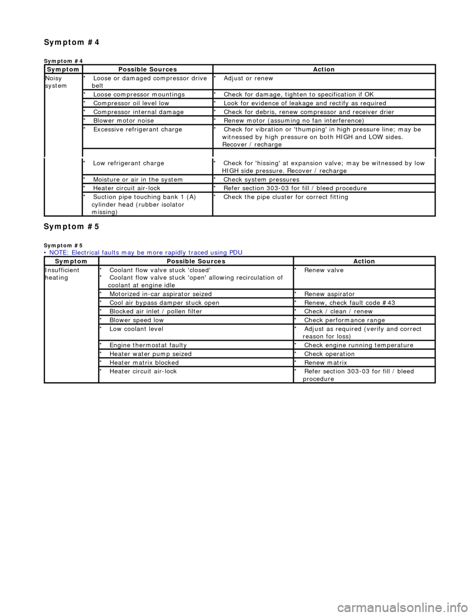
Symp
tom #5
Sy
m
ptom #5
Low r
e
frigerant charge
*
Check f or 'hissi
ng' at expansion
valve; may be witnessed by low
HIGH side pressure. Recover / recharge
*
Moi
s
ture or air in the system
*
Chec k syst
em pressures
*
Heat er ci
rcuit air-lock
*
R e
fer section 303-03 for fill / bleed procedure
*
Suct ion
pipe touching bank 1 (A)
cylinder head (rubber isolator
missing)
*
Check the pi
pe cluster for correct fitti
ng
*
• NOTE: Electrical faults may be more rapidly traced using PDU
Sym
ptom
Possib
l
e Sources
Acti
o
n
Insuffi
ci
ent
heating
Coo l
ant flow valve stuck 'closed'
Coolant flow valve stuck 'open' allowing recirculation of
coolant at engine idle
*
*
Re
new v
alve
*
Motorized in-car aspirator sei zed
*R e
new aspirator
*
Coo l
air bypass damper stuck open
*
Re new,
check fault code #43
*
B l
ocked air inlet / pollen filter
*
Chec k / cl
ean / renew
*
B l
ower speed low
*
Check performance range
*
Low cool ant
level
*
Adjust as req u
ired (verify and correct
reason for loss)
*
Engine
t
hermostat faulty
*
Check engine r u
nning temperature
*
Heater water pump seized
*Chec k op
eration
*
Heater ma trix
blocked
*
Re new m
atrix
*
Heater circui t
air-lock
*
R e
fer section 303-03 for fill / bleed
procedure
*
Sym
p
tom #4
Sym
ptom #4
Sy
m
ptom
Possib
l
e Sources
Acti
o
n
No
i
sy
system
Loose or damaged compressor drive
belt
*Adjust or r
e
new
*
Loose compressor mountings
*Check f o
r damage, tighten to specification if OK
*
Compressor oil level l
ow
*
Look for evidence of l
eakag
e and rectify as required
*
Compressor internal dama ge
*Check f o
r debris, renew compressor and receiver drier
*
B l
ower motor noise
*
Re new m
otor (assuming no fan interference)
*
Excessive refrige rant charge
*Check f o
r vibration or 'thumping'
in high pressure line; may be
witnessed by high pressure on both HIGH and LOW sides.
Recover / recharge
*
Page 1800 of 2490
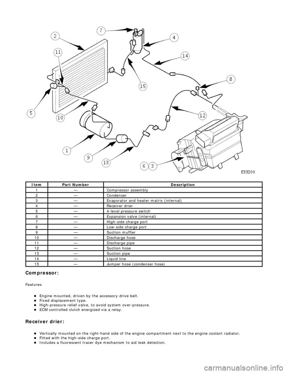
Compressor:
Features
Engine mounted, driven by the accessory drive belt. Fixed displacement type. High-pressure relief valve, to avoid system over-pressure. ECM controlled clutch energized via a relay.
Receiver drier:
Vertically mounted on the ri ght-hand side of the engine compartment next to the engine coolant radiator. Fitted with the high-side charge port. Includes a fluorescent tracer dye me chanism to aid leak detection.
ItemPart NumberDescription
1—Compressor assembly
2—Condenser
3—Evaporator and heater matrix (internal)
4—Receiver drier
5—4-level pressure switch
6—Expansion valve (internal)
7—High-side charge port
8—Low-side charge port
9—Suction muffler
10—Discharge hose
11—Discharge pipe
12—Suction hose
13—Suction pipe
14—Liquid line
15—Jumper hose (condenser hose)