Page 1804 of 2490
Air Conditioning - Air Conditioning (A/C) Compressor
Removal and Installation
Removal
1. Disconnect battery ground cable (IMPORTANT, see SRO
86.15.19 for further information).
2. Recover refrigerant from air co nditioning system; refer to
82.30.30.
3. Remove supercharger drive belt (where fitted); refer to
18.50.08.
4. Remove front end accessory dr ive belt; refer to 12.10.40 or
(SC) 12.10.40.
5. NOTE: A commercially availa ble brake pipe clamp is
recommended. Do not over tighten.
Clamp power steering reservoir to pump feed hose.
6. Raise vehicle for access
7. NOTE: Position drain tin to collect the fluid when union nut is
released.
Disconnect steering rack hose from pump. 1. Release union nut.
2. Discard O-ring.
3. Install suitable blanking plugs.
8. Disconnect clutch harness connector from compressor.
1. Disconnect connector.
9. Disconnect lines from compressor.
Discard O-rings.
Install suitable blanking plugs.
Page 1807 of 2490
8. Install front end accessory drive belt; refer to 12.10.40 or (SC)
12.10.40.
9. Install supercharger drive belt (where fitted); refer to
18.50.08.
10. Reconnect battery ground cable (IMPORTANT, see SRO
86.15.15 for further information).
11. Recharge air conditioning system; refer to 82.30.30.
12. Check / bleed / top up power stee ring fluid reservoir; refer to
211-02.
Page 1837 of 2490
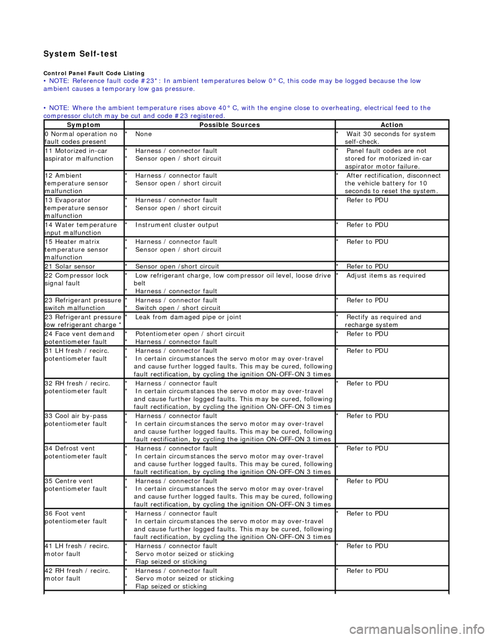
System Self-test
Control Panel Fault Code Listing • NOTE: Reference fault code #23*: In ambient temperatures below 0° C, this code may be logged because the low
ambient causes a tempor ary low gas pressure.
• NOTE: Where the ambient temperature rises above 40° C, with the engine close to overheating, electrical feed to the
compressor clutch may be cut and code #23 registered.
SymptomPossible SourcesAction
0 Normal operation no
fault codes presentNone
*Wait 30 seconds for system
self-check.
*
11 Motorized in-car
aspirator malfunctionHarness / connector fault
Sensor open / short circuit
*
*Panel fault codes are not
stored for motorized in-car
aspirator motor failure.
*
12 Ambient
temperature sensor
malfunctionHarness / connector fault
Sensor open / short circuit
*
*After rectification, disconnect
the vehicle battery for 10
seconds to reset the system.
*
13 Evaporator
temperature sensor
malfunctionHarness / connector fault
Sensor open / short circuit
*
*Refer to PDU
*
14 Water temperature
input malfunctionInstrument cl uster output
*Refer to PDU
*
15 Heater matrix
temperature sensor
malfunctionHarness / connector fault
Sensor open / short circuit
*
*Refer to PDU
*
21 Solar sensorSensor open /short circuit
*Refer to PDU
*
22 Compressor lock
signal faultLow refrigerant charge, low compressor oil level, loose drive
belt Harness / connector fault
*
*Adjust items as required
*
23 Refrigerant pressure
switch malfunctionHarness / connector fault
Switch open / short circuit
*
*Refer to PDU
*
23 Refrigerant pressure
low refrigerant charge * Leak from damaged pipe or joint
*Rectify as required and
recharge system
*
24 Face vent demand
potentiometer faultPotentiometer open / short circuit
Harness / connector fault
*
*Refer to PDU
*
31 LH fresh / recirc.
potentiometer faultHarness / connector fault
In certain circumstances the servo motor may over-travel
and cause further logged faults. This may be cured, following
fault rectification, by cycling the ignition ON-OFF-ON 3 times
*
*Refer to PDU
*
32 RH fresh / recirc.
potentiometer faultHarness / connector fault
In certain circumstances the servo motor may over-travel
and cause further logged faults. This may be cured, following
fault rectification, by cycling the ignition ON-OFF-ON 3 times
*
*Refer to PDU
*
33 Cool air by-pass
potentiometer faultHarness / connector fault
In certain circumstances the servo motor may over-travel
and cause further logged faults. This may be cured, following
fault rectification, by cycling the ignition ON-OFF-ON 3 times
*
*Refer to PDU
*
34 Defrost vent
potentiometer faultHarness / connector fault
In certain circumstances the servo motor may over-travel
and cause further logged faults. This may be cured, following
fault rectification, by cycling the ignition ON-OFF-ON 3 times
*
*Refer to PDU
*
35 Centre vent
potentiometer faultHarness / connector fault
In certain circumstances the servo motor may over-travel
and cause further logged faults. This may be cured, following
fault rectification, by cycling the ignition ON-OFF-ON 3 times
*
*Refer to PDU
*
36 Foot vent
potentiometer faultHarness / connector fault
In certain circumstances the servo motor may over-travel
and cause further logged faults. This may be cured, following
fault rectification, by cycling the ignition ON-OFF-ON 3 times
*
*Refer to PDU
*
41 LH fresh / recirc.
motor faultHarness / connector fault
Servo motor seized or sticking
Flap seized or sticking
*
*
*Refer to PDU
*
42 RH fresh / recirc.
motor faultHarness / connector fault
Servo motor seized or sticking
Flap seized or sticking
*
*
*Refer to PDU
*
Page 1855 of 2490
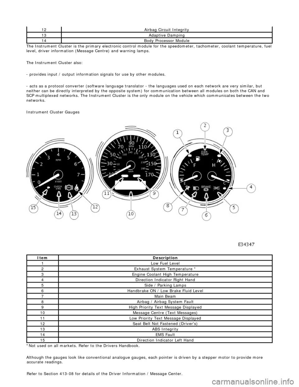
The In
strument Cluster is the primary electronic control module for the speedomete
r, tachometer, coolant temperature, fuel
level, driver information (Message Centre) and warning lamps.
The Instrument Cluster also:
- provides input / output informatio n signals for use by other modules.
- acts as a protocol converter (software language translator - the languages used on each network are very similar, but
neither can be directly interp reted by the opposite system) for communication between all modules on both the CAN and
SCP multiplexed networks. The Instrument Cluster is the only module on the vehicle which communicates between the two
networks.
Instrument Cluster Gauges
*Not used on all markets. Refer to the Drivers Handbook.
Although the gauges look like conventional analogue gauges, each pointer is driven by a stepper motor to provide more
12Ai
rbag Circuit Integrity
13Adaptive Damping
14Body Processor
Module
It
em
De
scription
1Low Fu
el Level
2Exhaus
t System Temperature *
3E
ngine Coolant High Temperature
4Di
rection Indicator Right Hand
5Side
/ Parking Lamps
6Handbrake ON / Low
Bra
ke Fluid Level
7Main
Beam
8Ai
rbag / Airbag System Fault
9Hi
gh Priority Text
Message Displayed
10M
essage Centre (Text Messages)
11Low Pri
ority Text Message Displayed
12Se
at Belt Not Fa
stened (Driver's)
13ABS Integrity
14EMS Fault
15D
irection Indicator Left Hand
accu
rate readings.
Refer to Section 413-08 for details of the Driver Information / Message Center.
Page 1882 of 2490
Generator and Regulator - Generator
Description and Operation
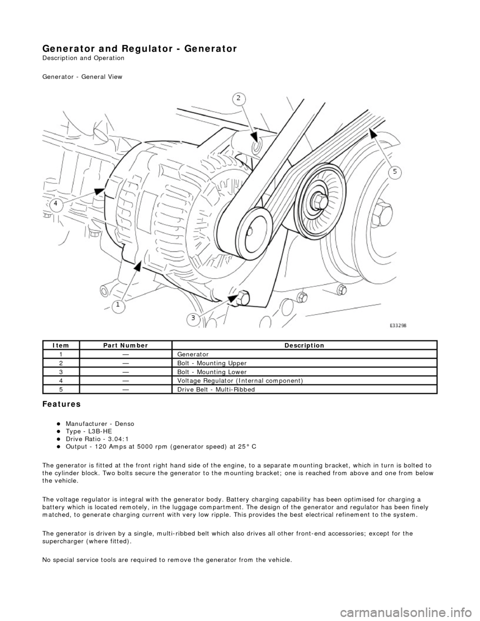
Generator - General View
Features
Manufacturer - Denso Type - L3B-HE Drive Ratio - 3.04:1 Output - 120 Amps at 5000 rpm (generator speed) at 25° C
The generator is fitted at the front right hand side of the engine, to a sepa rate mounting bracket, which in turn is bolted to
the cylinder block. Two bolts secure th e generator to the mounting bracket; one is reached from above and one from below
the vehicle.
The voltage regulator is integral with th e generator body. Battery charging capabi lity has been optimised for charging a
battery which is located remotely, in the luggage compartment. The design of the generator and regulator has been finely
matched, to generate charging current with very low ripple. This provides the best electrical refinement to the system.
The generator is driven by a single, multi-ribbed belt which also drives all other front-e nd accessories; except for the
supercharger (where fitted).
No special service tools are required to remove the generator from the vehicle.
ItemPart NumberDescription
1—Generator
2—Bolt - Mounting Upper
3—Bolt - Mounting Lower
4—Voltage Regulator (Internal component)
5—Drive Belt - Multi-Ribbed
Page 1883 of 2490
Belt tension is achieved by an automatic tensioner; neither the belt nor the tensioner require service apart from checking
the belt wear indicators at each normal service interval.
The minimum service life of the drive belt is 100,000 miles.
Never apply oil to the belt or to the belt tensioner.
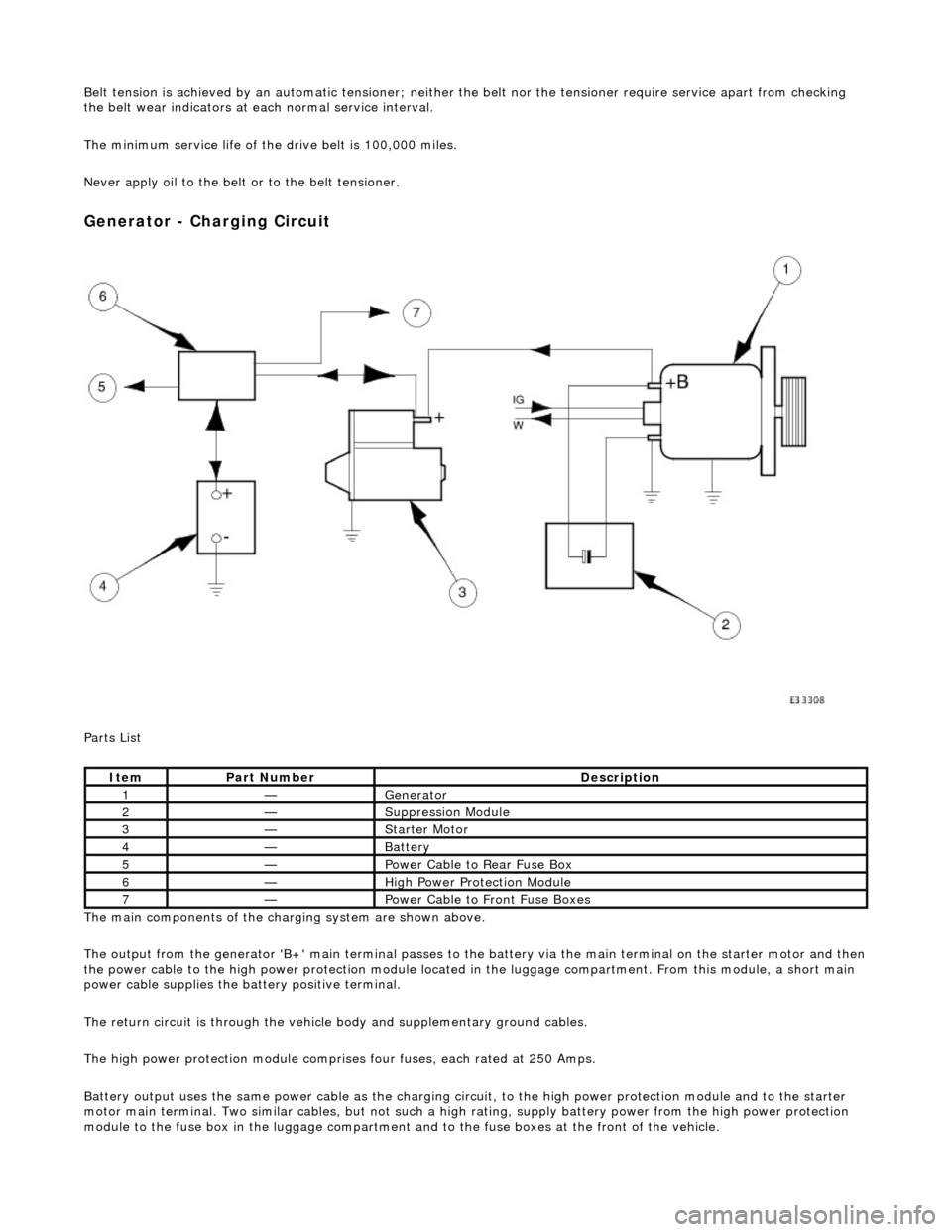
Generator - Charging Circuit
Parts List
The main components of the charging system are shown above.
The output from the generator 'B+' main te rminal passes to the battery via the main terminal on the starter motor and then
the power cable to the high power protection module located in the luggage compartment. From this module, a short main
power cable supplies the ba ttery positive terminal.
The return circuit is through the vehicle body and supplementary ground cables.
The high power protection mo dule comprises four fuses, each rated at 250 Amps.
Battery output uses the same power cable as the charging circ uit, to the high power protection module and to the starter
motor main terminal. Two similar cables, but not such a high rating, supply battery power from the high power protection
module to the fuse box in the luggage compartment an d to the fuse boxes at the front of the vehicle.
ItemPart NumberDescription
1—Generator
2—Suppression Module
3—Starter Motor
4—Battery
5—Power Cable to Rear Fuse Box
6—High Power Protection Module
7—Power Cable to Front Fuse Boxes
Page 1885 of 2490
If the field were not controlled, the 'B+' output would rise to a level which could damage bulbs and ECMs. The regulator
compares the output voltage to an intern al voltage reference circuit to achieve the controlled output of the generator.
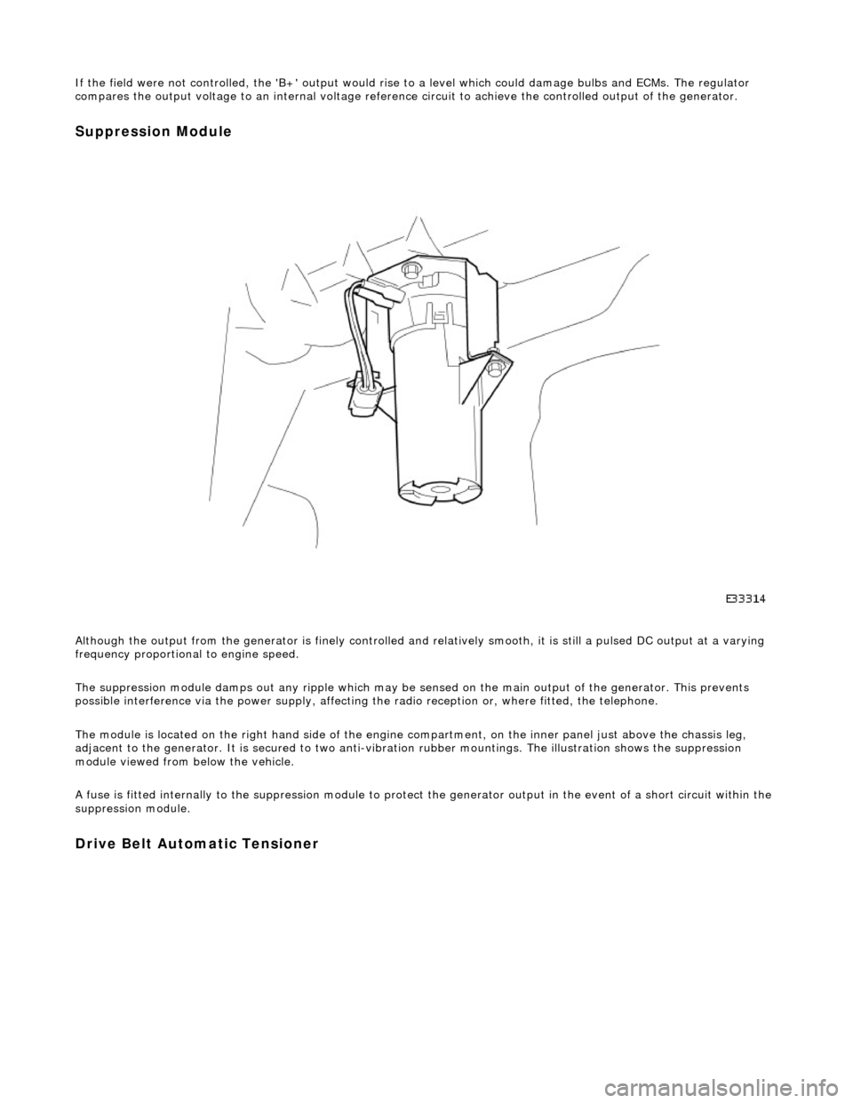
Suppression Module
Although the output from the generator is fi nely controlled and relatively smooth, it is still a pulsed DC output at a varying
frequency proportional to engine speed.
The suppression module damps ou t any ripple which may be sensed on the main output of the generator. This prevents
possible interference via the power supply, affecting the radio reception or, where fitted, the telephone.
The module is located on the right hand side of the engine compartment, on the inner panel just above the chassis leg,
adjacent to the generator. It is secured to two anti-vibration rubber moun tings. The illustration shows the suppression
module viewed from below the vehicle.
A fuse is fitted internally to the suppression module to protect the generator output in the event of a short circuit within th e
suppression module.
Drive Belt Automatic Tensioner
Page 1886 of 2490
Belt tension is achieved by an automatic tensioner; neither the belt nor the tensioner require service apart from checking
the belt wear indicators at each normal service interval.
The minimum service life of the drive belt is 100,000 miles.
Never apply oil to the belt or to the belt tensioner.
ItemDescription
1New Belt - Minimum Length
2New Belt - Maximum Length
3Replace the Belt