1998 ISUZU TROOPER charging
[x] Cancel search: chargingPage 1715 of 3573
CHARGING SYSTEM 6D3 Ð 9
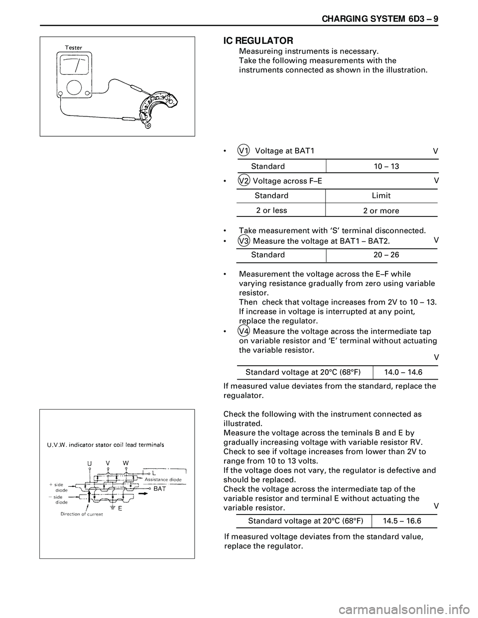
IC REGULATOR
Measureing instruments is necessary.
Take the following measurements with the
instruments connected as shown in the illustration.
¥ V1 Voltage at BAT1
¥ V2 Voltage across FÐE
¥ Take measurement with ÔSÕ terminal disconnected.
¥ V3 Measure the voltage at BAT1 Ð BAT2.
¥ Measurement the voltage across the EÐF while
varying resistance gradually from zero using variable
resistor.
Then check that voltage increases from 2V to 10 Ð 13.
If increase in voltage is interrupted at any point,
replace the regulator.
¥ V4 Measure the voltage across the intermediate tap
on variable resistor and ÔEÕ terminal without actuating
the variable resistor.
If measured value deviates from the standard, replace the
regualator.
Check the following with the instrument connected as
illustrated.
Measure the voltage across the teminals B and E by
gradually increasing voltage with variable resistor RV.
Check to see if voltage increases from lower than 2V to
range from 10 to 13 volts.
If the voltage does not vary, the regulator is defective and
should be replaced.
Check the voltage across the intermediate tap of the
variable resistor and terminal E without actuating the
variable resistor.
If measured voltage deviates from the standard value,
replace the regulator.
Standard 10 – 13
V
Standard Limit
2 or less
2 or more
V
Standard 20 – 26V
Standard voltage at 20°C (68°F) 14.0 – 14.6
V
Standard voltage at 20°C (68°F) 14.5 – 16.6
V
Page 1716 of 3573
6D3 Ð 10 CHARGING SYSTEM
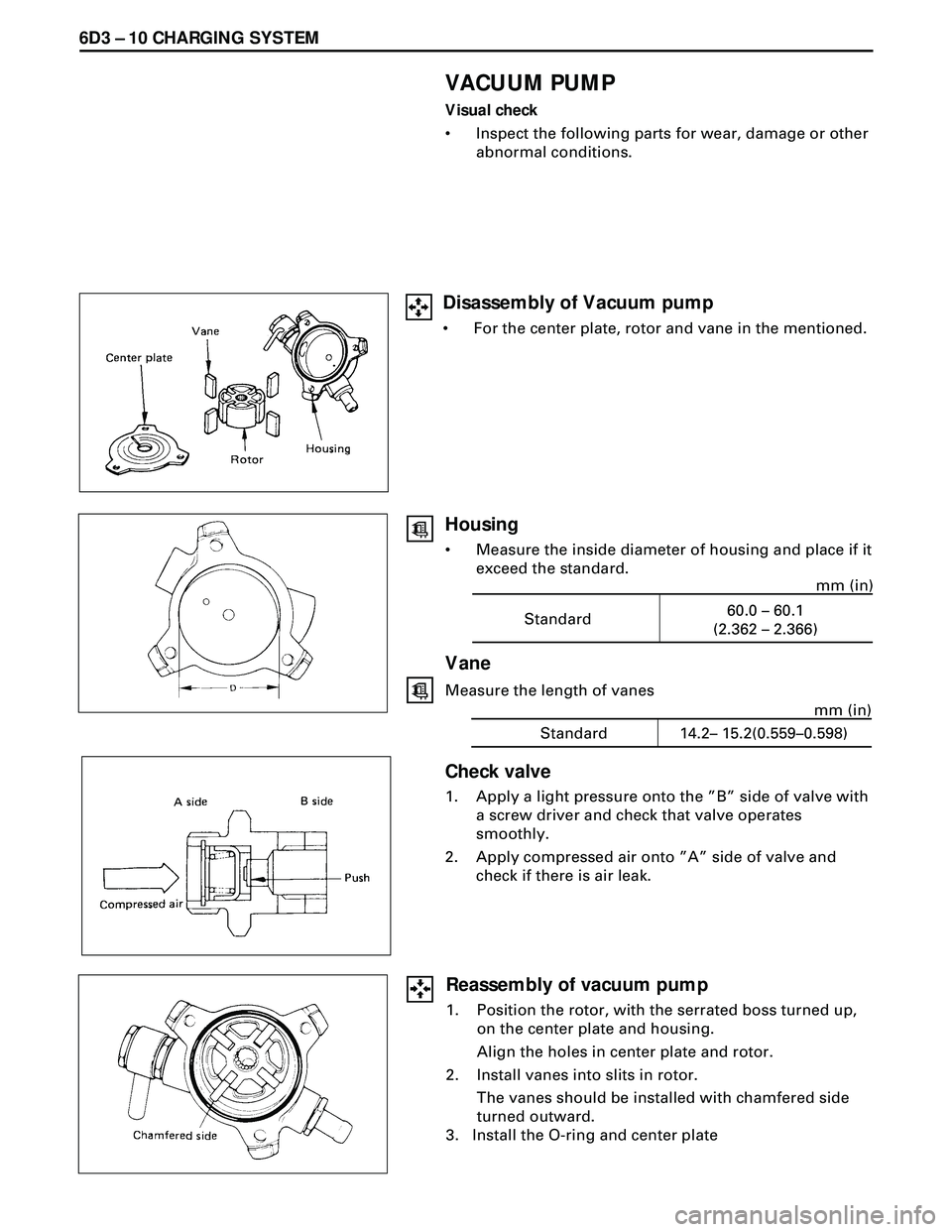
VACUUM PUMP
Visual check
¥ Inspect the following parts for wear, damage or other
abnormal conditions.
Standard60.0 – 60.1
(2.362 – 2.366)mm (in)
Vane
Measure the length of vanes
Standard 14.2– 15.2(0.559–0.598)mm (in)
Check valve
1. Apply a light pressure onto the ÓBÓ side of valve with
a screw driver and check that valve operates
smoothly.
2. Apply compressed air onto ÓAÓ side of valve and
check if there is air leak.
Housing
¥ Measure the inside diameter of housing and place if it
exceed the standard.
Reassembly of vacuum pump
1. Position the rotor, with the serrated boss turned up,
on the center plate and housing.
Align the holes in center plate and rotor.
2. Install vanes into slits in rotor.
The vanes should be installed with chamfered side
turned outward.
3. Install the O-ring and center plate
Disassembly of Vacuum pump
¥ For the center plate, rotor and vane in the mentioned.
Page 1717 of 3573
CHARGING SYSTEM 6D3 Ð 11
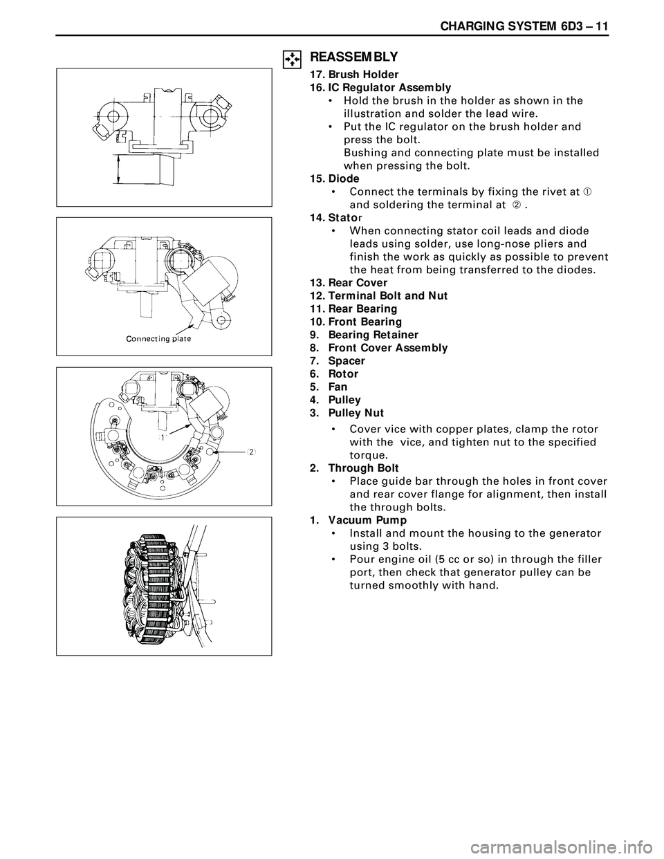
REASSEMBLY
17. Brush Holder
16. IC Regulator Assembly
¥ Hold the brush in the holder as shown in the
illustration and solder the lead wire.
¥ Put the IC regulator on the brush holder and
press the bolt.
Bushing and connecting plate must be installed
when pressing the bolt.
15. Diode
¥ Connect the terminals by fixing the rivet at À
and soldering the terminal at Á .
14. Stator
¥ When connecting stator coil leads and diode
leads using solder, use long-nose pliers and
finish the work as quickly as possible to prevent
the heat from being transferred to the diodes.
13. Rear Cover
12. Terminal Bolt and Nut
11. Rear Bearing
10. Front Bearing
9. Bearing Retainer
8. Front Cover Assembly
7. Spacer
6. Rotor
5. Fan
4. Pulley
3. Pulley Nut
¥ Cover vice with copper plates, clamp the rotor
with the vice, and tighten nut to the specified
torque.
2. Through Bolt
¥ Place guide bar through the holes in front cover
and rear cover flange for alignment, then install
the through bolts.
1. Vacuum Pump
¥ Install and mount the housing to the generator
using 3 bolts.
¥ Pour engine oil (5 cc or so) in through the filler
port, then check that generator pulley can be
turned smoothly with hand.
Page 1718 of 3573
6D3 Ð 12 CHARGING SYSTEM
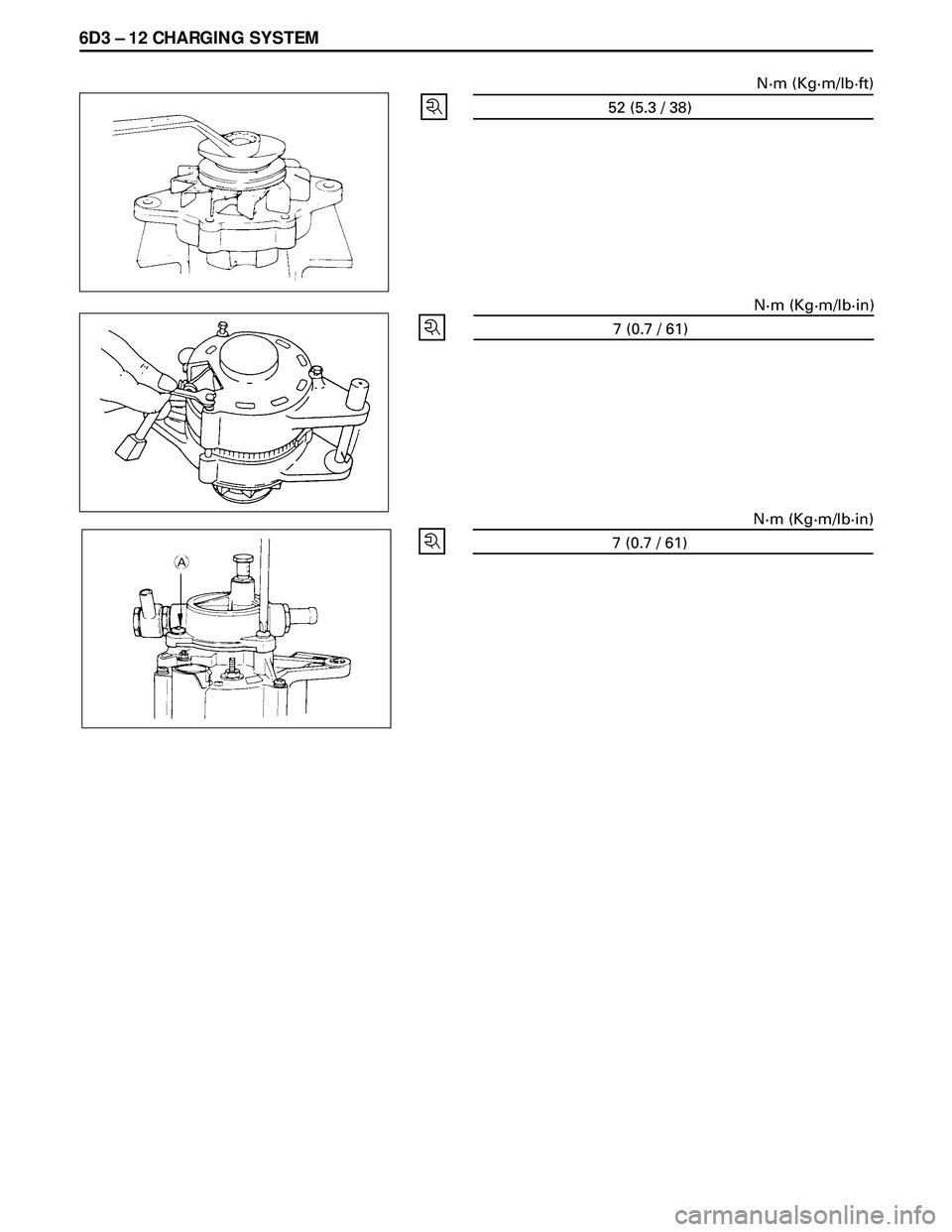
52 (5.3 / 38)N·m (Kg·m/lb·ft)
7 (0.7 / 61)N·m (Kg·m/lb·in)
7 (0.7 / 61)N·m (Kg·m/lb·in)
Page 1738 of 3573
ENGINE MECHANICAL 6A – 5
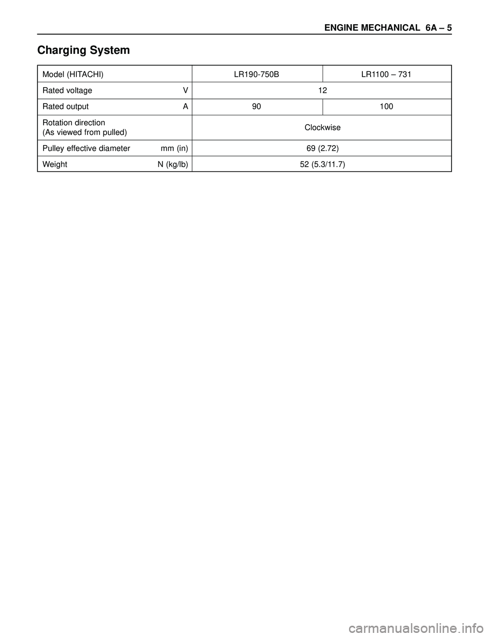
Charging System
Model (HITACHI) LR190-750B LR1100 – 731
Rated voltage V 12
Rated output A 90 100
Rotation direction
Clockwise
(As viewed from pulled)
Pulley effective diameter mm (in) 69 (2.72)
Weight N (kg/lb) 52 (5.3/11.7)
Page 1868 of 3573
ENGINE ELECTRICAL 6D – 1
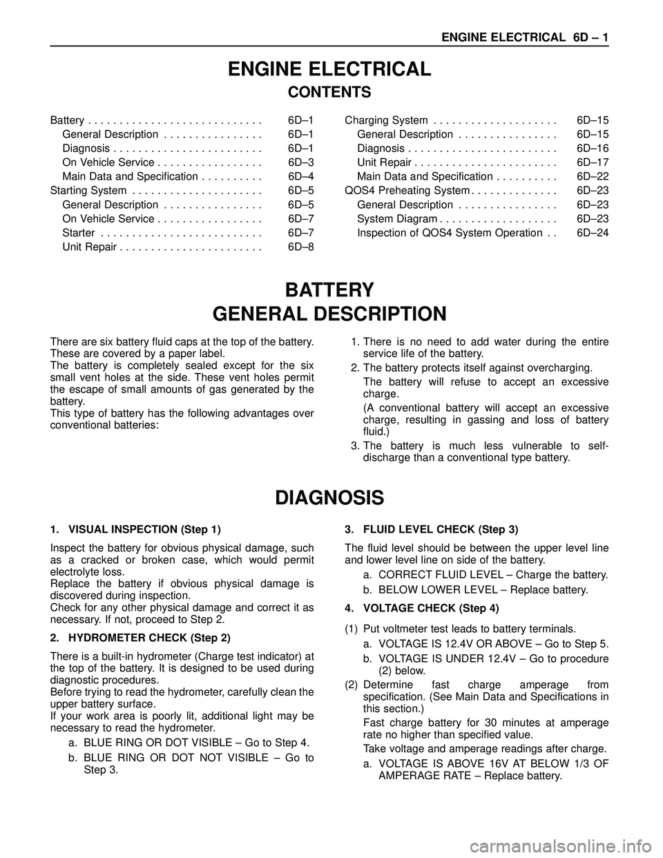
ENGINE ELECTRICAL
CONTENTS
Battery . . . . . . . . . . . . . . . . . . . . . . . . . . . . 6D–1
General Description . . . . . . . . . . . . . . . . 6D–1
Diagnosis . . . . . . . . . . . . . . . . . . . . . . . . 6D–1
On Vehicle Service . . . . . . . . . . . . . . . . . 6D–3
Main Data and Specification . . . . . . . . . . 6D–4
Starting System . . . . . . . . . . . . . . . . . . . . . 6D–5
General Description . . . . . . . . . . . . . . . . 6D–5
On Vehicle Service . . . . . . . . . . . . . . . . . 6D–7
Starter . . . . . . . . . . . . . . . . . . . . . . . . . . 6D–7
Unit Repair . . . . . . . . . . . . . . . . . . . . . . . 6D–8Charging System . . . . . . . . . . . . . . . . . . . . 6D–15
General Description . . . . . . . . . . . . . . . . 6D–15
Diagnosis . . . . . . . . . . . . . . . . . . . . . . . . 6D–16
Unit Repair . . . . . . . . . . . . . . . . . . . . . . . 6D–17
Main Data and Specification . . . . . . . . . . 6D–22
QOS4 Preheating System . . . . . . . . . . . . . . 6D–23
General Description . . . . . . . . . . . . . . . . 6D–23
System Diagram . . . . . . . . . . . . . . . . . . . 6D–23
Inspection of QOS4 System Operation . . 6D–24
BATTERY
GENERAL DESCRIPTION
DIAGNOSIS
There are six battery fluid caps at the top of the battery.
These are covered by a paper label.
The battery is completely sealed except for the six
small vent holes at the side. These vent holes permit
the escape of small amounts of gas generated by the
battery.
This type of battery has the following advantages over
conventional batteries:1. There is no need to add water during the entire
service life of the battery.
2. The battery protects itself against overcharging.
The battery will refuse to accept an excessive
charge.
(A conventional battery will accept an excessive
charge, resulting in gassing and loss of battery
fluid.)
3. The battery is much less vulnerable to self-
discharge than a conventional type battery.
1. VISUAL INSPECTION (Step 1)
Inspect the battery for obvious physical damage, such
as a cracked or broken case, which would permit
electrolyte loss.
Replace the battery if obvious physical damage is
discovered during inspection.
Check for any other physical damage and correct it as
necessary. If not, proceed to Step 2.
2. HYDROMETER CHECK (Step 2)
There is a built-in hydrometer (Charge test indicator) at
the top of the battery. It is designed to be used during
diagnostic procedures.
Before trying to read the hydrometer, carefully clean the
upper battery surface.
If your work area is poorly lit, additional light may be
necessary to read the hydrometer.
a. BLUE RING OR DOT VISIBLE – Go to Step 4.
b. BLUE RING OR DOT NOT VISIBLE – Go to
Step 3.3. FLUID LEVEL CHECK (Step 3)
The fluid level should be between the upper level line
and lower level line on side of the battery.
a. CORRECT FLUID LEVEL – Charge the battery.
b. BELOW LOWER LEVEL – Replace battery.
4. VOLTAGE CHECK (Step 4)
(1) Put voltmeter test leads to battery terminals.
a. VOLTAGE IS 12.4V OR ABOVE – Go to Step 5.
b. VOLTAGE IS UNDER 12.4V – Go to procedure
(2) below.
(2) Determine fast charge amperage from
specification. (See Main Data and Specifications in
this section.)
Fast charge battery for 30 minutes at amperage
rate no higher than specified value.
Take voltage and amperage readings after charge.
a. VOLTAGE IS ABOVE 16V AT BELOW 1/3 OF
AMPERAGE RATE – Replace battery.
Page 1869 of 3573
6D – 2 ENGINE ELECTRICAL
b. VOLTAGE IS ABOVE 16V AT ABOVE 1/3 OF
AMPERAGE RATE – Drop charging voltage to
15V and charge for 10 – 15 hours.
Then go to Step 5.
c. VOLTAGE IS BETWEEN 12V AND 16V –
Continue charging at the same rate for an
additional 3-1/2 hours. Then go to Step 5.
d. VOLTAGE IS BELOW 12V – Replace battery.
5. LOAD TEST (Step 5)
(1) Connect a voltmeter and a battery load tester
across the battery terminals.
(2) Apply 300 ampere load for 15 seconds to remove
surface charge from the battery.
Remove load.
(3) Wait 15 seconds to let battery recover. Then apply
specified load from specifications (See Main Data
and Specifications in this section).
Read voltage after 15 seconds, then remove load.
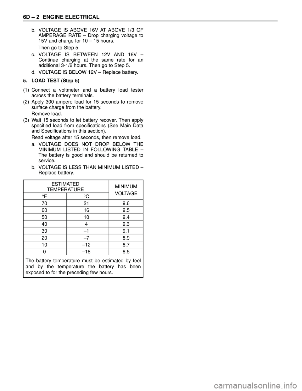
a. VOLTAGE DOES NOT DROP BELOW THE
MINIMUM LISTED IN FOLLOWING TABLE –
The battery is good and should be returned to
service.
b. VOLTAGE IS LESS THAN MINIMUM LISTED –
Replace battery.
ESTIMATED
TEMPERATUREMINIMUM
°F °CVOLTAGE
70 21 9.6
60 16 9.5
50 10 9.4
40 4 9.3
30 –1 9.1
20 –7 8.9
10 –12 8.7
0 –18 8.5
The battery temperature must be estimated by feel
and by the temperature the battery has been
exposed to for the preceding few hours.
Page 1870 of 3573
ENGINE ELECTRICAL 6D – 3
ON-VEHICLE SERVICE
BATTERY CHARGING
Observe the following safety precautions when
charging the battery:
1. Never attempt to charge the battery when the fluid
level is below the lower level line on the side of the
battery. In this case, the battery must be replaced.
2. Pay close attention to the battery during the
charging procedure.
Battery charging should be discontinued or the rate
of charge reduced if the battery feels hot to the
touch.
Battery charging should be discontinued or the rate
of charge reduced if the battery begins to gas or
spew electrolyte from the vent holes.
3. In order to more easily view the hydrometer blue
dot or ring, it may be necessary to jiggle or tilt the
battery.
4. Battery temperature can have a great effect on
battery charging capacity.
5. The sealed battery used on this vehicle may be
either quick-charged or slow-charged in the same
manner as other batteries.
Whichever method you decide to use, be sure that
you completely charge the battery. Never partially
charge the battery.
JUMP STARTING
JUMP STARTING WITH AN AUXILIARY
(BOOSTER) BATTERY
CAUTION: Never push or tow the vehicle in an
attempt to start it. Serious damage to the emission
system as well as other vehicle parts will result.
Treat both the discharged battery and the booster
battery with great care when using jumper cables.
Carefully follow the jump starting procedure, being
careful at all times to avoid sparking.
WARNING: Failure to carefully follow the jump
starting procedure could result in the following:
1. Serious personal injury, particularly to your
eyes.
2. Property damage from a battery explosion,
battery acid, or an electrical fire.
3. Damage to the electronic components of one or
both vehicles.
Never expose the battery to an open flame or electrical
spark. Gas generated by the battery may catch fire or
explode. Remove any rings, watches, or other jewelry
before working around the battery. Protect your eyes by
wearing an approved set of goggles.
Never allow battery fluid to come in contact with your
eyes or skin.
Never allow battery fluid to come in contact with fabrics
or painted surfaces.
Battery fluid is a highly corrosive acid.Should battery fluid come in contact with your eyes,
skin, fabric, or a painted surface, immediately and
thoroughly rinse the affected area with clean tap water.
Never allow metal tools or jumper cables to come in
contact with the positive battery terminal, or any other
metal surface of the vehicle. This will protect against a
short circuit.
Always keep batteries out of the reach of young
children.
JUMP STARTING PROCEDURE
1. Set the vehicle parking brake.
If the vehicle is equipped with an automatic
transmission, place the selector lever in the “PARK”
position.
If the vehicle is equipped with a manual
transmission place the shift lever in the “NEUTRAL”
position.
Turn “OFF” the ignition.
Turn “OFF” all lights and any other accessory
requiring electrical power.
2. Look at the built-in hydrometer.
If the indication area of the built-in hydrometer is
completely clear, do not try to jump start.
3. Attach the end of one jumper cable to the positive
terminal of the booster battery.
Attach the other end of the same cable to the
positive terminal of the discharged battery.
Do not allow the vehicles to touch each other.
This will cause a ground connection, effectively
neutralizing the charging procedure.
Be sure that the booster battery has a 12 volt rating.
4. Attach one end of the remaining cable to the
negative terminal of the booster battery.
Attach the other end of the same cable to a solid
engine ground (such as the A/C compressor
bracket or the generator mounting bracket) of the
vehicle with the discharged battery.
This ground connection must be at least 450 mm
(18 in) from the battery of the vehicle whose battery
is being charged.
WARNING: Never attach the end of the jumper
cable directly to the negative terminal of the dead
battery.
5. Start the engine of the vehicle with the good battery.
Make sure that all unnecessary electrical
accessories have been turned “OFF”.
6. Start the engine of the vehicle with the dead battery.
7. To remove the jumper cables, follow the above
directions in the reverse order.
Be sure to first disconnect the negative cable from
the vehicle with the discharged battery.