Page 1707 of 3573
CHARGING SYSTEM 6D3 Ð 1
SECTION 6D3
CHARGING SYSTEM
CONTENTS
PAGE
General Description ........................................................................................................ 6D3-1
Diagnosis ......................................................................................................................... 6D3-4
Unit Repair ....................................................................................................................... 6D3-5
GENERAL DESCRIPTION
The generator does not require particular
maintenance such as voltage adjustment. The
rectifier connected to the stator coil has nine diodes
to transform A.C. voltage into D.C. voltage. This
D.C. voltage is connected to the output terminal of
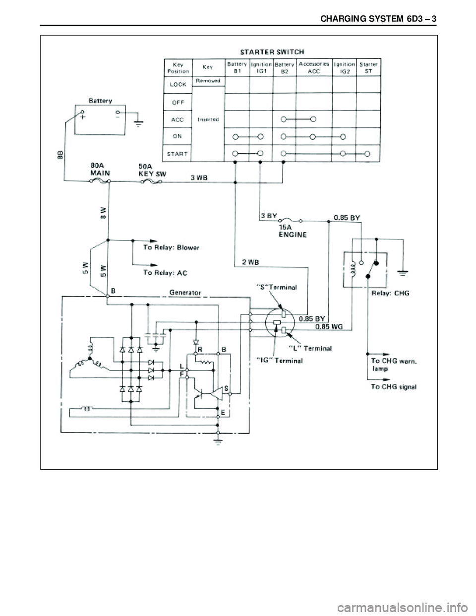
generator. The charging system is the IC integral regulator
charging system and its main components are
connected as shown in Figure.
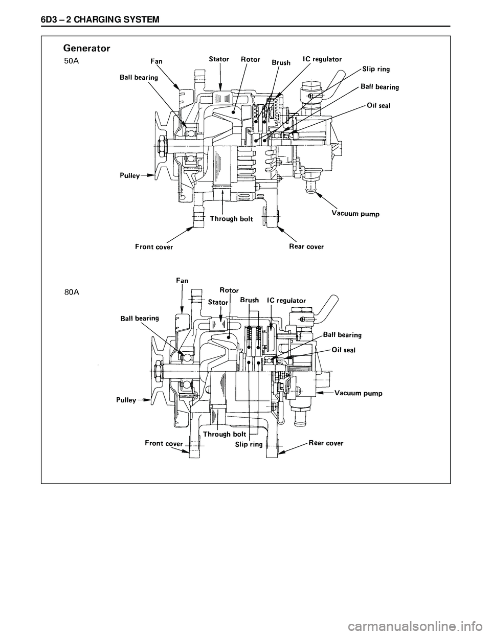
The regulator is a solid state type and it is mounted
along with the brush holder assembly inside the
generator installed on the rear end cover.
Page 1708 of 3573
Page 1709 of 3573
Page 1710 of 3573
6D3 Ð 4 CHARGING SYSTEM
DIAGNOSIS
GENERAL ON-VEHICLE INSPECTION
The operating condition of charging system is indicated
by the charge warning lamp. The warning lamp comes on
when the starter switch is turned to ÒONÓ position. The
charging system operates normally if the lamp goes off
when the engine starts. If the warning lamp shows
abnormality or if undercharged or overcharged battery
condition is suspected, perform diagnosis by checking the
charging system as follows:
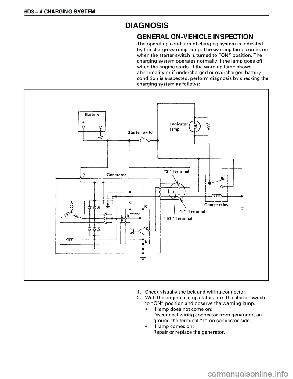
1. Check visually the belt and wiring connector.
2. With the engine in stop status, turn the starter switch
to ÒONÓ position and observe the warning lamp.
·If lamp does not come on:
Disconnect wiring connector from generator, an
ground the terminal ÒLÓ on connector side.
·If lamp comes on:
Repair or replace the generator.
Page 1711 of 3573
CHARGING SYSTEM 6D3 Ð 5
UNIT REPAIR
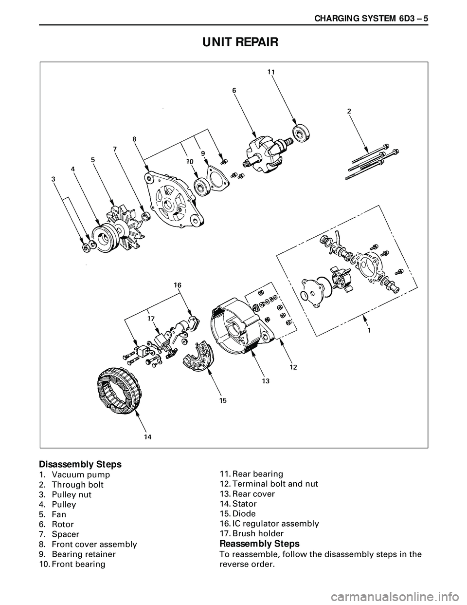
Disassembly Steps
1. Vacuum pump
2. Through bolt
3. Pulley nut
4. Pulley
5. Fan
6. Rotor
7. Spacer
8. Front cover assembly
9. Bearing retainer
10. Front bearing11. Rear bearing
12. Terminal bolt and nut
13. Rear cover
14. Stator
15. Diode
16. IC regulator assembly
17. Brush holder
Reassembly Steps
To reassemble, follow the disassembly steps in the
reverse order.
Page 1712 of 3573
6D3 Ð 6 CHARGING SYSTEM
DISASSEMBLY
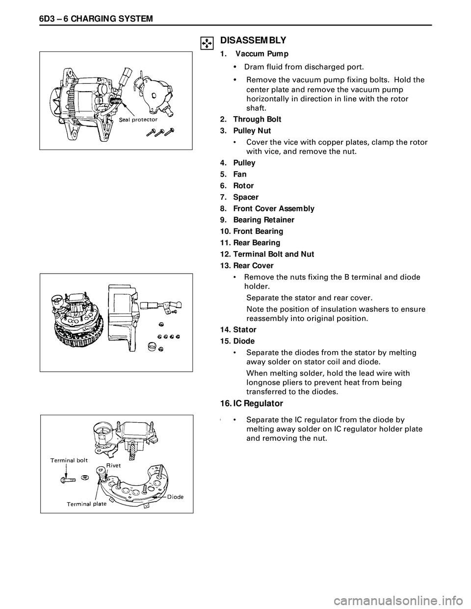
1. Vaccum Pump
¥Dram fluid from discharged port.
¥Remove the vacuum pump fixing bolts. Hold the
center plate and remove the vacuum pump
horizontally in direction in line with the rotor
shaft.
2. Through Bolt
3. Pulley Nut
¥ Cover the vice with copper plates, clamp the rotor
with vice, and remove the nut.
4. Pulley
5. Fan
6. Rotor
7. Spacer
8. Front Cover Assembly
9. Bearing Retainer
10. Front Bearing
11. Rear Bearing
12. Terminal Bolt and Nut
13. Rear Cover
¥ Remove the nuts fixing the B terminal and diode
holder.
Separate the stator and rear cover.
Note the position of insulation washers to ensure
reassembly into original position.
14. Stator
15. Diode
¥ Separate the diodes from the stator by melting
away solder on stator coil and diode.
When melting solder, hold the lead wire with
longnose pliers to prevent heat from being
transferred to the diodes.
16. IC Regulator
¥¥ Separate the IC regulator from the diode by
melting away solder on IC regulator holder plate
and removing the nut.
Page 1713 of 3573
CHARGING SYSTEM 6D3 Ð 7
17. Brush Holder Assembly
¥ Remove the serrated bolts and melt away solder on
IC regulator.
¥ Do not remove the serrated bolts unless the
replacement of brush or condenser.
To install, follow the removal steps in the reverse
order.
INSPECTION AND REPAIR
Repair or replace necessary parts if extreme wear or
damage is found during inspection.
ROTOR ASSEMBLY
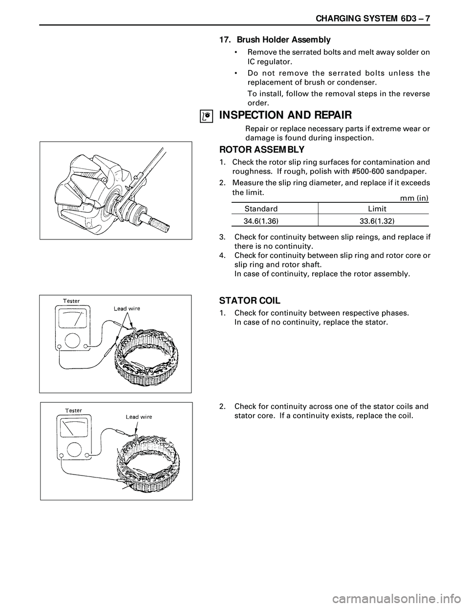
1. Check the rotor slip ring surfaces for contamination and
roughness. If rough, polish with #500-600 sandpaper.
2. Measure the slip ring diameter, and replace if it exceeds
the limit.
3. Check for continuity between slip reings, and replace if
there is no continuity.
4. Check for continuity between slip ring and rotor core or
slip ring and rotor shaft.
In case of continuity, replace the rotor assembly.
STATOR COIL
1. Check for continuity between respective phases.
In case of no continuity, replace the stator.
2. Check for continuity across one of the stator coils and
stator core. If a continuity exists, replace the coil.
34.6(1.36) 33.6(1.32)mm (in)
Standard Limit
Page 1714 of 3573
6D3 Ð 8 CHARGING SYSTEM
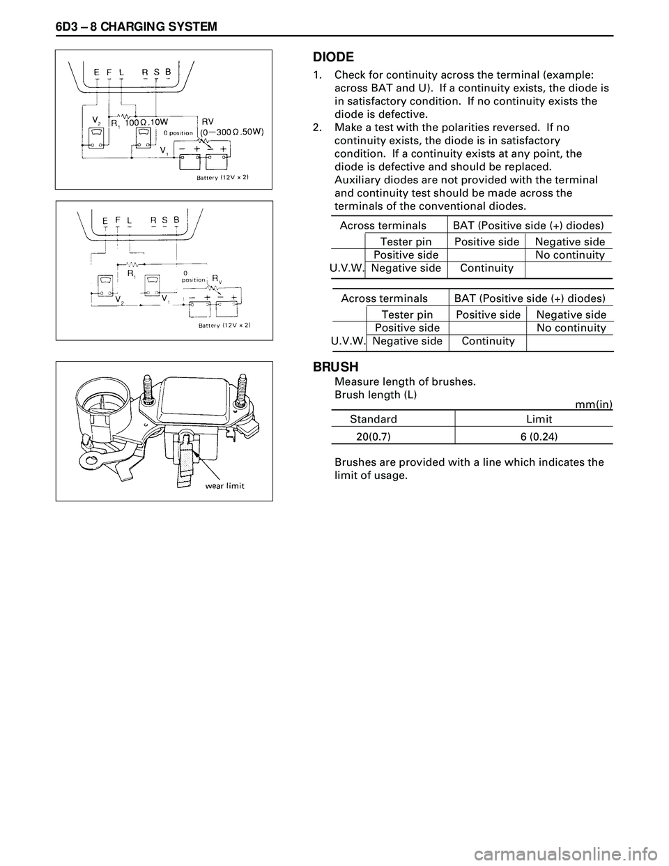
DIODE
1. Check for continuity across the terminal (example:
across BAT and U). If a continuity exists, the diode is
in satisfactory condition. If no continuity exists the
diode is defective.
2. Make a test with the polarities reversed. If no
continuity exists, the diode is in satisfactory
condition. If a continuity exists at any point, the
diode is defective and should be replaced.
Auxiliary diodes are not provided with the terminal
and continuity test should be made across the
terminals of the conventional diodes.
BRUSH
Measure length of brushes.
Brush length (L)
Across terminals BAT (Positive side (+) diodes)
Tester pin
Positive side
Negative sidePositive side
ContinuityNegative side
No continuity
U.V.W.
Across terminals BAT (Positive side (+) diodes)
Tester pin
Positive side
Negative sidePositive side
ContinuityNegative side
No continuity
U.V.W.
20(0.7) 6 (0.24)mm(in)
Standard Limit
Brushes are provided with a line which indicates the
limit of usage.