Page 2197 of 3573
7A±43 AUTOMATIC TRANSMISSION (4L30±E)
Rear Oil Seal (Extension Housing)
Removal
1. Remove transfer case assembly from the vehicle.
Refer to Transfer Case in Drive Line/Axle section.
2. Remove rear oil seal from transmission extension
housing.
241RW005
Installation
1. Use 5±8840±2282±0 (J±36797) extension housing
oil seal installer, and install the rear oil seal to the
transmission extension housing.
2. Install the transfer case assembly to the vehicle.
Refer to Transfer Case in Drive Line/Axle section.
Transmission (4L30±E)
Disassembly
NOTE: During the disassembly and reassembly, perform
the following:
�Wash each part thoroughly, and blow air through each
oil passage and groove to eliminate blockage.
�Seal rings, roll pins, and gaskets should be replaced.
�When assembling the components, apply
DEXRON)±III Automatic Transmission Fluid (ATF)
to each seal, rotating part, and sliding part.
�Do not dip part facings, such as clutch or brake drive
plates, in cleaner when washing it.
Also, always coat parts with new ATF two or three
times after cleaning with solvent.
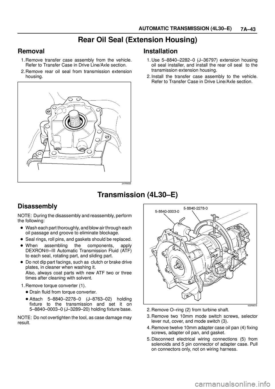
1. Remove torque converter (1).
�Drain fluid from torque converter.
�Attach 5±8840±2278±0 (J±8763±02) holding
fixture to the transmission and set it on
5±8840±0003±0 (J±3289±20) holding fixture base.
NOTE: Do not overtighten the tool, as case damage may
result.
420RW019
2. Remove O±ring (2) from turbine shaft.
3. Remove two 10mm mode switch screws, selector
lever nut, cover, and mode switch (3).
4. Remove twelve 10mm adapter case oil pan (4) fixing
screws, adapter oil pan, and gasket.
5. Disconnect electrical wiring connections (5) from
solenoids and 5 pin connector of adapter case. Pull
on connectors only, not on wiring harness.
Page 2267 of 3573
7A1±22
TRANSMISSION CONTROL SYSTEM (4L30±E)
connection or loose wiring. Terminals and grounds should
always be the prime suspect. Intermittents rarely occur
inside sophisticated electronic components such as the
PCM.
Use the DTC information to understand which wires and
sensors are involved.
When an intermittent problem is encountered, check
suspect circuits for:
1. Poor terminal to wire connection.
2. Terminals not fully seated in the connector body
(backed out).
3. Improperly formed or damaged terminals.
4. Loose, dirty, or corroded ground connections:
HINT: Any time you have an intermittent in more than
one circuit, check whether the circuits share a
common ground connection.
5. Pinched or damaged wires.
6. Electro±Magnetic Interference (EMI):
HINT: Check that all wires are properly routed away
from spark plug wires, distributor wires, coil, and
generator. Also check for improperly installed
electrical options, such as lights, 2±way radios, etc.Use the F3 SNAPSHOT mode of the Tech2 to help isolate
the cause of an intermittent fault. The snapshot mode will
record information before and after the problem occurs.
Set the snapshot to ªtriggerº on the suspect DTC. If you
notice the reported symptom during the test drive, trigger
the snapshot manually.
After the snapshot has been triggered, command the
Tech2 to play back the flow of data recorded from each of
the various sensors. Signs of an intermittent fault in a
sensor circuit are sudden unexplainable jump in data
values out of the normal range.
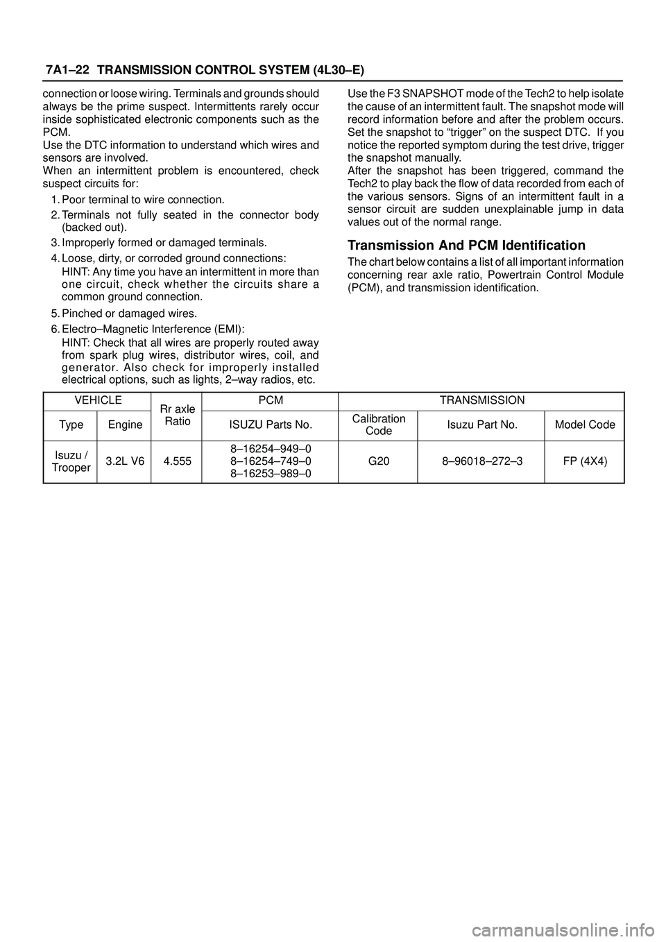
Transmission And PCM Identification
The chart below contains a list of all important information
concerning rear axle ratio, Powertrain Control Module
(PCM), and transmission identification.
VEHICLE
Rr axlePCMTRANSMISSION
TypeEngine
Rr axle
RatioISUZU Parts No.Calibration
CodeIsuzu Part No.Model Code
Isuzu /
Trooper3.2L V64.555
8±16254±949±0
8±16254±749±0
8±16253±989±0
G208±96018±272±3FP (4X4)
Page 2297 of 3573
7A1±52
TRANSMISSION CONTROL SYSTEM (4L30±E)
Conditions For Clearing The DTC/CHECK
TRANS Lamp
�The PCM will turn ªoffº the CHECK TRANS Lamp
after three consecutive ignition cycles without a
failure reported.
�The DTC can be cleared from PCM memory by using
a scan tool.
�The DTC can also be cleared from memory when the
vehicle has made 40 warmup cycles without a failure
reported.
�The PCM will cancel the DTC Actions Taken items
when the fault conditions no longer exist and the
ignition is cycles ªoffº long enough to power down the
PCM.
Diagnostic Aids
�Check for intermittent output speed sensor circuit
problems.
�Check for possible incorrect calibration. (PCM part
No., tire specification, and rear axle ratio)
Test Description
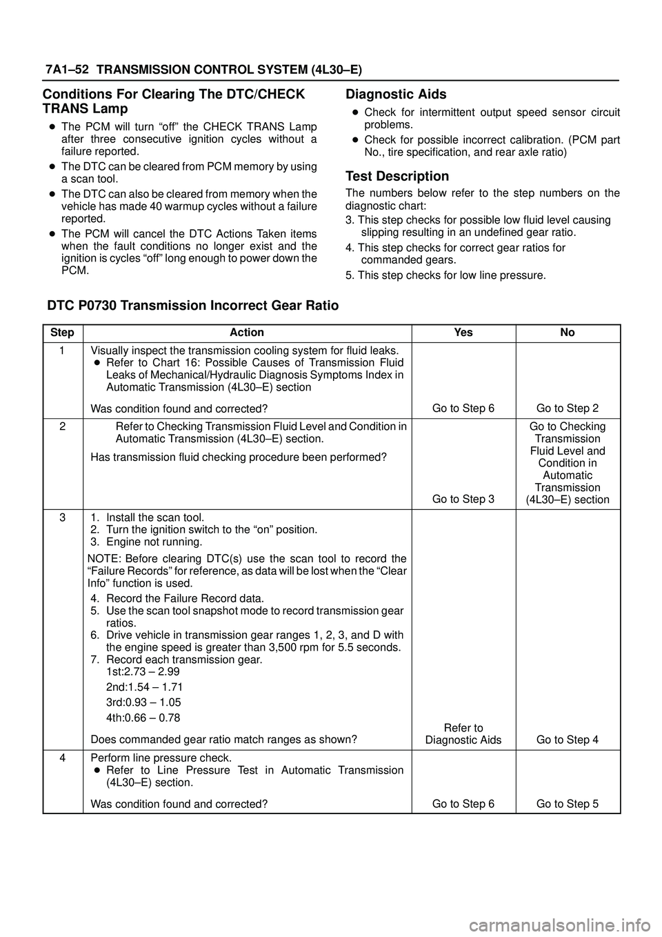
The numbers below refer to the step numbers on the
diagnostic chart:
3. This step checks for possible low fluid level causing
slipping resulting in an undefined gear ratio.
4. This step checks for correct gear ratios for
commanded gears.
5. This step checks for low line pressure.
DTC P0730 Transmission Incorrect Gear Ratio
StepActionYe sNo
1Visually inspect the transmission cooling system for fluid leaks.
�Refer to Chart 16: Possible Causes of Transmission Fluid
Leaks of Mechanical/Hydraulic Diagnosis Symptoms Index in
Automatic Transmission (4L30±E) section
Was condition found and corrected?
Go to Step 6Go to Step 2
2Refer to Checking Transmission Fluid Level and Condition in
Automatic Transmission (4L30±E) section.
Has transmission fluid checking procedure been performed?
Go to Step 3
Go to Checking
Transmission
Fluid Level and
Condition in
Automatic
Transmission
(4L30±E) section
31. Install the scan tool.
2. Turn the ignition switch to the ªonº position.
3. Engine not running.
NOTE: Before clearing DTC(s) use the scan tool to record the
ªFailure Recordsº for reference, as data will be lost when the ªClear
Infoº function is used.
4. Record the Failure Record data.
5. Use the scan tool snapshot mode to record transmission gear
ratios.
6. Drive vehicle in transmission gear ranges 1, 2, 3, and D with
the engine speed is greater than 3,500 rpm for 5.5 seconds.
7. Record each transmission gear.
1st:2.73 ± 2.99
2nd:1.54 ± 1.71
3rd:0.93 ± 1.05
4th:0.66 ± 0.78
Does commanded gear ratio match ranges as shown?
Refer to
Diagnostic Aids
Go to Step 4
4Perform line pressure check.
�Refer to Line Pressure Test in Automatic Transmission
(4L30±E) section.
Was condition found and corrected?
Go to Step 6Go to Step 5
Page 2329 of 3573
MANUAL TRANSMISSION7B±11
220RW119
Legend
(1) Pressure Plate Assembly
(2) Release Bearing
(3) Wedge Collar
30. Remove the transmission retaining nuts and bolts.
31. Remove the transmission assembly with transfer
case from the vehicle.
NOTE: Remove the transfer case from the transmission
assembly if the transmission disassembly required.
Refer to Transfer Case in Drive Line/Axle section.
Installation
1. Apply a thin coat of molybdenum disulfide grease to
the top gear shaft spline.
2. Slowly operate the transmission jack until the front of
transmission is aligned with the rear of the engine.
The slope of the engine and the transmission must be
the same.
3. Align the top gear shaft spline with the clutch driven
plate spline.
220RS005
4. Install the transmission to the engine.
Tighten the transmission retaining nuts and bolts.
Page 2335 of 3573
MANUAL TRANSMISSION7B±17
Rear Oil Seal (Transfer Adapter)
Removal
1. Remove the transfer case assembly from the vehicle.
Refer to Transfer Case in Drive Line/Axle section.
2. Remove the rear oil seal from the transfer adapter.
220RW090
Installation
1. Use 5±8840±2558±0 (J±42802) transfer adapter oil
seal installer, and install the rear oil seal to the transfer
adapter.
2. Apply grease to the oil seal lip.
3. Install the transfer case assembly to the vehicle.
Refer to Transfer Case in Drive Line/Axle section.
220RW115
Page 3219 of 3573
8F±24BODY STRUCTURE
Body Mounting
Parts Location
E02RW006
Removal (No.1 ± No. 2)
1. Remove the front bumper.
2. Jack up the vehicle by the frame.
3. Support the front side sill and rear axle with stands.
Further, support the front jack up point with a jack.
Page 3220 of 3573
8F±25 BODY STRUCTURE
620RS001
420RS001
545RS001
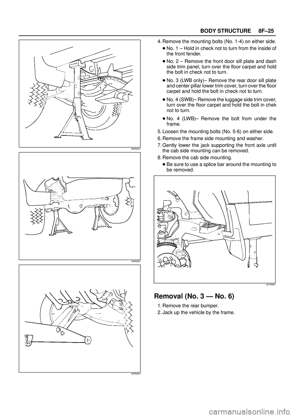
4. Remove the mounting bolts (No. 1-4) on either side.
�No. 1 ± Hold in check not to turn from the inside of
the front fender.
�No. 2 ± Remove the front door sill plate and dash
side trim panel, turn over the floor carpet and hold
the bolt in check not to turn.
�No. 3 (LWB only)± Remove the rear door sill plate
and center pillar lower trim cover, turn over the floor
carpet and hold the bolt in check not to turn.
�No. 4 (SWB)± Remove the luggage side trim cover,
turn over the floor carpet and hold the bolt in chek
not to turn.
�No. 4 (LWB)± Remove the bolt from under the
frame.
5. Loosen the mounting bolts (No. 5-6) on either side.
6. Remove the frame side mounting and washer.
7. Gently lower the jack supporting the front axle until
the cab side mounting can be removed.
8. Remove the cab side mounting.
�Be sure to use a splice bar around the mounting to
be removed.
501RS001
Removal (No. 3 Ð No. 6)
1. Remove the rear bumper.
2. Jack up the vehicle by the frame.
Page 3221 of 3573
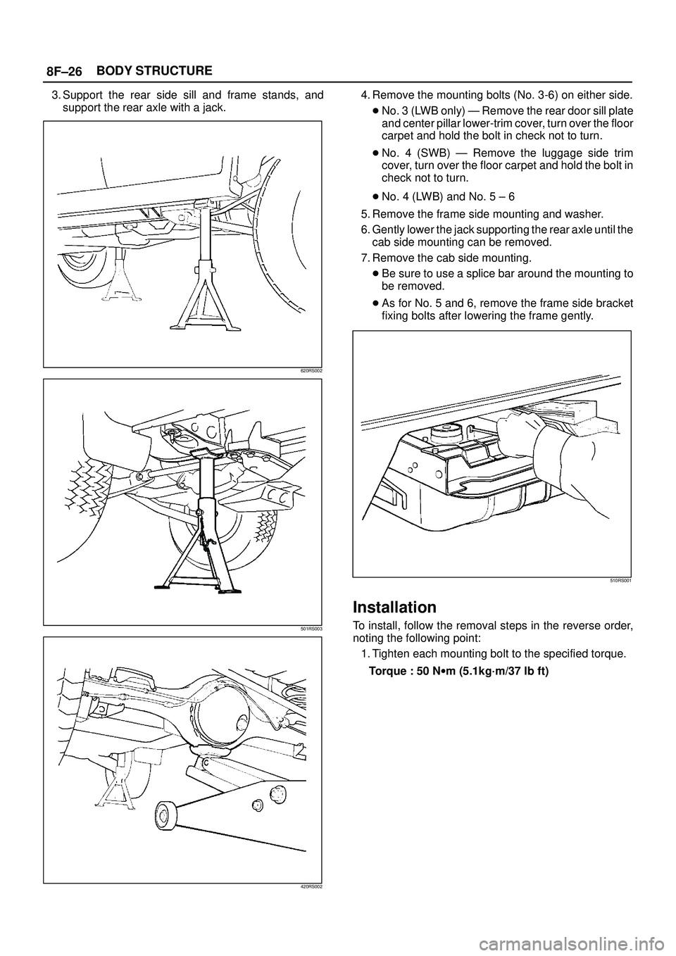
8F±26BODY STRUCTURE
3. Support the rear side sill and frame stands, and
support the rear axle with a jack.
620RS002
501RS003
420RS002
4. Remove the mounting bolts (No. 3-6) on either side.
�No. 3 (LWB only) Ð Remove the rear door sill plate
and center pillar lower-trim cover, turn over the floor
carpet and hold the bolt in check not to turn.
�No. 4 (SWB) Ð Remove the luggage side trim
cover, turn over the floor carpet and hold the bolt in
check not to turn.
�No. 4 (LWB) and No. 5 ± 6
5. Remove the frame side mounting and washer.
6. Gently lower the jack supporting the rear axle until the
cab side mounting can be removed.
7. Remove the cab side mounting.
�Be sure to use a splice bar around the mounting to
be removed.
�As for No. 5 and 6, remove the frame side bracket
fixing bolts after lowering the frame gently.
510RS001
Installation
To install, follow the removal steps in the reverse order,
noting the following point:
1. Tighten each mounting bolt to the specified torque.
Torque : 50 Nwm (5.1kg´m/37 lb ft)