Page 904 of 3573

5C – 26 POWER ASSISTED BRAKE SYSTEM
REMOVAL
Preparation:
1) Raise the vehicle and support it with suitable
safety stands.
2) Remove wheel and tire assembly.
3) Clean dirt, grease, and other foreign material off
the hose fittings at both ends.
Front/Rear Caliper Brake Hose
1. Brake Pipe
2. Clip
3. Bolt and Gasket
4. Hose
Rear Axle Brake Hose
1. Brake Pipe
2. Clip
3. Brake Pipe
4. Bolt
5. Hose
INSTALLATION
To install, follow the removal steps in the reverse
order, noting the following points. After installing the
brake hoses, bleed brakes as described in this
section.
Front/Rear Caliper Brake Hose
1. Tighten the brake pipes to the specified torque.
Brake Pipe Torque N·m(kg·m/lb·ft)
16 (1.6 / 12)
2. Tighten the bolt to the specified torque.
Bolt Torque N·m(kg·m/lb·ft)
35 (3.5 / 26)
NOTE:
•Always use new copper gaskets.
•Be sure to put the hooked edge of the flexible
hose end into the anti-rotation cavity.
Rear Axle Brake Hose
1. Tighten the brake pipes to the specified torque.
Brake Pipe Torque N·m(kg·m/lb·ft)
16 (1.6 / 12)
2. Tighten the bolt to the specified torque.
Bolt Torque N·m(kg·cm/lb·in)
13 (130 / 113)
Page 908 of 3573
5C – 30 POWER ASSISTED BRAKE SYSTEM
LOAD SENSING PROPORTIONING VALVE (LSPV)
(FOR EUROPE AND SOUTH AFRICA)
to rear wheel cylinder
from front master cylinder
from rear master cylinder
Structure and Operation
The following is an explanation of the structure and
operation of the linkage type load sensing device.
This device controls the fluid pressure to the rear
brakes in accordance with changes in rear axle load
(vertical displacements of the rear axle springs).
•Structure
This device consists of a load sensing lever and a
valve.
The valve is mounted through a bracket to the
frame. One end of the load sensing lever is fixed
to the valve at the frame and the other end to the
rear axle housing through a spring.
F05RW003
Page 910 of 3573

5C – 32 POWER ASSISTED BRAKE SYSTEM
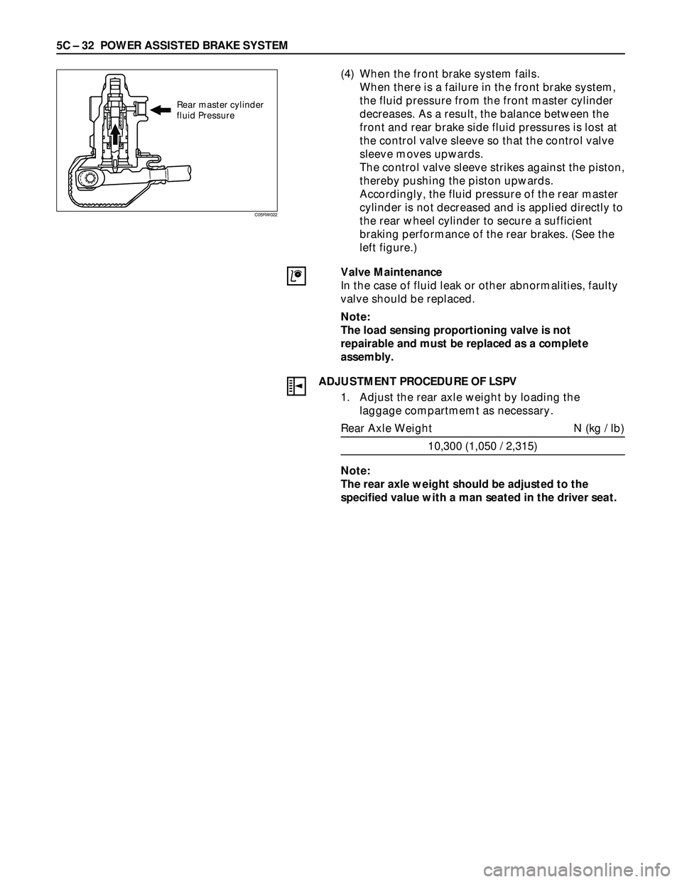
(4) When the front brake system fails.
When there is a failure in the front brake system,
the fluid pressure from the front master cylinder
decreases. As a result, the balance between the
front and rear brake side fluid pressures is lost at
the control valve sleeve so that the control valve
sleeve moves upwards.
The control valve sleeve strikes against the piston,
thereby pushing the piston upwards.
Accordingly, the fluid pressure of the rear master
cylinder is not decreased and is applied directly to
the rear wheel cylinder to secure a sufficient
braking performance of the rear brakes. (See the
left figure.)
Valve Maintenance
In the case of fluid leak or other abnormalities, faulty
valve should be replaced.
Note:
The load sensing proportioning valve is not
repairable and must be replaced as a complete
assembly.
ADJUSTMENT PROCEDURE OF LSPV
1. Adjust the rear axle weight by loading the
laggage compartmemt as necessary.
Rear Axle Weight N (kg / lb)
10,300 (1,050 / 2,315)
Note:
The rear axle weight should be adjusted to the
specified value with a man seated in the driver seat.
Rear master cylinder
fluid Pressure
C05RW022
Page 1004 of 3573

6A±48
ENGINE MECHANICAL
Engine Assembly
Removal
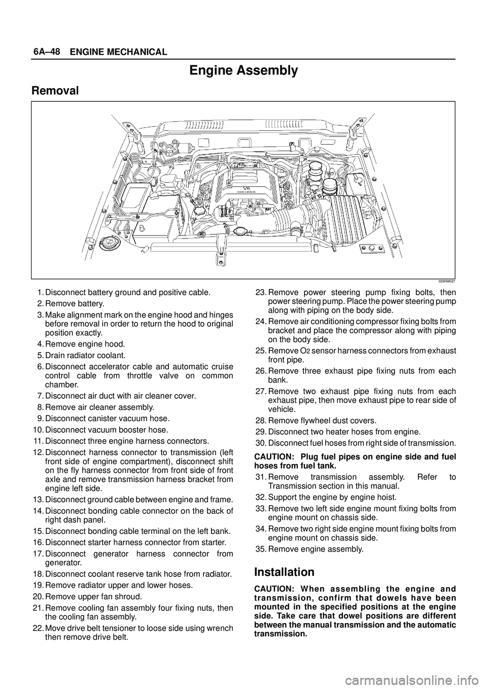
035RW027
1. Disconnect battery ground and positive cable.
2. Remove battery.
3. Make alignment mark on the engine hood and hinges
before removal in order to return the hood to original
position exactly.
4. Remove engine hood.
5. Drain radiator coolant.
6. Disconnect accelerator cable and automatic cruise
control cable from throttle valve on common
chamber.
7. Disconnect air duct with air cleaner cover.
8. Remove air cleaner assembly.
9. Disconnect canister vacuum hose.
10. Disconnect vacuum booster hose.
11. Disconnect three engine harness connectors.
12. Disconnect harness connector to transmission (left
front side of engine compartment), disconnect shift
on the fly harness connector from front side of front
axle and remove transmission harness bracket from
engine left side.
13. Disconnect ground cable between engine and frame.
14. Disconnect bonding cable connector on the back of
right dash panel.
15. Disconnect bonding cable terminal on the left bank.
16. Disconnect starter harness connector from starter.
17. Disconnect generator harness connector from
generator.
18. Disconnect coolant reserve tank hose from radiator.
19. Remove radiator upper and lower hoses.
20. Remove upper fan shroud.
21. Remove cooling fan assembly four fixing nuts, then
the cooling fan assembly.
22. Move drive belt tensioner to loose side using wrench
then remove drive belt.23. Remove power steering pump fixing bolts, then
power steering pump. Place the power steering pump
along with piping on the body side.
24. Remove air conditioning compressor fixing bolts from
bracket and place the compressor along with piping
on the body side.
25. Remove O
2 sensor harness connectors from exhaust
front pipe.
26. Remove three exhaust pipe fixing nuts from each
bank.
27. Remove two exhaust pipe fixing nuts from each
exhaust pipe, then move exhaust pipe to rear side of
vehicle.
28. Remove flywheel dust covers.
29. Disconnect two heater hoses from engine.
30. Disconnect fuel hoses from right side of transmission.
CAUTION: Plug fuel pipes on engine side and fuel
hoses from fuel tank.
31. Remove transmission assembly. Refer to
Transmission section in this manual.
32. Support the engine by engine hoist.
33. Remove two left side engine mount fixing bolts from
engine mount on chassis side.
34. Remove two right side engine mount fixing bolts from
engine mount on chassis side.
35. Remove engine assembly.
Installation
CAUTION: W h e n assembling the engine and
transmission, confirm that dowels have been
mounted in the specified positions at the engine
side. Take care that dowel positions are different
between the manual transmission and the automatic
transmission.
Page 1149 of 3573
6E±32
ENGINE DRIVEABILITY AND EMISSIONS
Undercarriage Component Locator
F00RW040
Undercarriage Component Locator Table (Automatic Transmission)
Number
NameLocation
1Fuel Pump AssemblyInstalled in the top of the fuel tank
2Fuel Gauge UnitInstalled in the front edge of the fuel tank, on
the right side
3Fuel FilterLocated along the inside of the right frame rail,
ahead of the rear axle
4Vehicle Speed Sensor (VSS)2WD: Protrudes from the transmission
housing, just ahead of the propeller shaft.
4WD: Protrudes from the rear output shaft
housing of the transfer case.
5Heated Oxygen Sensor (Bank 1, HO2S 1)Threaded into the exhaust pipe ahead of the
right-hand catalytic converter
6Heated Oxygen Sensor (Bank 2, HO2S 1)Threaded into the exhaust pipe ahead the
left-hand catalytic converter
Page 1150 of 3573
6E±33 ENGINE DRIVEABILITY AND EMISSIONS
Undercarriage Component Locator Table (Manual Transmission)
Number
NameLocation
1Fuel Pump AssemblyInstalled in the top of the fuel tank
2Fuel Gauge UnitInstalled in the front edge of the right frame
rail, ahead of the rear axle
3Fuel FilterLocated along the inside of the right frame rail,
ahead of the rear axle
4Vehicle Speed Sensor (VSS)2WD: Protrudes from the transmission
housing, just ahead of the propeller shaft.
4WD: Protrudes from the rear output shaft
housing of the transfer case.
5Heated Oxygen Sensor (Bank 1, HO2S 1)Threaded into the exhaust pipe ahead of the
right-hand catalytic converter
6Heated Oxygen Sensor (Bank 2, HO2S 1)Threaded into the exhaust pipe ahead of the
left-hand catalytic converter
Fuse and Relay Panel (Underhood Electrical Center)
TS23336
Page 2178 of 3573

7A±24
AUTOMATIC TRANSMISSION (4L30±E)
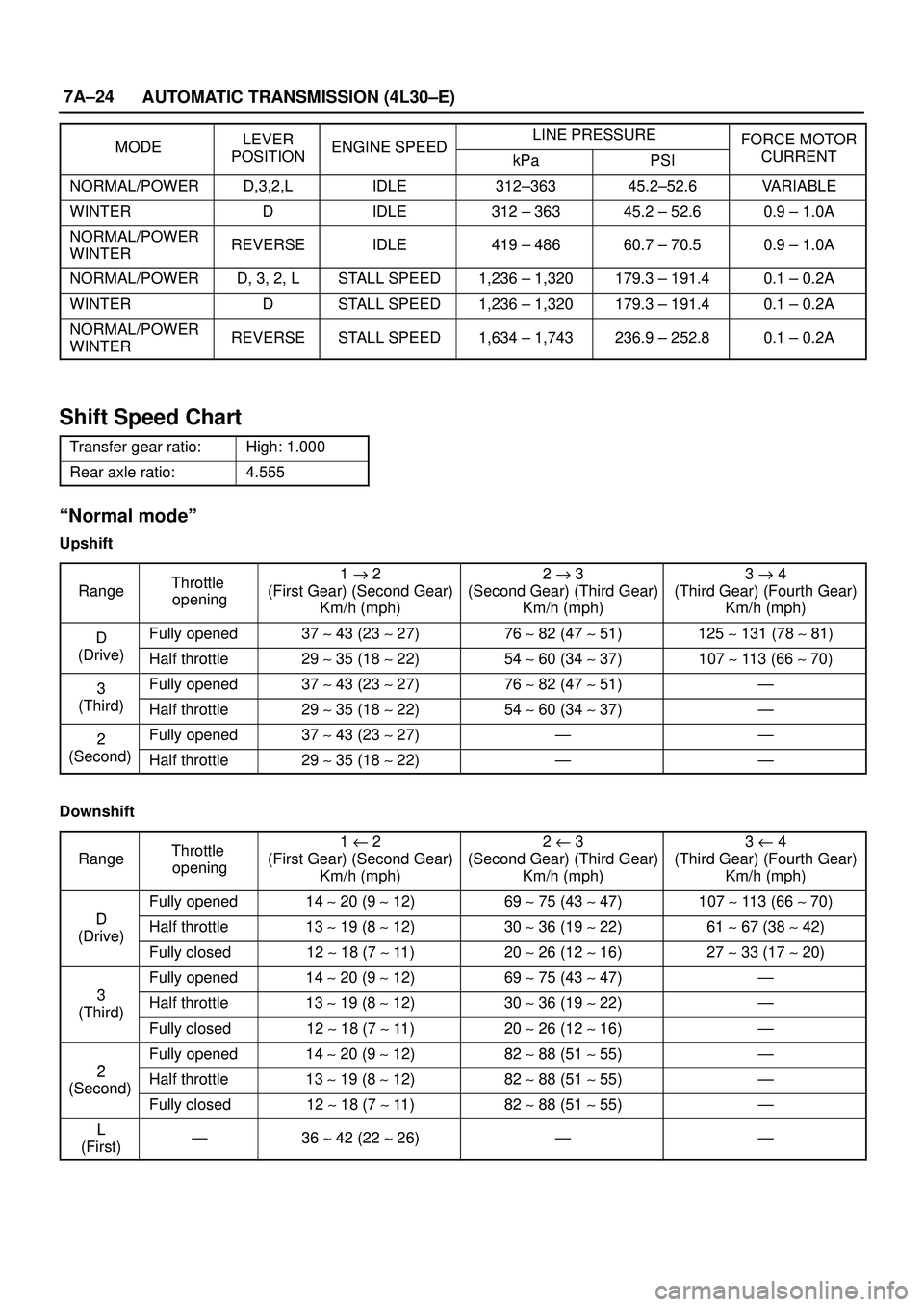
MODELEVERENGINE SPEEDLINE PRESSUREFORCE MOTORMODEPOSITIONENGINE SPEEDkPaPSICURRENT
NORMAL/POWERD,3,2,LIDLE312±36345.2±52.6VARIABLE
WINTERDIDLE312 ± 36345.2 ± 52.60.9 ± 1.0A
NORMAL/POWER
WINTERREVERSEIDLE419 ± 48660.7 ± 70.50.9 ± 1.0A
NORMAL/POWERD, 3, 2, LSTALL SPEED1,236 ± 1,320179.3 ± 191.40.1 ± 0.2A
WINTERDSTALL SPEED1,236 ± 1,320179.3 ± 191.40.1 ± 0.2A
NORMAL/POWER
WINTERREVERSESTALL SPEED1,634 ± 1,743236.9 ± 252.80.1 ± 0.2A
Shift Speed Chart
Transfer gear ratio:High: 1.000
Rear axle ratio:4.555
ªNormal modeº
Upshift
Range
Throttle
opening1 " 2
(First Gear) (Second Gear)
Km/h (mph)2 " 3
(Second Gear) (Third Gear)
Km/h (mph)3 " 4
(Third Gear) (Fourth Gear)
Km/h (mph)
DFully opened37 ~ 43 (23 ~ 27)76 ~ 82 (47 ~ 51)125 ~ 131 (78 ~ 81)
(Drive)Half throttle29 ~ 35 (18 ~ 22)54 ~ 60 (34 ~ 37)107 ~ 113 (66 ~ 70)
3Fully opened37 ~ 43 (23 ~ 27)76 ~ 82 (47 ~ 51)Ð
(Third)Half throttle29 ~ 35 (18 ~ 22)54 ~ 60 (34 ~ 37)Ð
2Fully opened37 ~ 43 (23 ~ 27)ÐÐ
(Second)Half throttle29 ~ 35 (18 ~ 22)ÐÐ
Downshift
Range
Throttle
opening1 u 2
(First Gear) (Second Gear)
Km/h (mph)2 u 3
(Second Gear) (Third Gear)
Km/h (mph)3 u 4
(Third Gear) (Fourth Gear)
Km/h (mph)
D
Fully opened14 ~ 20 (9 ~ 12)69 ~ 75 (43 ~ 47)107 ~ 113 (66 ~ 70)
D
(Drive)Half throttle13 ~ 19 (8 ~ 12)30 ~ 36 (19 ~ 22)61 ~ 67 (38 ~ 42)(Drive)
Fully closed12 ~ 18 (7 ~ 11 )20 ~ 26 (12 ~ 16)27 ~ 33 (17 ~ 20)
3
Fully opened14 ~ 20 (9 ~ 12)69 ~ 75 (43 ~ 47)Ð
3
(Third)Half throttle13 ~ 19 (8 ~ 12)30 ~ 36 (19 ~ 22)Ð(Third)
Fully closed12 ~ 18 (7 ~ 11 )20 ~ 26 (12 ~ 16)Ð
2
Fully opened14 ~ 20 (9 ~ 12)82 ~ 88 (51 ~ 55)Ð
2
(Second)Half throttle13 ~ 19 (8 ~ 12)82 ~ 88 (51 ~ 55)Ð(Second)
Fully closed12 ~ 18 (7 ~ 11 )82 ~ 88 (51 ~ 55)Ð
L
(First)Ð36 ~ 42 (22 ~ 26)ÐÐ
Page 2180 of 3573
7A±26
AUTOMATIC TRANSMISSION (4L30±E)
Lockup Speed Chart
Transfer gear ratio:High: 1.000
Rear axle ratio:4.555
Lockup ONLockup OFF
D range Throttle
i6%
Mode2nd
Km/h
(mph)3rd
Km/h
(mph)4th
Km/h
(mph)2nd
Km/h
(mph)3rd
Km/h
(mph)4th
Km/h
(mph)
opening 6%Normal69 ~ 75
(43 ~ 47)63 ~ 69
(39 ~ 43)70 ~ 76
(43 ~ 47)64 ~ 70
(40 ~ 43)43 ~ 49
(27 ~ 30)65 ~ 71
(40 ~ 44)
Power69 ~ 75
(43 ~ 47)73 ~ 79
(45 ~ 49)73 ~ 79
(45 ~ 49)64 ~ 70
(40 ~ 43)65 ~ 71
(40 ~ 44)69 ~ 75
(43 ~ 47)