Page 3408 of 3573

EXTERIOR/INTERIOR TRIM8J±29
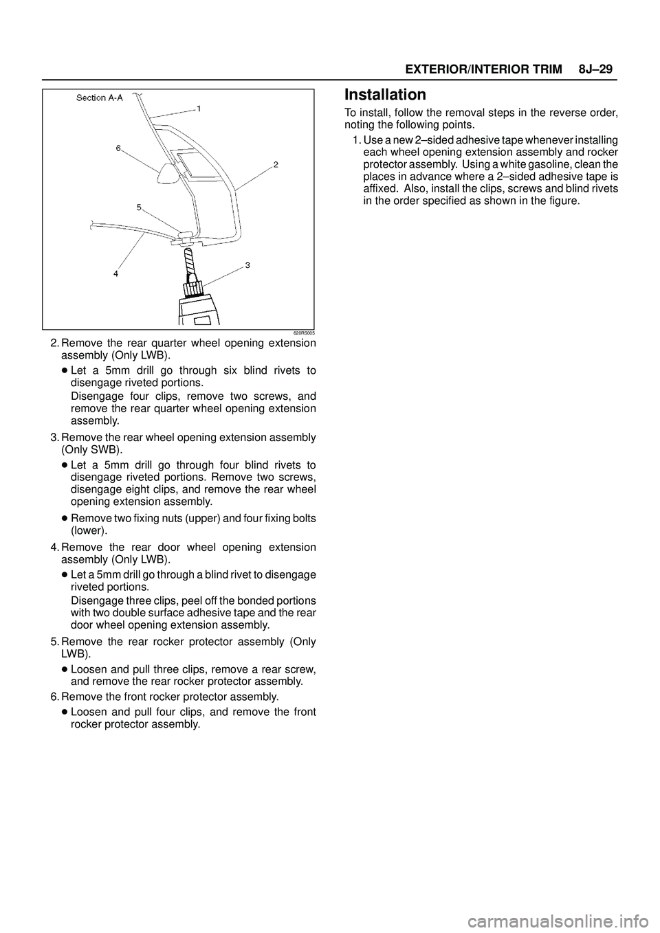
620RS005
2. Remove the rear quarter wheel opening extension
assembly (Only LWB).
�Let a 5mm drill go through six blind rivets to
disengage riveted portions.
Disengage four clips, remove two screws, and
remove the rear quarter wheel opening extension
assembly.
3. Remove the rear wheel opening extension assembly
(Only SWB).
�Let a 5mm drill go through four blind rivets to
disengage riveted portions. Remove two screws,
disengage eight clips, and remove the rear wheel
opening extension assembly.
�Remove two fixing nuts (upper) and four fixing bolts
(lower).
4. Remove the rear door wheel opening extension
assembly (Only LWB).
�Let a 5mm drill go through a blind rivet to disengage
riveted portions.
Disengage three clips, peel off the bonded portions
with two double surface adhesive tape and the rear
door wheel opening extension assembly.
5. Remove the rear rocker protector assembly (Only
LWB).
�Loosen and pull three clips, remove a rear screw,
and remove the rear rocker protector assembly.
6. Remove the front rocker protector assembly.
�Loosen and pull four clips, and remove the front
rocker protector assembly.
Installation
To install, follow the removal steps in the reverse order,
noting the following points.
1. Use a new 2±sided adhesive tape whenever installing
each wheel opening extension assembly and rocker
protector assembly. Using a white gasoline, clean the
places in advance where a 2±sided adhesive tape is
affixed. Also, install the clips, screws and blind rivets
in the order specified as shown in the figure.
Page 3418 of 3573

EXTERIOR/INTERIOR TRIM8J±39
Power Window System
General Description
The circuit consists of the starter switch, (door lock &)
power window switch for each of the front windows,
power window switch for rear windows and power window
motors.
When the starter switch is turned on, the battery voltage is
applied to each of the power window switches through the
circuit breaker and the power window relay on the circuit.
The ªDownº switch of the driver's power window switch
has a built-in function which can be operated by just
touching it.
Accordingly, the window will roll down automatically by
just setting the switch to the ªAUTOº position.
When the driver's power lock switch at the driver side is
depressed, the power source to the passenger's power
window switches are shut off. So, even if these switches
are operated, the power window motor will not operate.
Power Window Switch Removal and
Installation
Driver Seat Side
Removal
1. Disconnect the battery ground cable.
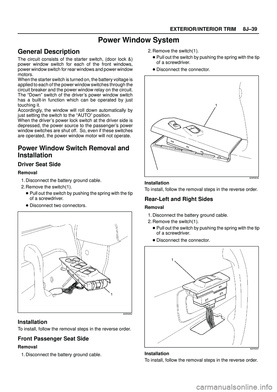
2. Remove the switch(1).
�Pull out the switch by pushing the spring with the tip
of a screwdriver.
�Disconnect two connectors.
825RS052
Installation
To install, follow the removal steps in the reverse order.
Front Passenger Seat Side
Removal
1. Disconnect the battery ground cable.2. Remove the switch(1).
�Pull out the switch by pushing the spring with the tip
of a screwdriver.
�Disconnect the connector.
825RW046
Installation
To install, follow the removal steps in the reverse order.
Rear-Left and Right Sides
Removal
1. Disconnect the battery ground cable.
2. Remove the switch(1).
�Pull out the switch by pushing the spring with the tip
of a screwdriver.
�Disconnect the connector.
825RS057
Installation
To install, follow the removal steps in the reverse order.
Page 3422 of 3573

9AÐ2 SEAT BELT SYSTEM
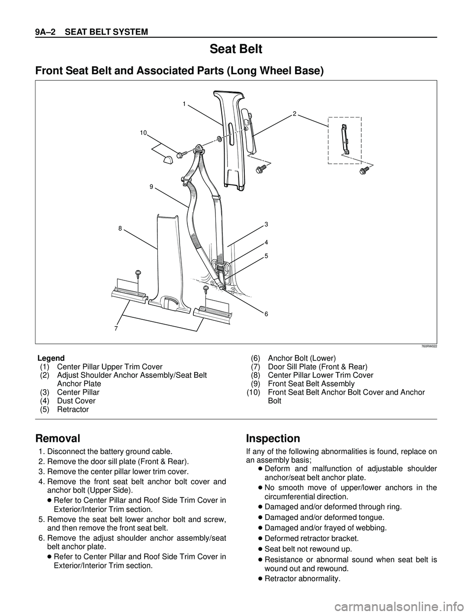
Legend
(1) Center Pillar Upper Trim Cover
(2) Adjust Shoulder Anchor Assembly/Seat Belt
Anchor Plate
(3) Center Pillar
(4) Dust Cover
(5) Retractor(6) Anchor Bolt (Lower)
(7) Door Sill Plate (Front & Rear)
(8) Center Pillar Lower Trim Cover
(9) Front Seat Belt Assembly
(10) Front Seat Belt Anchor Bolt Cover and Anchor
Bolt
Seat Belt
Front Seat Belt and Associated Parts (Long Wheel Base)
73
4
5
6 1
2
10
8
9
760RW022
Removal
1. Disconnect the battery ground cable.
2. Remove the door sill plate (Front & Rear).
3. Remove the center pillar lower trim cover.
4. Remove the front seat belt anchor bolt cover and
anchor bolt (Upper Side).
cRefer to Center Pillar and Roof Side Trim Cover in
Exterior/Interior Trim section.
5. Remove the seat belt lower anchor bolt and screw,
and then remove the front seat belt.
6. Remove the adjust shoulder anchor assembly/seat
belt anchor plate.
cRefer to Center Pillar and Roof Side Trim Cover in
Exterior/Interior Trim section.
Inspection
If any of the following abnormalities is found, replace on
an assembly basis;
cDeform and malfunction of adjustable shoulder
anchor/seat belt anchor plate.
cNo smooth move of upper/lower anchors in the
circumferential direction.
cDamaged and/or deformed through ring.
cDamaged and/or deformed tongue.
cDamaged and/or frayed of webbing.
cDeformed retractor bracket.
cSeat belt not rewound up.
cResistance or abnormal sound when seat belt is
wound out and rewound.
cRetractor abnormality.
Page 3485 of 3573

SUPPLEMENTAL RESTRAINT SYSTEM 9J±48
Passenger Air Bag Assembly
Service Precautions
WARNING: S A F E T Y P R ECAUTIONS MUST BE
FOLLOWED WHEN HANDLING A DEPLOYED AIR
BAG ASSEMBLY. AFTER DEPLOYMENT, THE AIR
BAG ASSEMBLY SURFACE MAY CONTAIN A SMALL
AMOUNT OF SODIUM HYDROXIDE, A BY±PRODUCT
OF THE DEPLOYMENT REACTION, THAT IS
IRRITATING TO THE SKIN AND EYES. MOST OF THE
POWER ON THE AIR BAG ASSEMBLY IS
HARMLESS. AS A PRECAUTION, WEAR GLOVES
AND SAFETY GLASSES WHEN HANDLING A
DEPLOYED AIR BAG ASSEMBLY, AND WASH YOUR
HANDS WITH MILD SOAP AND WATER
AFTERWARDS.
WARNING: W H E N C A R RY I N G A L I V E A I R B A G
ASSEMBLY, MAKE SURE THE BAG AND TRIM
COVER ARE POINTED AWAY FROM YOU. NEVER
CARRY AIR BAG ASSEMBLY BY THE WIRES OR
CONNECTOR ON THE UNDERSIDE OF MODULE. IN
THE CASE OF AN ACCIDENTAL DEPLOYMENT, THE
BAG WILL THEN DEPLOY WITH MINIMAL CHANCE
OF INJURY. WHEN PLACING ALIVE AIR BAG
ASSEMBLY ON A BENCH OR OTHER SURFACE,
ALWAYS FACE BAG AND RIM COVER UP, AWAY
FROM THE SURFACE. NEVER REST A STEERING
COLUMN ASSEMBLY ON THE STEERING WHEEL
WITH THE AIR BAG ASSEMBLY FACE DOWN AND
COLUMN VERTICAL. THIS IS NECESSARY SO THAT
A FREE SPACE IS PROVIDED TO ALLOW THE AIR
BAG ASSEMBLY TO EXPAND IN THE UNLIKELY
EVENT OF ACCIDENTAL DEPLOYMENT.
OTHERWISE, PERSONAL INJURY COULD RESULT.
NOTE: IN THE EVENT DEPLOYMENT HAS
OCCURRED, INSPECT COIL ASSEMBLY WIRE FOR
ANY SIGNS OF SCORCHING, MELTING OR ANY
OTHER DAMAGE DUE TO EXCESSIVE HEAT. IF THE
COIL HAS BEEN DAMAGED, REPLACE IT.
Removal
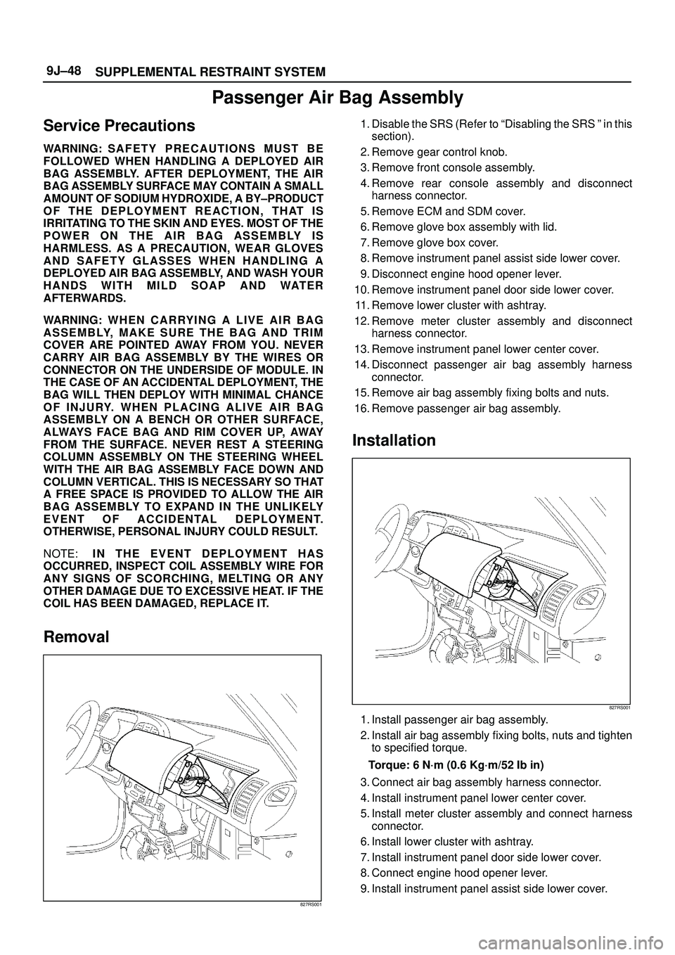
827RS001
1. Disable the SRS (Refer to ªDisabling the SRS º in this
section).
2. Remove gear control knob.
3. Remove front console assembly.
4. Remove rear console assembly and disconnect
harness connector.
5. Remove ECM and SDM cover.
6. Remove glove box assembly with lid.
7. Remove glove box cover.
8. Remove instrument panel assist side lower cover.
9. Disconnect engine hood opener lever.
10. Remove instrument panel door side lower cover.
11. Remove lower cluster with ashtray.
12. Remove meter cluster assembly and disconnect
harness connector.
13. Remove instrument panel lower center cover.
14. Disconnect passenger air bag assembly harness
connector.
15. Remove air bag assembly fixing bolts and nuts.
16. Remove passenger air bag assembly.
Installation
827RS001
1. Install passenger air bag assembly.
2. Install air bag assembly fixing bolts, nuts and tighten
to specified torque.
Torque: 6 N´m (0.6 Kg´m/52 Ib in)
3. Connect air bag assembly harness connector.
4. Install instrument panel lower center cover.
5. Install meter cluster assembly and connect harness
connector.
6. Install lower cluster with ashtray.
7. Install instrument panel door side lower cover.
8. Connect engine hood opener lever.
9. Install instrument panel assist side lower cover.