Page 2100 of 3573
6E±207 4JX1±TC ENGINE DRIVEABILITY AND EMISSIONS
damage, therefore, it is important to use care when
handling and testing electronic components.
NOTE: To prevent possible Electrostatic Discharge
damage, follow these guidelines:
�Do not touch the control module connector pins or
soldered components on the control module circuit
board.
�Do not open the replacement part package until the
part is ready to be installed.
�Before removing the part from the package, ground
the package to a known good ground on the vehicle.
�If the part has been handled while sliding across the
seat, or while sitting down from a standing position, or
while walking a distance, touch a known good ground
before installing the part.
NOTE: To prevent internal ECM damage, the ignition
must be in the ªOFFº position in order to disconnect or
reconnect power to the ECM (for example: battery cable,
ECM pigtail, ECM fuse, jumper cables, etc.).
IMPORTANT:When replacing the production ECM
with a service ECM, it is important to transfer the
broadcast code and production ECM number to the
service ECM label. This will allow positive identification of
ECM parts throughout the service life of the vehicle. Do
not record this information on the metal ECM cover.
IMPORTANT:The ignition should always be in the
ªOFFº position in order to install or remove the ECM
connectors.
Service of the ECM should normally consist of either re-
placement of the ECM. If the diagnostic procedures call
for the ECM to be replaced, the ECM should be checked
first to ensure it is the correct part. If it is, remove the
faulty ECM and install the new service ECM.
DTC P0601 indicates the check sum error.
Removal Procedure
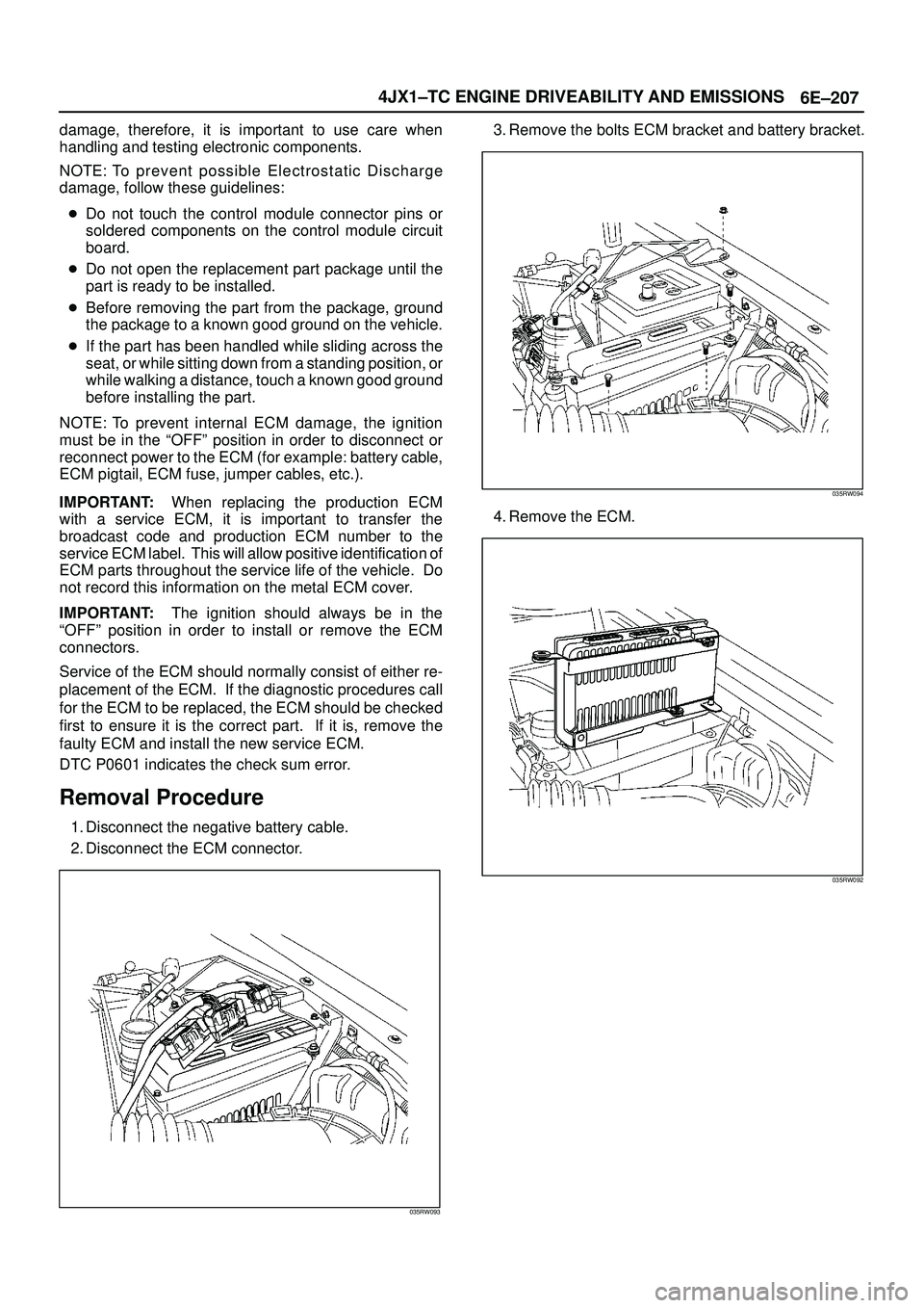
1. Disconnect the negative battery cable.
2. Disconnect the ECM connector.
035RW093
3. Remove the bolts ECM bracket and battery bracket.
035RW094
4. Remove the ECM.
035RW092
Page 2102 of 3573
6E±209 4JX1±TC ENGINE DRIVEABILITY AND EMISSIONS
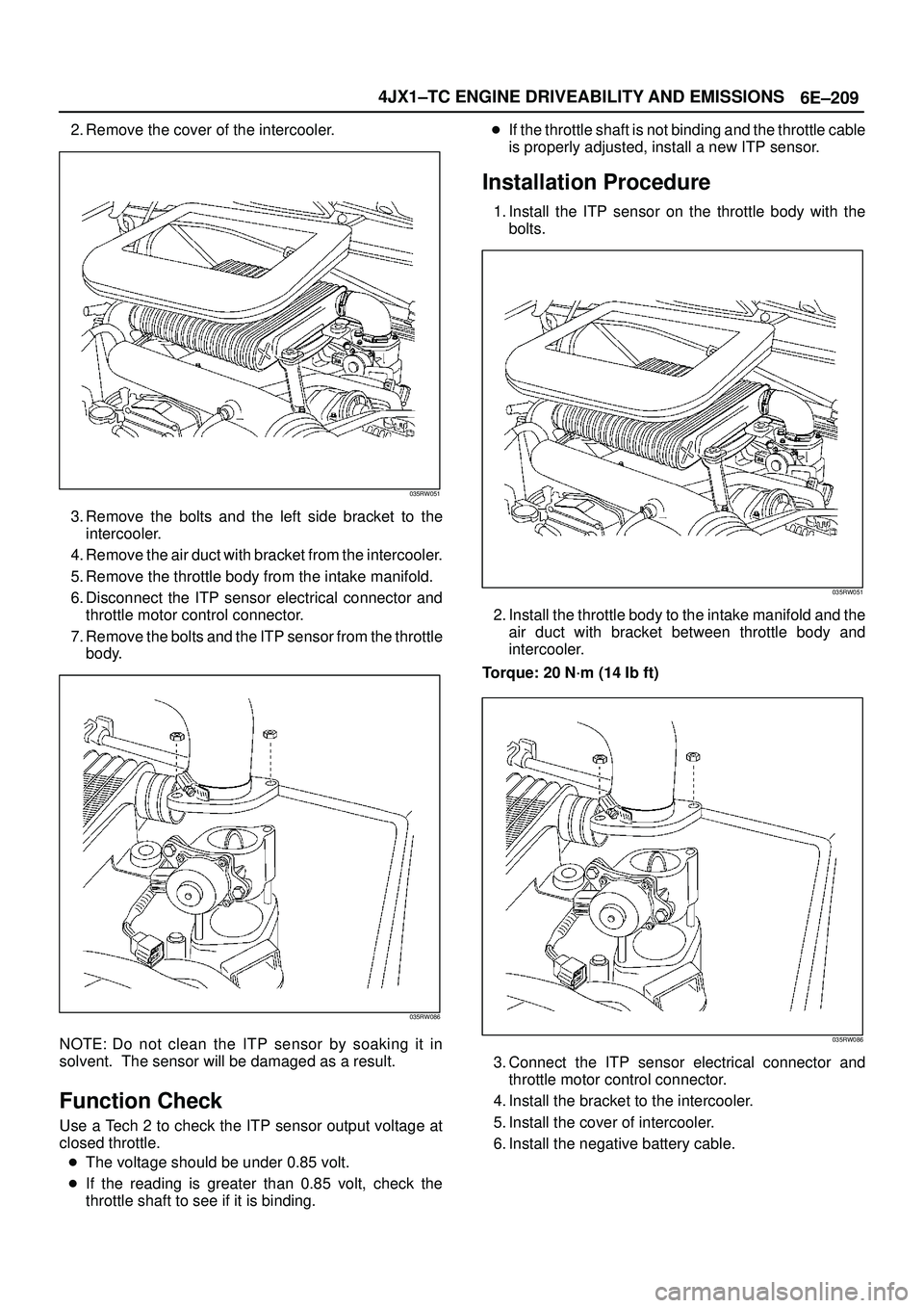
2. Remove the cover of the intercooler.
035RW051
3. Remove the bolts and the left side bracket to the
intercooler.
4. Remove the air duct with bracket from the intercooler.
5. Remove the throttle body from the intake manifold.
6. Disconnect the ITP sensor electrical connector and
throttle motor control connector.
7. Remove the bolts and the ITP sensor from the throttle
body.
035RW086
NOTE: Do not clean the ITP sensor by soaking it in
solvent. The sensor will be damaged as a result.
Function Check
Use a Tech 2 to check the ITP sensor output voltage at
closed throttle.
�The voltage should be under 0.85 volt.
�If the reading is greater than 0.85 volt, check the
throttle shaft to see if it is binding.�If the throttle shaft is not binding and the throttle cable
is properly adjusted, install a new ITP sensor.
Installation Procedure
1. Install the ITP sensor on the throttle body with the
bolts.
035RW051
2. Install the throttle body to the intake manifold and the
air duct with bracket between throttle body and
intercooler.
Torque: 20 N´m (14 Ib ft)
035RW086
3. Connect the ITP sensor electrical connector and
throttle motor control connector.
4. Install the bracket to the intercooler.
5. Install the cover of intercooler.
6. Install the negative battery cable.
Page 2103 of 3573
6E±210
4JX1±TC ENGINE DRIVEABILITY AND EMISSIONS
Vehicle Speed Sensor (VSS)
Removal Procedure
CAUTION: The VSS is located on the right side of
the transfer case just ahead of the rear propeller
shaft and very close to the exhaust pipes. Be sure
that the exhaust pipes are cool enough to touch
before trying to remove the VSS. If the pipes are hot,
you could be burned.
1. Disconnect the negative battery cable.
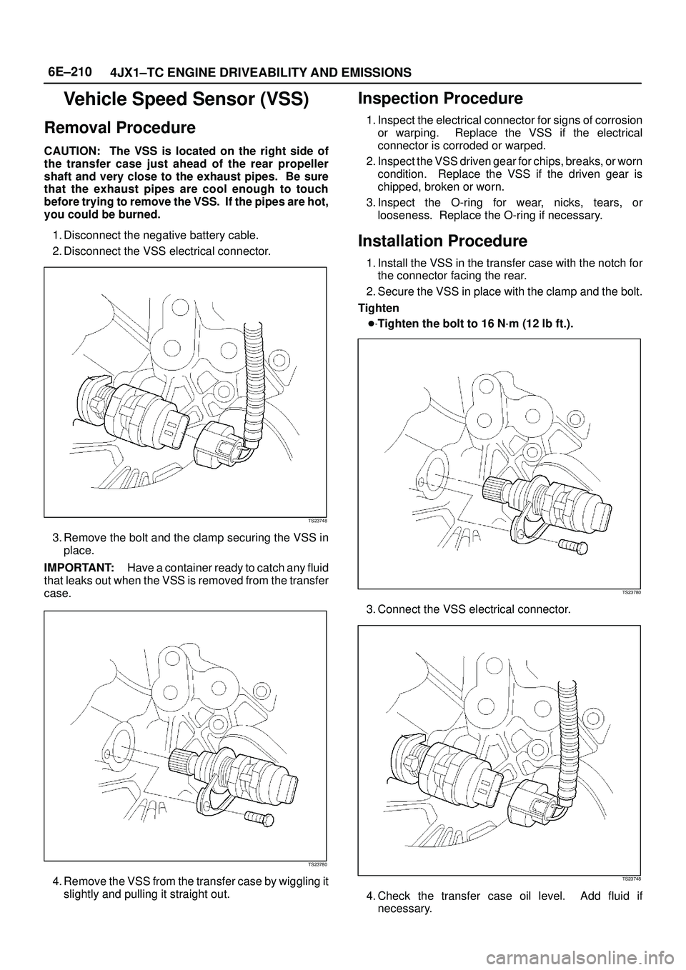
2. Disconnect the VSS electrical connector.
TS23748
3. Remove the bolt and the clamp securing the VSS in
place.
IMPORTANT:Have a container ready to catch any fluid
that leaks out when the VSS is removed from the transfer
case.
TS23780
4. Remove the VSS from the transfer case by wiggling it
slightly and pulling it straight out.
Inspection Procedure
1. Inspect the electrical connector for signs of corrosion
or warping. Replace the VSS if the electrical
connector is corroded or warped.
2. Inspect the VSS driven gear for chips, breaks, or worn
condition. Replace the VSS if the driven gear is
chipped, broken or worn.
3. Inspect the O-ring for wear, nicks, tears, or
looseness. Replace the O-ring if necessary.
Installation Procedure
1. Install the VSS in the transfer case with the notch for
the connector facing the rear.
2. Secure the VSS in place with the clamp and the bolt.
Tighten
�Tighten the bolt to 16 N´m (12 lb ft.).
TS23780
3. Connect the VSS electrical connector.
TS23748
4. Check the transfer case oil level. Add fluid if
necessary.
Page 2104 of 3573
6E±211 4JX1±TC ENGINE DRIVEABILITY AND EMISSIONS
5. Connect the negative battery cable.
Air Cleaner/Air Filter
Removal Procedure
1. Loosen the clamp between the air cleaner lid and the
duct.
2. Release the four latches securing the lid to the air
cleaner housing.
3. Remove the air cleaner lid.
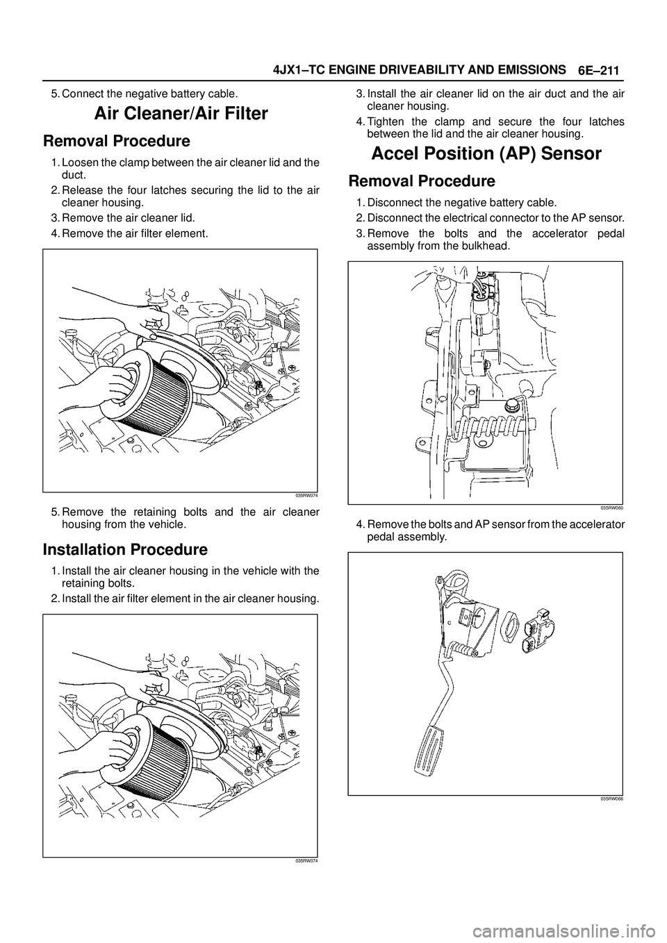
4. Remove the air filter element.
035RW074
5. Remove the retaining bolts and the air cleaner
housing from the vehicle.
Installation Procedure
1. Install the air cleaner housing in the vehicle with the
retaining bolts.
2. Install the air filter element in the air cleaner housing.
035RW074
3. Install the air cleaner lid on the air duct and the air
cleaner housing.
4. Tighten the clamp and secure the four latches
between the lid and the air cleaner housing.
Accel Position (AP) Sensor
Removal Procedure
1. Disconnect the negative battery cable.
2. Disconnect the electrical connector to the AP sensor.
3. Remove the bolts and the accelerator pedal
assembly from the bulkhead.
035RW060
4. Remove the bolts and AP sensor from the accelerator
pedal assembly.
035RW066
Page 2105 of 3573
6E±212
4JX1±TC ENGINE DRIVEABILITY AND EMISSIONS
Installation Procedure
1. Install the AP sensor to the accelerator pedal
assembly.
035RW066
2. Install the accelerator pedal assembly to the
bulkhead.
3. Connect the electrical connector to the AP sensor.
035RW060
4. Connect the negative battery cable.
Accelerator Pedal Replacement
Removal Procedure
1. Disconnect the negative battery cable.
2. Disconnect the electrical connector to the AP sensor.3. Remove the bolts and the accelerator pedal
assembly from the bulkhead.
035RW060
4. Remove the bolts and AP sensor from the accelerator
pedal assembly.
035RW066
Installation Procedure
1. Install the AP sensor to the accelerator pedal
assembly.
2. Install the accelerator pedal assembly to the
bulkhead.
Page 2106 of 3573
6E±213 4JX1±TC ENGINE DRIVEABILITY AND EMISSIONS
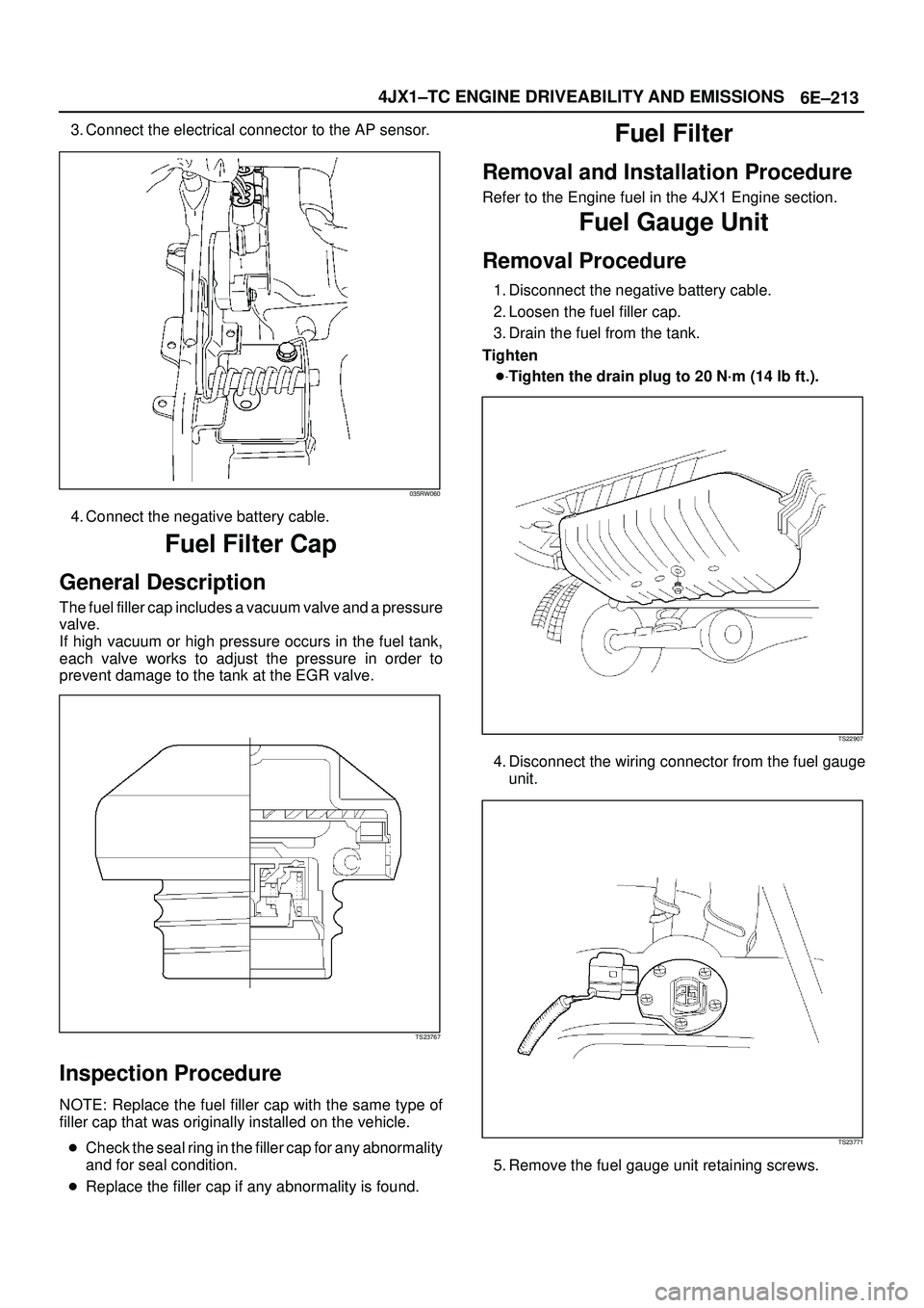
3. Connect the electrical connector to the AP sensor.
035RW060
4. Connect the negative battery cable.
Fuel Filter Cap
General Description
The fuel filler cap includes a vacuum valve and a pressure
valve.
If high vacuum or high pressure occurs in the fuel tank,
each valve works to adjust the pressure in order to
prevent damage to the tank at the EGR valve.
TS23767
Inspection Procedure
NOTE: Replace the fuel filler cap with the same type of
filler cap that was originally installed on the vehicle.
�Check the seal ring in the filler cap for any abnormality
and for seal condition.
�Replace the filler cap if any abnormality is found.
Fuel Filter
Removal and Installation Procedure
Refer to the Engine fuel in the 4JX1 Engine section.
Fuel Gauge Unit
Removal Procedure
1. Disconnect the negative battery cable.
2. Loosen the fuel filler cap.
3. Drain the fuel from the tank.
Tighten
�Tighten the drain plug to 20 N´m (14 lb ft.).
TS22907
4. Disconnect the wiring connector from the fuel gauge
unit.
TS23771
5. Remove the fuel gauge unit retaining screws.
Page 2107 of 3573
6E±214
4JX1±TC ENGINE DRIVEABILITY AND EMISSIONS
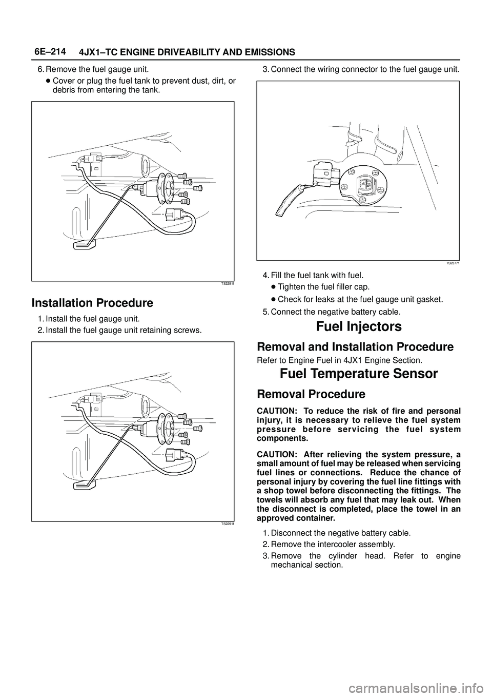
6. Remove the fuel gauge unit.
�Cover or plug the fuel tank to prevent dust, dirt, or
debris from entering the tank.
TS22911
Installation Procedure
1. Install the fuel gauge unit.
2. Install the fuel gauge unit retaining screws.
TS22911
3. Connect the wiring connector to the fuel gauge unit.
TS23771
4. Fill the fuel tank with fuel.
�Tighten the fuel filler cap.
�Check for leaks at the fuel gauge unit gasket.
5. Connect the negative battery cable.
Fuel Injectors
Removal and Installation Procedure
Refer to Engine Fuel in 4JX1 Engine Section.
Fuel Temperature Sensor
Removal Procedure
CAUTION: To reduce the risk of fire and personal
injury, it is necessary to relieve the fuel system
pressure before servicing the fuel system
components.
CAUTION: After relieving the system pressure, a
small amount of fuel may be released when servicing
fuel lines or connections. Reduce the chance of
personal injury by covering the fuel line fittings with
a shop towel before disconnecting the fittings. The
towels will absorb any fuel that may leak out. When
the disconnect is completed, place the towel in an
approved container.
1. Disconnect the negative battery cable.
2. Remove the intercooler assembly.
3. Remove the cylinder head. Refer to engine
mechanical section.
Page 2108 of 3573
6E±215 4JX1±TC ENGINE DRIVEABILITY AND EMISSIONS
4. Remove the rear side engine hanger.
035RW070
5. Remove the fuel return adapter.
035RW069
6. Remove the fuel pressure sensor from the fuel return
adapter.
035RW068
Installation Procedure
1. Install the fuel pressure sensor in the fuel return
adapter.
035RW068