Page 2078 of 3573

6E±185 4JX1±TC ENGINE DRIVEABILITY AND EMISSIONS
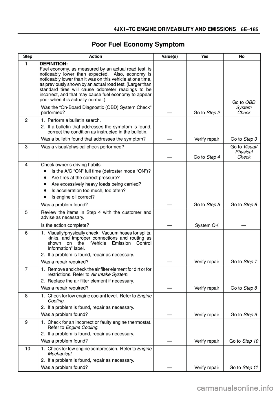
Poor Fuel Economy Symptom�
StepActionValue(s)Ye sNo
1DEFINITION:
Fuel economy, as measured by an actual road test, is
noticeably lower than expected. Also, economy is
noticeably lower than it was on this vehicle at one time,
as previously shown by an actual road test. (Larger than
standard tires will cause odometer readings to be
incorrect, and that may cause fuel economy to appear
poor when it is actually normal.)
Was the ªOn-Board Diagnostic (OBD) System Checkº
performed?
ÐGo to Step 2
Go to OBD
System
Check
21. Perform a bulletin search.
2. If a bulletin that addresses the symptom is found,
correct the condition as instructed in the bulletin.
Was a bulletin found that addresses the symptom?
ÐVerify repairGo to Step 3
3Was a visual/physical check performed?
ÐGo to Step 4
Go to Visual/
Physical
Check
4Check owner's driving habits.
�Is the A/C ªONº full time (defroster mode ªONº)?
�Are tires at the correct pressure?
�Are excessively heavy loads being carried?
�Is acceleration too much, too often?
�Is engine oil correct?
Was a problem found?
ÐGo to Step 5Go to Step 6
5Review the items in Step 4 with the customer and
advise as necessary.
Is the action complete?
ÐSystem OKÐ
61. Visually/physically check: Vacuum hoses for splits,
kinks, and improper connections and routing as
shown on the ªVehicle Emission Control
Informationº label.
2. If a problem is found, repair as necessary.
Was a repair required?
ÐVerify repairGo to Step 7
71. Remove and check the air filter element for dirt or for
restrictions. Refer to
Air Intake System.
2. Replace the air filter element if necessary.
Was a repair required?
ÐVerify repairGo to Step 8
81. Check for low engine coolant level. Refer to Engine
Cooling
.
2. If a problem is found, repair as necessary.
Was a problem found?
ÐVerify repairGo to Step 9
91. Check for an incorrect or faulty engine thermostat.
Refer to
Engine Cooling.
2. If a problem is found, repair as necessary.
Was a problem found?
ÐVerify repairGo to Step 10
101. Check for low engine compression. Refer to Engine
Mechanical
.
2. If a problem is found, repair as necessary.
Was a problem found?
ÐVerify repairGo to Step 11
Page 2089 of 3573

6E±196
4JX1±TC ENGINE DRIVEABILITY AND EMISSIONS
QOS System Doesn't Work�
StepActionValue(s)Ye sNo
1Was OBD System check performed?
ÐGo to Step 2
Go to OBD
System
Check
2Check glawplug indicator light. If bulb is broken,
replace.
Was a problem found?
ÐVerify repairGo to Step 3
31. Connect a circuit tester between glawplug & engine
ground.
2. With ignition on and engine off, check if the glaw
indicator and circuit tester indicate power voltage
for 9 to 13 sec. If not indicated, repair terminal & wire
harness.
Was repair needed?
ÐVerify repairGo to Step 4
41. Connect a circuit tester between glawplug and
engine ground.
2. With engine on, check if voltage continues for 180
sec. If not, inspect and repair glaw relay.
Was repair needed?
ÐVerify repairGo to Step 5
51. Remove the glawplug, and if damaged, replace.
2. Check glawplug resistance.
Was resistance as specified?
0.8 ± 1�Go to Step 7Go to Step 6
6Replace glawplug.
Was measure completed?
ÐVerify repairGo to Step 7
71. Review all diagnostic procedures within this table.
2. If all procedures have been completed and no
malfunctions have been found, review/inspect the
following:
�Visual/physical inspection
�Tech 2 data
�Freeze Frame data/Failure Records butter
�All electrical connections within a suspected
circuit and/or system
3. If a problem is found, repair as necessary.
Was a problem found?
ÐVerify repair
Contact
Technical
Assistance
Page 2094 of 3573
6E±201 4JX1±TC ENGINE DRIVEABILITY AND EMISSIONS
On±Vehicle Service
Camshaft Position (CMP)
Sensor
Removal Procedure
1. Disconnect the negative battery cable.
2. Disconnect the electrical connector to the CMP
sensor.
035RW071
3. Remove the CMP sensor retaining bolt from the
cylinder head cover.
035RW075
Inspection Procedure
1. Inspect the sensor O-ring for cracks or leaks.
2. Replace the O-ring if it is worn or damaged.
3. Lubricate the new O-ring with engine oil.
4. Install the lubricated O-ring.
Installation Procedure
1. Install the CMP sensor in the cylinder head cover.
2. Install the CMP sensor retaining bolt.
Tighten
�Tighten the retaining bolt to 9 N´m (78 lb in.).
035RW075
3. Connect the electrical connector to the CMP sensor.
035RW071
4. Connect the negative battery cable.
Page 2095 of 3573
6E±202
4JX1±TC ENGINE DRIVEABILITY AND EMISSIONS
Crankshaft Position (CKP)
Sensor
Removal Procedure
1. Disconnect the negative battery cable.
2. Remove the under cover.
035RW091
3. Disconnect the electrical connector to the CKP
sensor.
4. Remove one bolt and the CKP sensor from the left
side of the engine block.
NOTE: Use caution to avoid any hot oil that might drip
out.
035RW090
Inspection Procedure
1. Inspect the sensor O-ring for cracks or leaks.
2. Replace the O-ring if it is worn or damaged.
3. Lubricate the new O-ring with engine oil.
4. Install the lubricated O-ring.
Installation Procedure
1. Install the CKP sensor in the engine block.
2. Install the CKP sensor mounting bolt.
Tighten
�Tighten the mounting bolt to 9 N´m (78 lb in.).
035RW090
3. Connect the electrical connector to the CKP sensor.
4. Install the under cover.
035RW091
5. Connect the negative battery cable.
Page 2096 of 3573

6E±203 4JX1±TC ENGINE DRIVEABILITY AND EMISSIONS
Engine Coolant Temperature
(ECT) Sensor
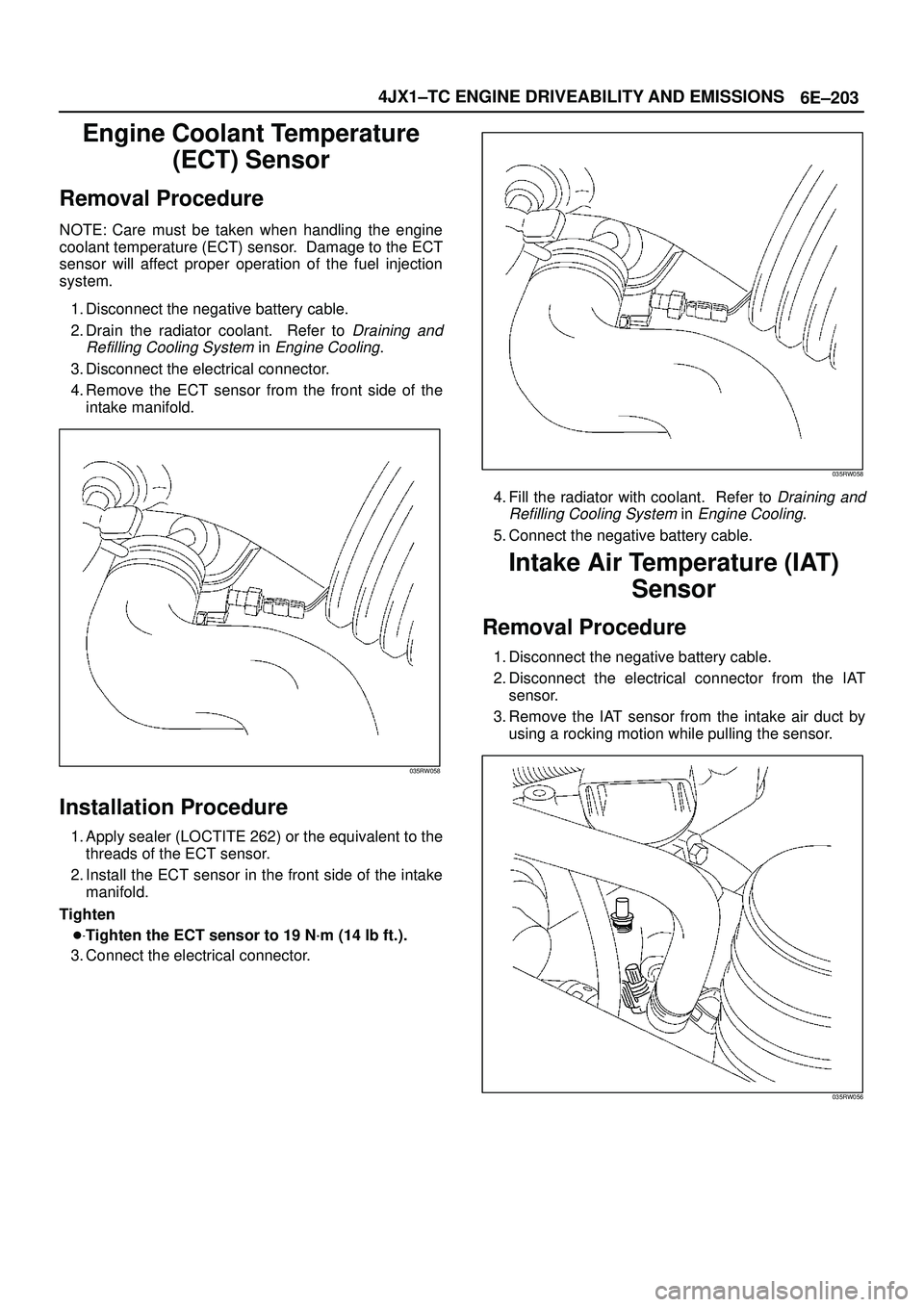
Removal Procedure
NOTE: Care must be taken when handling the engine
coolant temperature (ECT) sensor. Damage to the ECT
sensor will affect proper operation of the fuel injection
system.
1. Disconnect the negative battery cable.
2. Drain the radiator coolant. Refer to
Draining and
Refilling Cooling System
in Engine Cooling.
3. Disconnect the electrical connector.
4. Remove the ECT sensor from the front side of the
intake manifold.
035RW058
Installation Procedure
1. Apply sealer (LOCTITE 262) or the equivalent to the
threads of the ECT sensor.
2. Install the ECT sensor in the front side of the intake
manifold.
Tighten
�Tighten the ECT sensor to 19 N´m (14 lb ft.).
3. Connect the electrical connector.
035RW058
4. Fill the radiator with coolant. Refer to Draining and
Refilling Cooling System
in Engine Cooling.
5. Connect the negative battery cable.
Intake Air Temperature (IAT)
Sensor
Removal Procedure
1. Disconnect the negative battery cable.
2. Disconnect the electrical connector from the IAT
sensor.
3. Remove the IAT sensor from the intake air duct by
using a rocking motion while pulling the sensor.
035RW056
Page 2097 of 3573
6E±204
4JX1±TC ENGINE DRIVEABILITY AND EMISSIONS
Installation Procedure
1. Install the IAT sensor into the grommet in the intake
air duct.
035RW056
2. Correct the IAT electrical connector.
3. Connect the negative battery cable.
Manifold Absolute Pressure
(MAP) Sensor
Removal Procedure
1. Disconnect the negative battery cable.
2. Disconnect the EGR valve.
035RW054
3. Disconnect the MAP sensor connector from the MAP
sensor.
035RW053
4. Remove the bolts and the MAP sensor from the
intake manifold.
035RW057
Page 2098 of 3573
6E±205 4JX1±TC ENGINE DRIVEABILITY AND EMISSIONS
Installation Procedure
1. Install the MAP sensor and bolts on the intake
manifold.
Torque: 4 N´m (35 lb in)
035RW057
2. Connect the MAP sensor connector.
035RW053
3. Connect the EGR valve.
035RW054
4. Connect the negative battery cable.
Oil Temperature (OT) Sensor
Removal Procedure
1. Disconnect the negative battery cable.
2. Remove the battery.
035RW095
Page 2099 of 3573

6E±206
4JX1±TC ENGINE DRIVEABILITY AND EMISSIONS
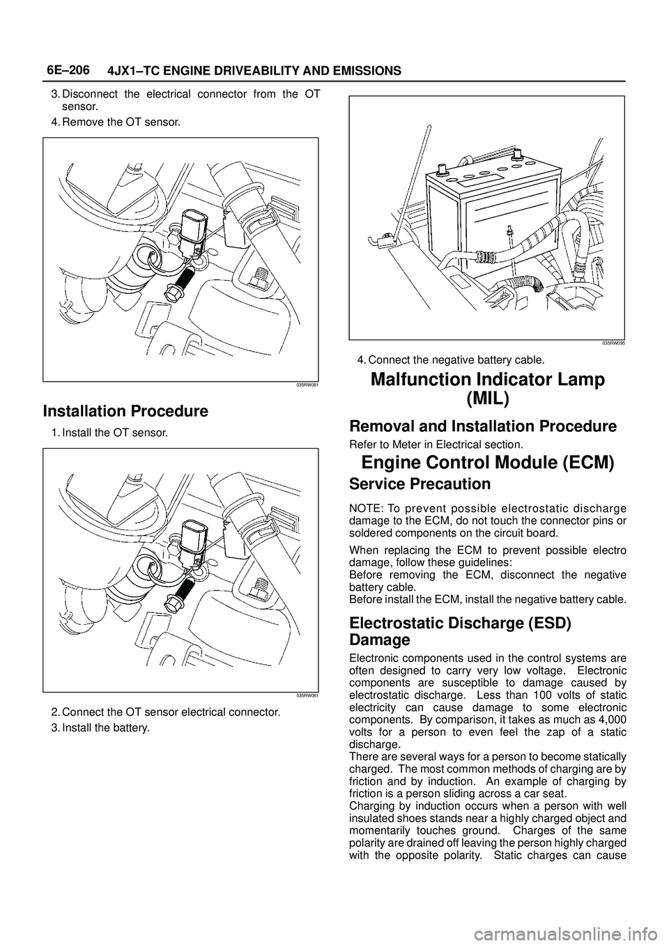
3. Disconnect the electrical connector from the OT
sensor.
4. Remove the OT sensor.
035RW061
Installation Procedure
1. Install the OT sensor.
035RW061
2. Connect the OT sensor electrical connector.
3. Install the battery.
035RW095
4. Connect the negative battery cable.
Malfunction Indicator Lamp
(MIL)
Removal and Installation Procedure
Refer to Meter in Electrical section.
Engine Control Module (ECM)
Service Precaution
NOTE: To p r e ve n t p ossible electrostatic discharge
damage to the ECM, do not touch the connector pins or
soldered components on the circuit board.
When replacing the ECM to prevent possible electro
damage, follow these guidelines:
Before removing the ECM, disconnect the negative
battery cable.
Before install the ECM, install the negative battery cable.
Electrostatic Discharge (ESD)
Damage
Electronic components used in the control systems are
often designed to carry very low voltage. Electronic
components are susceptible to damage caused by
electrostatic discharge. Less than 100 volts of static
electricity can cause damage to some electronic
components. By comparison, it takes as much as 4,000
volts for a person to even feel the zap of a static
discharge.
There are several ways for a person to become statically
charged. The most common methods of charging are by
friction and by induction. An example of charging by
friction is a person sliding across a car seat.
Charging by induction occurs when a person with well
insulated shoes stands near a highly charged object and
momentarily touches ground. Charges of the same
polarity are drained off leaving the person highly charged
with the opposite polarity. Static charges can cause