Page 1850 of 3573
ENGINE FUEL 6C – 5
FUEL FILTER
Legend
(1) Priming Pump
(2) Fuel Filter Cartridge
A cartridge type fuel filter is used along with the piston
type fuel pump on the high pressure oil pump.
The fuel filter removes foreign material from the fuel
before it reaches the fuel pump.
A diaphragm type priming pump is installed at the top of
the fuel filter. It is used during the air bleeding
procedures.
INJECTOR ASSEMBLY
Legend
(1) Oil Passage
(2) Fuel Passage
1. Construction of Fuel Injector
The fuel injector is comprised of the solenoid
section, hydraulic line, and fuel line. Fuel injection is
controlled by the continuity time signal and
continuity start timing signal sent by the ECM
(Electronic Control Module) to the solenoid.
2. Working of Fuel Injector
1) The ECM detects the working of the engine from
its input signals, such as engine speed
accelerator throttle opening, and engine coolant
temperature, sending the optimal signals to the
solenoid.
1
2
041RW017
1
2
055RW018
Page 1852 of 3573
ENGINE FUEL 6C – 7
ON-VEHICLE SERVICE
FUEL FILTER ASSEMBLY
REMOVAL
1. Disconnect battery ground cable.
2. Fuel Filler cap
3. Fuel Hose
1) Disconnect fuel hose from filter body.
Plug the hose ends to prevent fuel spillage.
4. Remove the Bolt on Fuel Filter Bracket
5. Remove Fuel Filter Assembly
INSTALLATION
1. Install the fuel filter assembly
2. Tighten the Fuel Filter Bracket Fixing Bolt
3. Fuel Hose
1) Connect hoses to filter body.
4. Fuel Filler Cap
1) Connect the battery ground cable.
2) Feed fuel to the fuel pump by priming, and bleed
the air from fuel system.
FUEL FILTER CARTRIDGE
DISASSEMBLY
1. Drain fuel completely from the fuel filter.
2. Protect the filter body with cloth and lightly grip with
a vise.
3. Remove the cartridge using a filter wrench.
Filter wrench: 5-8840-0203-0
1
Legend
(1) Priming Pump
012RW111
012RW112
Page 1855 of 3573

6C – 10 ENGINE FUEL
REMOVAL
Prior to removal, be sure to confirm and record the
group code of the injector installed using Tech2.
1. Disconnect battery ground cable.
2. Remove air cleaner cover and air duct.
3. Remove intercooler.
Refer to “Intercooler” in this manual.
4. Remove PCV hose and pipe.
5. Remove cylinder head noise insulator cover.
6. Remove high pressure oil pipe.
CAUTION:
1) Sleeve nut should be loosened with cloth tied
around to prevent oil from spurting due to the
remaining pressure.
2) High oil pressure pipe should be disconnected
with cloth tied around the intake manifold glow
plug to prevent oil from flowing out of the oil
rail.
7. Loosen eye bolt of fuel pipe at fuel pump side.
NOTE: Cloth should be put around the loosened eye
bolt to prevent fuel from flowing out.
8. Remove fuel return hose at chassis side.
9. Remove PCV hose to cylinder head cover.
10. Remove cylinder head cover.
11. Drain the oil from oil rail assembly.
NOTE: Do not drop O-ring
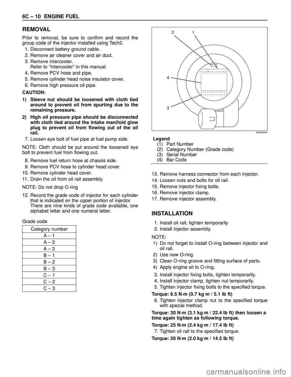
12. Record the grade code of injector for each cylinder
that is indicated on the upper portion of injector.
There are nine kinds of grade code available, one
alphabet letter and one numeral letter.
Grade codeLegend
(1) Part Number
(2) Category Number (Grade code)
(3) Serial Number
(4) Bar Code
13. Remove harness connector from each injector.
14. Loosen nuts and bolts for oil rail.
15. Remove injector fixing bolts.
16. Remove injector clamp.
17. Remove injector assembly.
INSTALLATION
1. Install oil rail, tighten temporarily
2. Install injector assembly.
NOTE:
1) Do not forget to install O-ring between injector and
oil rail.
2) Use new O-ring
3) Clean O-ring groove and fitting surface of parts.
4) Apply engine oil to O-ring.
3. Install injector fixing bolts, tighten temporarily.
4. Install injector clamp, tighten nut temporarily.
5. Tighten injector fixing bolts to the specified torque.
Torque: 6.5 N·m (0.7 kg·m / 5.1 lb ft)
6. Tighten injector clamp nut to the specified torque
with special method.
Torque: 30 N·m (3.1 kg·m / 22.4 lb ft) then loosen a
time again tighten as following torque.
Torque: 25 N·m (2.4 kg·m / 17.4 lb ft)
7. Tighten oil rail to the specified torque.
Torque: 20 N·m (2.0 kg·m / 14.5 lb ft)
1
4
32
055RW00001
Category number
A– 1
A– 2
A– 3
B – 1
B – 2
B – 3
C – 1
C – 2
C – 3
Page 1858 of 3573
ENGINE FUEL 6C – 13
FUEL PUMP PIPE
6
23
10
98 5
4
7
1
Legend
(1) Cap Nut
(2) Gasket
(3) Gasket
(4) Pipe Nut
(5) Adapter(6) Gasket
(7) Fuel Pump Pipe
(8) Eye Bolt
(9) Gasket
(10) Gasket
040R200002
REMOVAL
1. Remove eye bolt.
2. Remove cap nut.
NOTE: The eye bolt and cap nut should be
disconnected with cloth tied around them to prevent
flowing out of fuel.
3. Remove fuel pump pipe.
4. Remove pipe nut.
5. Remove adapter.
INSTALLATION
1. Apply engine oil to the thread, then install adapter
with new gasket.
Torque : 16 N·m (1.6 kg·m/12 lb ft)
NOTE: Be careful not to enter the foreign material.
2. Apply engine oil to the thread, then install pipe nut.
Torque : 10 N·m (1.0 kg·m/87 lb ft)
NOTE: Do not apply oil to cap nut side.
3. Install fuel pump pipe, new gaskets and cap nut to
adapter temporarily. Do not tighten the cap nut.
4. Install eye bolt with new gasket then tighten to
specified torque.
Torque : 29 N·m (3.0 kg·m/22 lb ft)
Page 1860 of 3573
ENGINE FUEL 6C – 15
HIGH PRESSURE OIL PUMP
REMOVAL
1. Disconnect battery ground cable.
2. Remove air cleaner cover and air duct
3. Intercooler assembly
Refer to “Intercooler” in this manual.
4. Remove high pressure oil pipe
5. Timing belt cover
Disconnect CMP sensor cable.
Remove CMP sensor bracket.
6. Tensioner
7. Timing Belt
8. Remove high pressure oil pump timing pulley
9. Remove crankshaft damper pulley
10. Remove timing gear case cover
11. Remove idle gear A
Before removing idle gear A, set two bolts to the
sub gear of idle gear A and turn it to align the teeth
of idle gear A main gear.
Then lock them by bolts as shown in the illustration.Legend
(1) Idle gear A sub gear
(2) Idle gear A main gear
(3) Bar
(4) Lock bolt
1
2
43
Legend
(1) O-Ring
(2) High Pressure Oil Pump Assembly
(3) Nut
(4) O-Ring
040RW007
4 1
2
3
014RW177
Page 1861 of 3573
6C – 16 ENGINE FUEL
12. Remove high pressure oil pump
13. Remove high pressure oil pump assembly
Legend
(1) O-ring
(2) High pressure oil pump
(3) Nut
(4) O-ring
1
2
43
040RW007
Page 1863 of 3573

6C – 18 ENGINE FUEL
4. Remove lock bolt of idle gear A.
5. Install timing gear case cover.
Refer to “Timing gear” in this manual.
6. Install front plate.
Torque: 20 N·m (2.0 kg·m/14.5 lb ft)
7. Install timing pulley of high pressure oil pump.
Torque: 10 N·m (1.0 kg·m/7.2 lb ft)
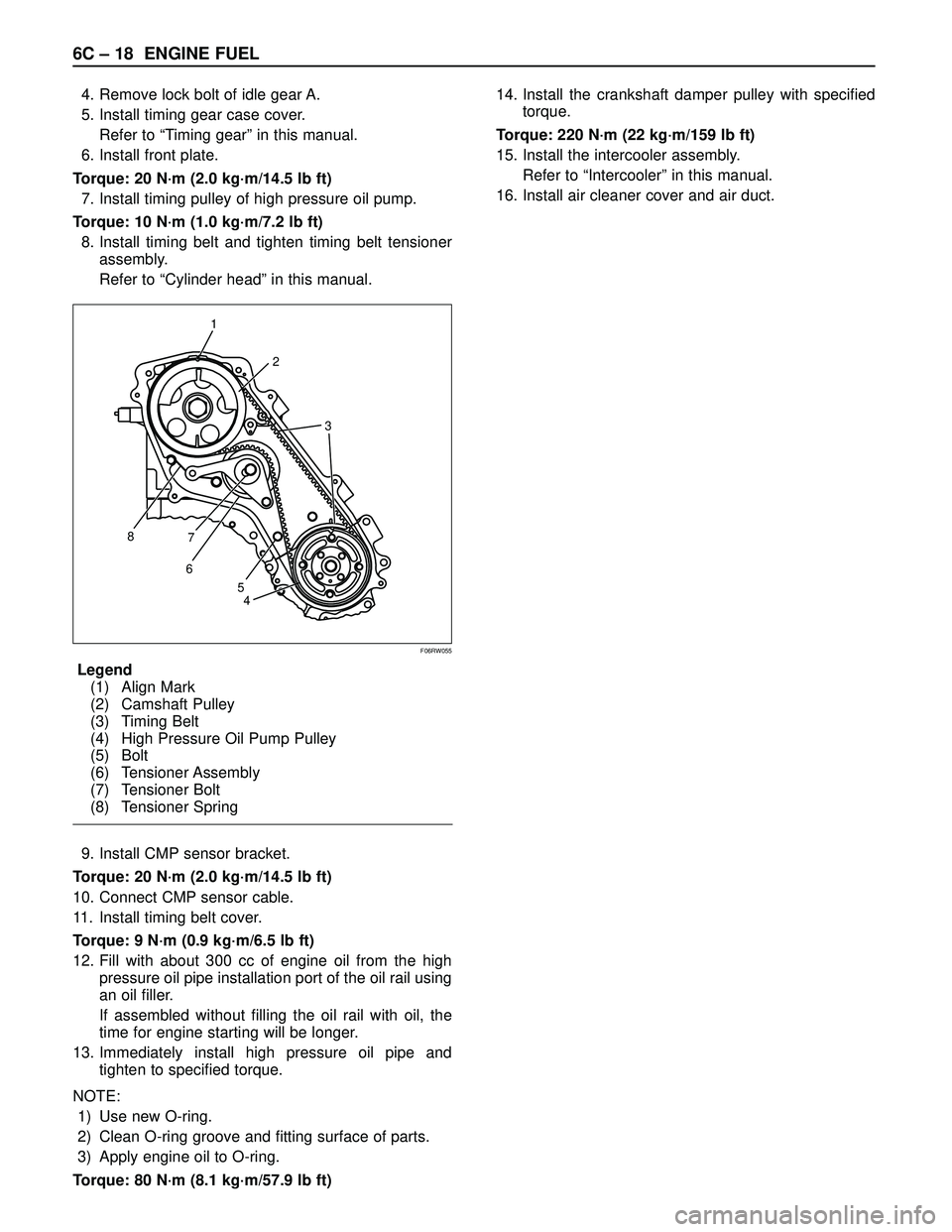
8. Install timing belt and tighten timing belt tensioner
assembly.
Refer to “Cylinder head” in this manual.
Legend
(1) Align Mark
(2) Camshaft Pulley
(3) Timing Belt
(4) High Pressure Oil Pump Pulley
(5) Bolt
(6) Tensioner Assembly
(7) Tensioner Bolt
(8) Tensioner Spring
9. Install CMP sensor bracket.
Torque: 20 N·m (2.0 kg·m/14.5 lb ft)
10. Connect CMP sensor cable.
11. Install timing belt cover.
Torque: 9 N·m (0.9 kg·m/6.5 lb ft)
12. Fill with about 300 cc of engine oil from the high
pressure oil pipe installation port of the oil rail using
an oil filler.
If assembled without filling the oil rail with oil, the
time for engine starting will be longer.
13. Immediately install high pressure oil pipe and
tighten to specified torque.
NOTE:
1) Use new O-ring.
2) Clean O-ring groove and fitting surface of parts.
3) Apply engine oil to O-ring.
Torque: 80 N·m (8.1 kg·m/57.9 lb ft)14. Install the crankshaft damper pulley with specified
torque.
Torque: 220 N·m (22 kg·m/159 lb ft)
15. Install the intercooler assembly.
Refer to “Intercooler” in this manual.
16. Install air cleaner cover and air duct.
1
2
3
8
67
4 5
F06RW055
Page 1864 of 3573

ENGINE FUEL 6C – 19
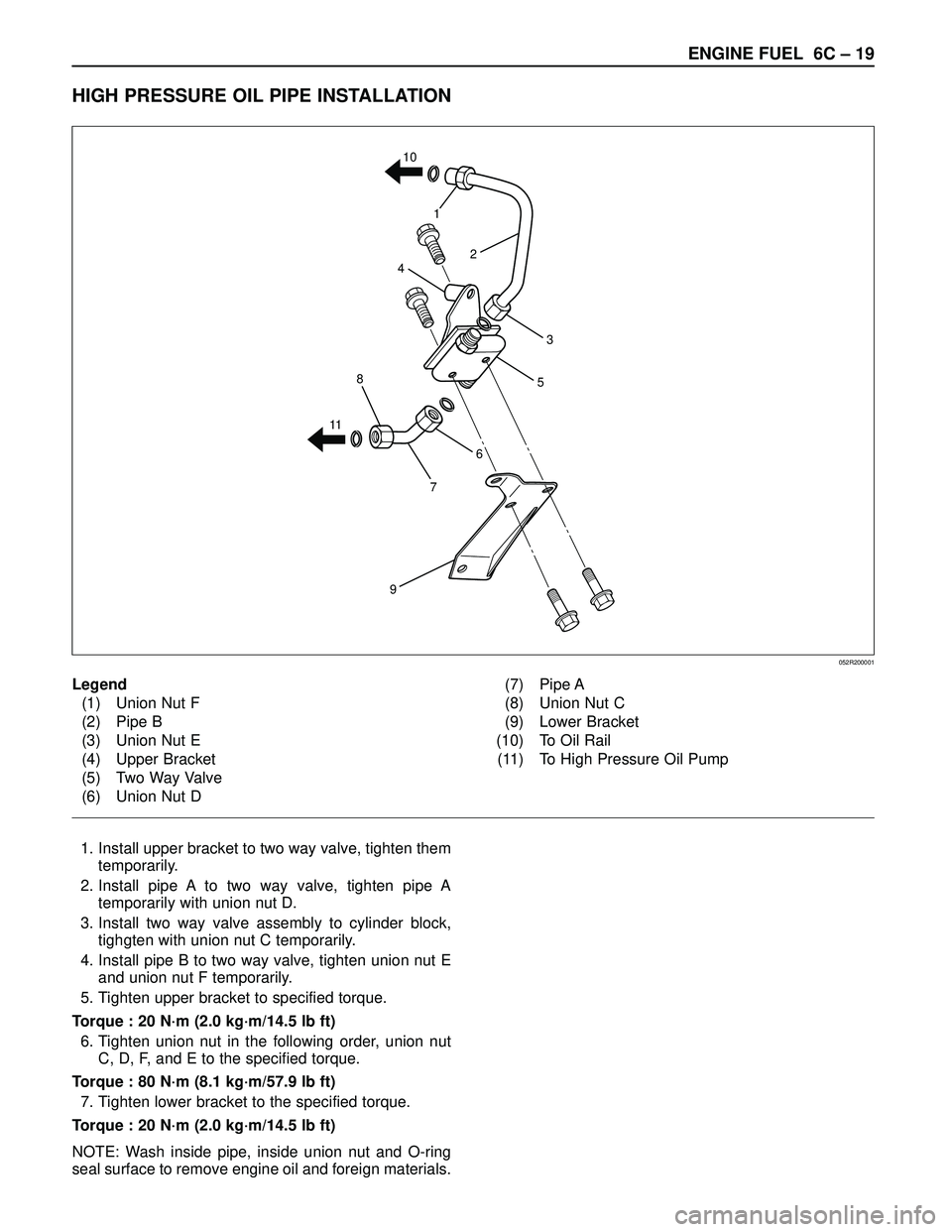
HIGH PRESSURE OIL PIPE INSTALLATION
1. Install upper bracket to two way valve, tighten them
temporarily.
2. Install pipe A to two way valve, tighten pipe A
temporarily with union nut D.
3. Install two way valve assembly to cylinder block,
tighgten with union nut C temporarily.
4. Install pipe B to two way valve, tighten union nut E
and union nut F temporarily.
5. Tighten upper bracket to specified torque.
Torque : 20 N·m (2.0 kg·m/14.5 lb ft)
6. Tighten union nut in the following order, union nut
C, D, F, and E to the specified torque.
Torque : 80 N·m (8.1 kg·m/57.9 lb ft)
7. Tighten lower bracket to the specified torque.
Torque : 20 N·m (2.0 kg·m/14.5 lb ft)
NOTE: Wash inside pipe, inside union nut and O-ring
seal surface to remove engine oil and foreign materials.
6
5
7
9
8
114
1
2
3 10
Legend
(1) Union Nut F
(2) Pipe B
(3) Union Nut E
(4) Upper Bracket
(5) Two Way Valve
(6) Union Nut D(7) Pipe A
(8) Union Nut C
(9) Lower Bracket
(10) To Oil Rail
(11) To High Pressure Oil Pump
052R200001