Page 155 of 3573
AIR CONDITIONING 1B Ð 29
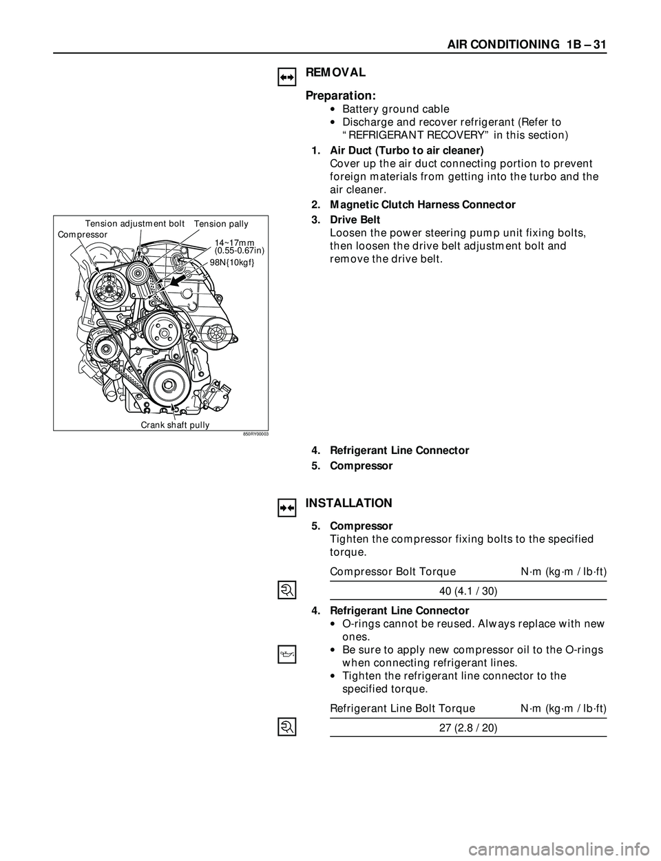
3. Drive Belt
1) Temporary tighten the power steering pump unit
fixing bolts.
2) Push the drive belt when the force of 98N {10kgf}.,
and adjust the drive belt tension by tightening
drive belt tension adjustment bolt, till the 14 ~17
mm (0.55 ~0.67 in) of deflection of the belt is
obtained. Then tighten the power steering pump
fixing bolts.
2. Magnetic Clutch Harness Connector
1. Air Duct (Turbo to air cleaner)
Power steering
pump pulley
Tension adjustment
bolt
Crank pulley Drive beltCompressor98N{10kgf}
14�™17mm
(0.55�™
0.67 in.)
850RY00002
Page 156 of 3573
1B Ð 30 AIR CONDITIONING
Removal Steps
1. Air duct
2. Compressor bracket
3. Magnetic clutch harness
connector
4. Compressor
5. Drive belt
6. Refrigerant line connector
Installation Steps
To install, follow the removal steps in the
reverse order.
4JX1 ENGINE
1
5 46
3
2
852RY00011
Page 157 of 3573

AIR CONDITIONING 1B Ð 31
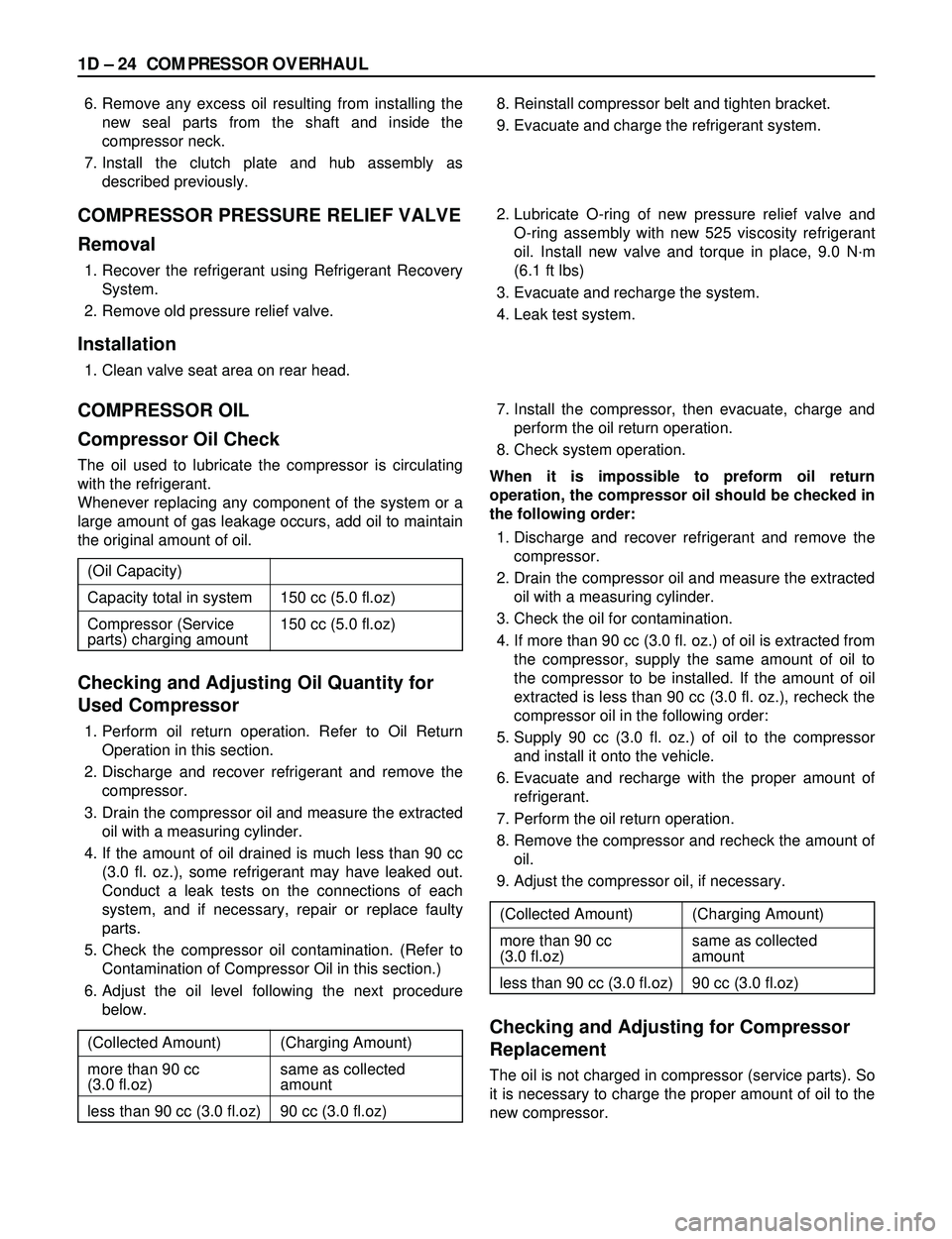
REMOVAL
Preparation:
·Battery ground cable
·Discharge and recover refrigerant (Refer to
ÒREFRIGERANT RECOVERYÓ in this section)
1. Air Duct (Turbo to air cleaner)
Cover up the air duct connecting portion to prevent
foreign materials from getting into the turbo and the
air cleaner.
2. Magnetic Clutch Harness Connector
3. Drive Belt
Loosen the power steering pump unit fixing bolts,
then loosen the drive belt adjustment bolt and
remove the drive belt.
4. Refrigerant Line Connector
5. Compressor
CompressorTension adjustment bolt
Tension pally
14~17mm
(0.55-0.67in)
98N{10kgf}
Crank shaft pully
INSTALLATION
5. Compressor
Tighten the compressor fixing bolts to the specified
torque.
Compressor Bolt Torque Nám (kgám / lbáft)
40 (4.1 / 30)
4. Refrigerant Line Connector
·O-rings cannot be reused. Always replace with new
ones.
·Be sure to apply new compressor oil to the O-rings
when connecting refrigerant lines.
·Tighten the refrigerant line connector to the
specified torque.
Refrigerant Line Bolt Torque Nám (kgám / lbáft)
27 (2.8 / 20)
850RY00003
Page 158 of 3573
1B Ð 32 AIR CONDITIONING
3. Drive Belt
1) Temporary tighten the power steering pump unit
fixing bolts.
2) Push the drive belt when the force of 98N {10kgf}.,
and adjust the drive belt tension by tightening
drive belt tension adjustment bolt, till the 14 ~17
mm (0.55 ~0.67 in) of deflection of the belt is
obtained. Then tighten the power steering pump
fixing bolts.
2. Magnetic Clutch Harness Connector
1. Air Duct (Turbo to air cleaner)
CompressorTension adjustment bolt
Tension pally
14~17mm
(0.55-0.67in)
98N{10kgf}
Crank shaft pully
850RY00003
Page 202 of 3573
1BÐ76 AIR CONDITIONING
10
71
1
5
6
12
13
11
2
3
4
8
9
852RY00001
Legend
(1) Liquid Line (High Pressure Pipe)
(2) Pressure Switch
(3) Ambient Sensor
(4) Receiver Drier
(5) Discharge Line (High Pressure Hose)
(6) Suction Line (Low Pressure Hose)(7) Compressor
(8) Condenser Assembly
(9) Drive Belt
(10) Compressor Bracket
(11) Drain Hose
(12) Evaporator Assembly
(13) O-ring
AIR CONDITIONING PARTS
6VE1 (RHD)
Page 203 of 3573
AIR CONDITIONING 1BÐ77
910
6
12
13
3
2
4
5
7
8 11
1
852RY00002
Legend
(1) Liquid Line (High-Pressure Pipe)
(2) O-ring
(3) Discharge Line (High-Pressure Hose)
(4) Pressure Switch
(5) Receiver Drier
(6) Ambient Sensor(7) Condenser Assembly
(8) Drive Belt
(9) Compressor
(10) Drain Hose
(11) Suction Line (Low-Pressure Hose)
(12) Evaporator Assembly
(13) A/C Switch
6VE1 (LHD)
Page 280 of 3573

1D Ð 24 COMPRESSOR OVERHAUL
6. Remove any excess oil resulting from installing the
new seal parts from the shaft and inside the
compressor neck.
7. Install the clutch plate and hub assembly as
described previously.8. Reinstall compressor belt and tighten bracket.
9. Evacuate and charge the refrigerant system.
COMPRESSOR PRESSURE RELIEF VALVE
Removal
1. Recover the refrigerant using Refrigerant Recovery
System.
2. Remove old pressure relief valve.
Installation
1. Clean valve seat area on rear head.2. Lubricate O-ring of new pressure relief valve and
O-ring assembly with new 525 viscosity refrigerant
oil. Install new valve and torque in place, 9.0 Nám
(6.1 ft lbs)
3. Evacuate and recharge the system.
4. Leak test system.
COMPRESSOR OIL
Compressor Oil Check
The oil used to lubricate the compressor is circulating
with the refrigerant.
Whenever replacing any component of the system or a
large amount of gas leakage occurs, add oil to maintain
the original amount of oil.
Checking and Adjusting Oil Quantity for
Used Compressor
1. Perform oil return operation. Refer to Oil Return
Operation in this section.
2. Discharge and recover refrigerant and remove the
compressor.
3. Drain the compressor oil and measure the extracted
oil with a measuring cylinder.
4. If the amount of oil drained is much less than 90 cc
(3.0 fl. oz.), some refrigerant may have leaked out.
Conduct a leak tests on the connections of each
system, and if necessary, repair or replace faulty
parts.
5. Check the compressor oil contamination. (Refer to
Contamination of Compressor Oil in this section.)
6. Adjust the oil level following the next procedure
below.7. Install the compressor, then evacuate, charge and
perform the oil return operation.
8. Check system operation.
When it is impossible to preform oil return
operation, the compressor oil should be checked in
the following order:
1. Discharge and recover refrigerant and remove the
compressor.
2. Drain the compressor oil and measure the extracted
oil with a measuring cylinder.
3. Check the oil for contamination.
4. If more than 90 cc (3.0 fl. oz.) of oil is extracted from
the compressor, supply the same amount of oil to
the compressor to be installed. If the amount of oil
extracted is less than 90 cc (3.0 fl. oz.), recheck the
compressor oil in the following order:
5. Supply 90 cc (3.0 fl. oz.) of oil to the compressor
and install it onto the vehicle.
6. Evacuate and recharge with the proper amount of
refrigerant.
7. Perform the oil return operation.
8. Remove the compressor and recheck the amount of
oil.
9. Adjust the compressor oil, if necessary.
Checking and Adjusting for Compressor
Replacement
The oil is not charged in compressor (service parts). So
it is necessary to charge the proper amount of oil to the
new compressor. (Oil Capacity)
Capacity total in system 150 cc (5.0 fl.oz)
Compressor (Service 150 cc (5.0 fl.oz)
parts) charging amount
(Collected Amount) (Charging Amount)
more than 90 cc same as collected
(3.0 fl.oz) amount
less than 90 cc (3.0 fl.oz) 90 cc (3.0 fl.oz)
(Collected Amount) (Charging Amount)
more than 90 cc same as collected
(3.0 fl.oz) amount
less than 90 cc (3.0 fl.oz) 90 cc (3.0 fl.oz)
Page 312 of 3573

2A – 10 POWER STEERING
POWER STEERING SYSTEM TEST
TEST PROCEDURE
Test of fluid pressure in the power steering system
is performed to determine whether or not the oil
pump and power steering unit are functioning
normally.
The power steering system test is method used to
identify and isolate hydraulic circuit difficulties.
Prior to performing this test, the following
inspections and corrections, if necessary, must be
made.
INSPECT
•Pump reservoir for proper fluid level.
•Pump belt for proper tension.
•Pump driver pulley condition.
1. Place a container under the pump to catch the
fluid when disconnecting or connecting the
hoses.
2. With the engine NOT running , disconnect the
pressure hose at the power steering pump and
install Power Steering tester.
The gage must be between the shutoff valve
and pump. Open the shutoff valve.
Tester: 5-8840-0135-0 (J-29877-A)
Adapter: 5-8840-2297-0 (For 6VD1, 6VE1, 4JX1)
5-8840-0136-0 (For 4JG2)3. Check the fluid level. Fill the reservoir with
power steering fluid, to the “Full” mark. Start
the engine then turn the steering wheel and
momentarily hold it against a stop. Turn off
and check the connections at tester for leakage.
4. Bleed the system. Refer to “Bleeding the
Power Steering System” in this section.
5. Start the engine and check the pump fluid
level. Add power steering fluid if required.
When the engine is at normal operating
temperature, increase engine speed to 1500
rpm.
CAUTION:
Do not leave shutoff valve fully closed for more
than 5 seconds, as the pump could become
damaged internally.
6. Fully close the shutoff valve. Record the
highest pressures.
•If the pressure recorded is within 9300-9800
kPa (1350-1420 psi) For 6VD1, 6VE1, and
9800-10300 kPa (100-105 kg/cm
2/ 1420-1490
psi) For 4JG2, 4JX1, the pump is functioning
within its specifications.
•If the pressure recorded is higher than 9800
kPa (1420 psi) For 6VD1, 6VE1, and 10300
kPa (105 kg/cm
2/ 1490 psi) For 4JG2, 4JX1,
the valve in the pump is defective.