Page 314 of 3573

BLEEDING THE POWER
STEERING SYSTEM
When a power steering pump or gear has been
installed, or an oil line has been disconnected, the
air that has entered the system must be bled out
before the vehicle is operated. If air is allowed to
remain in the power steering fluid system, noisy
and unsatisfactory operation of the system may
result.
BLEEDING PROCEDURE
When bleeding the system, and any time fluid is
added to the power steering system, be sure to use
only power steering fluid as specified in
“MAINTENANCE AND LUBRICATION” in section
0B.
1. Fill the pump fluid reservoir to the proper
level and let the fluid settle for at least two
minutes.
2. Start the engine and let it run for a few
seconds.
Do not turn the steering wheel. Then turn the
engine off.
3. Add fluid if necessary.
4. Repeat the above procedure until the fluid
level remains constant after running the
engine.
5. Raise the front end of the vehicle so that the
wheels are off the ground.
6. Start the engine. Slowly turn the steering
wheel right and left, lightly contacting the
wheel stops.
7. Add power steering fluid if necessary.
8. Bring down the vehicle, set the steering wheel
at the straight forward position after turning it
to its full steer positions 2 or 3 times, and stop
the engine.
9. Stop the engine. Check the fluid level and
refill as required.
10. If the fluid is extremely foamy, allow the
vehicle to stand a few minutes and repeat the
above procedure.
INSPECT
•Belt for tightness.
•Pulley for looseness or damage. The pulley
should not wobble with the engine running.
•Make sure that hose and pipes are properly
fitted.
•Fluid level and fill to the proper level.
FLUSHING THE POWER
STEERING SYSTEM
1. Raise the front end of the vehicle off the
ground until the wheels are free to turn.
2. Remove the fluid return line at the reservoir
inlet connector and plug the connector.
Position the line toward a large container to
catch the draining fluid.
3. While running the engine at idle, fill the
reservoir with new power steering fluid. Turn
the steering wheel in both directions. Do not
contact wheel stops or hold the wheel in a
corner, or fluid will stop and the pump will be
in pressure relief mode. A sudden overflow
from the reservoir may develop if the wheel is
held at a stop.
4. While refilling the reservoir, check the
draining fluid for contamination. If foreign
material is still evident, replace all lines,
disassemble and clean or replace the power
steering system components. Do not re-use
any drained power steering fluid.
5. Install all the lines and hoses. Fill the system
with new power steering fluid and bleed the
system as described in “Bleeding The Power
Steering System”. Operate the engine for
about 15 minutes. 2A – 12 POWER STEERING
ON-VEHICLE SERVICE
Page 315 of 3573
POWER STEERING 2A – 13
STEERING GEAR
Removal Steps
1. Pipe
2. Nut
3. Pitman arm
4. Universal joint bolt
5. Gear box mounting bolt and nut
6. Gear box
Installation Steps
6. Gear box
5. Gear box mounting bolt and nut
4. Universal joint bolt
3. Pitman arm
2. Nut
1. Pipe
REMOVAL
Preparation:
1) Remove the stone guard.
2) Remove the lower fan shroud. Refer to “Engine
cooling” in section 6B1.
3) Disconnect stabilizer bar at the stabilizer links.
Loosen stabilizer bracket fixing nuts.
1. Pipe
2. Nut
3. Pitman Arm
Pitman arm remover: 5-8840-2005-0 (J-29107)
These steps are based on the LHD model.
Page 318 of 3573
2A – 16 POWER STEERING
POWER STEERING PUMP (6VD1, 6VE1 Engine Models)
6
5
3
4
5
1 2
Removal Steps
1. Drive belt
2. Pulley
3. Hose, suction
4. Hose, flexible
5. Bolt
6. Pump assembly
Installation Steps
6. Pump assembly
5. Bolt
4. Hose, flexible
3. Hose, suction
2. Pulley
1. Drive belt
REMOVAL
Preparation:
•Drain the engine coolant.
•Place a drain pan below the pump.
•Remove the air cleaner duct (1) and the radiator
upper hose (2).
436RW006
1
2
436RW005
Page 363 of 3573

SUPPLEMENTAL RESTRAINT SYSTEM STEERING WHEEL & COLUMN 2A – 61
1. Front Console Assembly
1) Remove the transmission (for M/T) and transfer
control lever knob.
2) Disconnect the wiring harness connectors.
2. Lower Cluster Assembly
3. Steering Lower Cover
Remove the engine hood opening lever.
4. Inflator Module
1) Loosen the inflator module fixing bolt from
behind the steering wheel assembly using a
TORX
driver or equivalent until the inflator
module can be released from steering assembly.
2) Disconnect the yellow 2way SRS connector
located behind the inflator module.
WARNING
THE INFLATOR MODULE SHOULD ALWAYS BE CARRIED
WITH THE URETHANE COVER AWAY FROM YOUR BODY
AND SHOULD ALWAYS BE LAID ON A FLAT SURFACE
WITH THE URETHANE SIDE UP. THIS IS NECESSARY
BECAUSE A FREE SPACE IS PROVIDED TO ALLOW THE
AIR CUSHION TO EXPAND IN THE UNLIKELY EVENT OF A
ACCIDENTAL DEPLOYMENT. OTHERWISE, PERSONAL
INJURY MAY RESULT.
5. Steering Wheel
Apply a setting mark across the steering wheel and
shaft so parts can be reassembled in their original
position.
827RS014
827RS015
827RS016
Up
430RS004
Setting mark
Page 365 of 3573

SUPPLEMENTAL RESTRAINT SYSTEM STEERING WHEEL & COLUMN 2A Ð 63
5. Steering Wheel
Align the setting marks made when removing.
CAUTION:
Never apply force to the steering wheel in direction of the
shaft by using a hammer or other impact tools in an
attempt to remove the steering wheel. The steering shaft
is designed as an energy absorbing unit.
Tighten the steering wheel fixing nut to the specified
torque.
Steering Wheel Nut Torque Nám (kgám/lbáft)
34 (3.5 / 25)
4. Inflator Module
1) Support the module and carefully connect the
module connector.
CAUTION:
·Never use the air bag assembly from another vehicle.
Use only the air bag assembly for "UBS".
·When replace the inflator module, use only same parts
number assembly. If different parts number assembly is
installed, the air bag system can not function correctly
because it has different characteristic.
NOTE:
Pass the lead wire through the tabs on the plastic
cover (wire protector) of inflator to prevent lead wire
from being pinched.
2) Secure the module with one bolt to relieve
weight on the connector wire.
3) Tighten bolts to specified sequence as figure.
Inflator Module Bolt Torque Nám (kgám/lbáin)
8 (0.8 / 69)
3. Steering Lower Cover
Install the engine hood opening lever.
2. Lower Cluster Assembly
1. Front Console Assembly
1) Install the transmission (for M/T) and transfer
control lever knob.
2) Install the wiring harness connectors.
Connect the battery ground cable.
Turn the ignition to "ON" while watching warning light.
Light should flash 7 times and then go off. If lamp
does not operate correctly, refer to Section 9J.
3
41
2
827RS017
Page 367 of 3573

SUPPLEMENTAL RESTRAINT SYSTEM STEERING WHEEL & COLUMN 2A – 65
CAUTION:
The wheels of the vehicle must be straight ahead and the
steering column in the "LOCK" position before
disconnecting the steering wheel. Failure to do so will
cause the coil assembly to become uncentered which will
cause damage to the coil assembly.
1. Front Console Assembly
1) Remove the transmission (for M/T) and transfer
control lever knob.
2) Disconnect the wiring harness connectors.
2. Lower Cluster Assembly
3. Steering Lower Cover
Remove the engine hood opening lever.
4. Inflator Module
1) Loosen the inflator module fixing bolt from
behind the steering wheel assembly using a
TORX
driver or equivalent until the inflator
module can be released from steering assembly.
2) Disconnect the yellow 2way SRS connector
located behind the inflator module.
WARNING
THE INFLATOR MODULE SHOULD ALWAYS BE CARRIED
WITH THE URETHANE COVER AWAY FROM YOUR BODY
AND SHOULD ALWAYS BE LAID ON A FLAT SURFACE
WITH THE URETHANE SIDE UP. THIS IS NECESSARY
BECAUSE A FREE SPACE IS PROVIDED TO ALLOW THE
AIR CUSHION TO EXPAND IN THE UNLIKELY EVENT OF A
ACCIDENTAL DEPLOYMENT. OTHERWISE, PERSONAL
INJURY MAY RESULT.
827RS014
827RS015
827RS016
Up
Page 372 of 3573

2A – 70 SUPPLEMENTAL RESTRAINT SYSTEM STEERING WHEEL & COLUMN
REMOVAL
Preparation:
1) Turn the steering wheel so that the vehicle's wheels
are pointing straight ahead.
2) Turn the ignition switch to "LOCK".
3) Disconnect the battery ground cable, and wait at least
5 minutes.
4) Disconnect the yellow 2way SRS connector located
under the steering column.
CAUTION:
The wheels of the vehicle must be straight ahead and the
steering column in the "LOCK" position before
disconnecting the steering wheel.
Failure to do so will cause the SRS coil assembly to
become uncentered which will cause damage to the SRS
coil assembly.
1. Front Console Assembly
Disconnect the transmission (for M/T) and transfer
control lever knob.
Disconnect the wiring harness connectors.
2. Lower Cluster Assembly
3. Steering Lower Cover
Remove the engine hood opening lever.
4. Driver Knee Bolster (Reinforcement)
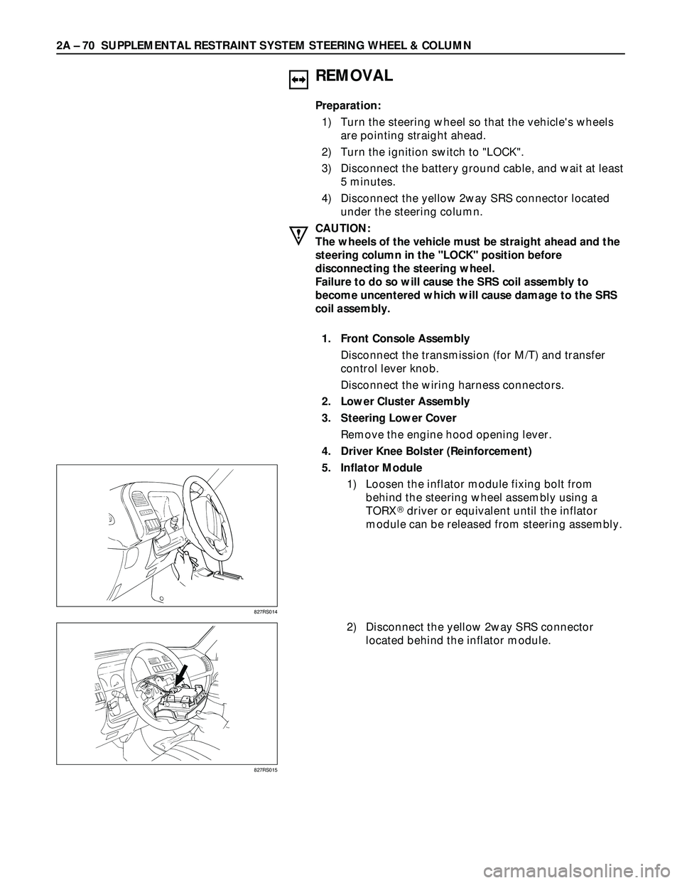
5. Inflator Module
1) Loosen the inflator module fixing bolt from
behind the steering wheel assembly using a
TORX
driver or equivalent until the inflator
module can be released from steering assembly.
2) Disconnect the yellow 2way SRS connector
located behind the inflator module.
827RS014
827RS015
Page 375 of 3573

SUPPLEMENTAL RESTRAINT SYSTEM STEERING WHEEL & COLUMN 2A Ð 73
Starter switch
harness
Combination
switch harness
Inflator module
harness
Setting cowl
(Lower)
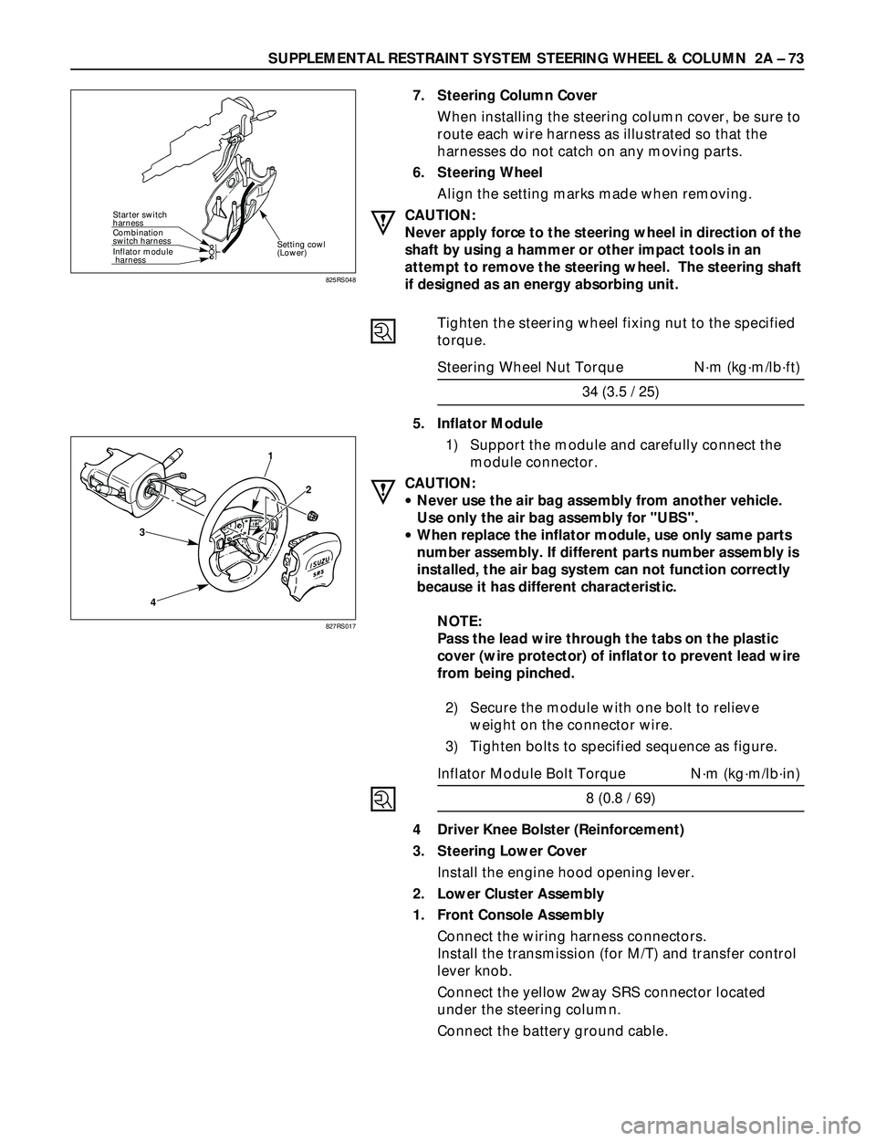
7. Steering Column Cover
When installing the steering column cover, be sure to
route each wire harness as illustrated so that the
harnesses do not catch on any moving parts.
6. Steering Wheel
Align the setting marks made when removing.
CAUTION:
Never apply force to the steering wheel in direction of the
shaft by using a hammer or other impact tools in an
attempt to remove the steering wheel. The steering shaft
if designed as an energy absorbing unit.
Tighten the steering wheel fixing nut to the specified
torque.
Steering Wheel Nut Torque Nám (kgám/lbáft)
34 (3.5 / 25)
5. Inflator Module
1) Support the module and carefully connect the
module connector.
CAUTION:
·Never use the air bag assembly from another vehicle.
Use only the air bag assembly for "UBS".
·When replace the inflator module, use only same parts
number assembly. If different parts number assembly is
installed, the air bag system can not function correctly
because it has different characteristic.
NOTE:
Pass the lead wire through the tabs on the plastic
cover (wire protector) of inflator to prevent lead wire
from being pinched.
2) Secure the module with one bolt to relieve
weight on the connector wire.
3) Tighten bolts to specified sequence as figure.
Inflator Module Bolt Torque Nám (kgám/lbáin)
8 (0.8 / 69)
4 Driver Knee Bolster (Reinforcement)
3. Steering Lower Cover
Install the engine hood opening lever.
2. Lower Cluster Assembly
1. Front Console Assembly
Connect the wiring harness connectors.
Install the transmission (for M/T) and transfer control
lever knob.
Connect the yellow 2way SRS connector located
under the steering column.
Connect the battery ground cable.
825RS048
3
41
2
827RS017