Page 2315 of 3573

DTC P1850 Brake Band Apply Solenoid Malfunction (Contd)
StepNo Ye s Action
23The wiring harness between the PCM connector terminal J1±A16
and the 16±w")
7A1±70
TRANSMISSION CONTROL SYSTEM (4L30±E)
DTC P1850 Brake Band Apply Solenoid Malfunction (Cont'd)
StepNo Ye s Action
23The wiring harness between the PCM connector terminal J1±A16
and the 16±way connector terminal H53±13 is open.
Was a problem found and corrected?
Go to Step 26Ð
24The wiring harness between the transmission 16±way connector
terminal H53±13 and the transmission main case connector
terminal M7±2(B) is open.
Was a problem found and corrected?
Go to Step 26Ð
25Check every connection at the PCM.
If OK, replace the PCM. Refer to Powertrain Control Module
(PCM) in Automatic Transmission (4L30±E) section.
Is the replacement complete?
Go to Step 26Ð
261. After the repair is complete, use the scan tool to select ªDTCº,
then ªClear Infoº function and ensure the following conditions
are met:
�The brake band apply solenoid is commanded ªonº and the
volts drop to zero.
�The brake band apply solenoid is commanded ªoffº and the
volts increase to B+.
2. Review the scan tool ªDTC Infoº.
Has the last test failed or is the current DTC displayed?
Begin diagnosis
again
Go to Step 1
Repair verified
Exit DTC table
Page 2318 of 3573
7A1±73
DTC P1860 TCC Solenoid Electrical (Contd)
StepNo Ye s Action
12The wiring harness between PCM connector terminal J2±D2 and
transmission 16±way connecto")
TRANSMISSION CONTROL SYSTEM (4L30±E)7A1±73
DTC P1860 TCC Solenoid Electrical (Cont'd)
StepNo Ye s Action
12The wiring harness between PCM connector terminal J2±D2 and
transmission 16±way connector terminal H53±8 is shorted to
ground.
Was a problem found and corrected?
Go to Step 20Ð
13The wiring harness between transmission 16±way connector
H±53 and adapter case connector M±6 is shorted to ground.
Was a problem found and corrected?
Go to Step 20Ð
14The TCC solenoid is faulty, or the internal wiring harness from the
TCC solenoid is shorted to ground.
Was a problem found and corrected?
Go to Step 20Ð
15The wiring harness between PCM connector terminal J2±D2 and
transmission 16±way connector terminal H53±8 is open.
Was a problem found and corrected?
Go to Step 20Ð
16The wiring harness between transmission 16±way connector
terminal H53±8 and adapter case terminal M6±4(A) is open.
Was a problem found and corrected?
Go to Step 20Ð
17The TCC solenoid is faulty, or the internal wiring harness from the
TCC solenoid is open.
Was a problem found and corrected?
Go to Step 20Ð
18Check every connection at the PCM.
If OK, replace the PCM. Refer to Powertrain Control Module
(PCM) in Automatic Transmission (4L30±E) section.
Is the replacement complete?
Go to Step 20Ð
19Check the PCM connector terminal J2±D2, transmission 16±way
connector terminal H53±8 and transmission adapter case
connector terminal M6±4(A).
Was a problem found and corrected?
Go to Step 20Ð
201. After the repair is complete, use the scan tool to select ªDTCº,
then ªClear Infoº function and ensure the following conditions
are met:
�The TCC solenoid is commanded ªonº and the volts increase
to B+.
�The TCC solenoid is commanded ªoffº and the volts drop to
zero.
2. Review the scan tool ªDTC Infoº.
Has the last test failed or is the current DTC displayed?
Begin diagnosis
again
Go to Step 1
Repair verified
Exit DTC table
Page 2604 of 3573

Anti-lock brake system
Assembly
Alternating")
WIRING SYSTEM 8DÐ11
Abbreviation Meaning of Abbreviation
A
ABS
ASM
AC
A/C
ACC
A/T
C/B
CSD
DIS
EBCM
ECGI
ECM
ECU
EFE
EGR
4A/T
4WD
FL
FRT
H/L
IC
IGAmpere (S)
Anti-lock brake system
Assembly
Alternating current
Air conditioner
Accessories
Automatic transmission
Circuit breaker
Cold start device
Direct ignition system
Electronic brake control module
Electronic control gasoline injection
Engine control module
Electronic control unit
Early fuel evaporation
Exhaust gas recirculation
4-speed automatic transmission
Four-wheel drive
Fusible link
Front
Headlight
Integrated circuit
IgnitionAbbreviation Meaning of Abbreviation
kW
LH
LWB
M/T
OD
OPT
PCM
QOS
RH
RR
SDM
SRS
ST
STD
SW
SWB
3A/T
V
VSV
W
WOT
W/
W/OKilowatt
Left hand
Long wheel base
Manual transmission
Over drive
Option
Powertrain control module
Quick on start
Right hand
Rear
Sensing and diagnostic module
Supplemental restraint system
Start
Standard
Switch
Short wheel base
3-speed automatic transmission
Volt
Vacuum switching valve
Watt (S)
Wide open throttle
With
Without
Abbreviations
Page 2673 of 3573

General Description
The Powertrain Control Module (PCM) is located in
the passenger compartment.
The PCM constantly monitors the information from
v")
8DÐ80 WIRING SYSTEM
Powertrain Control Module (PCM)
General Description
The Powertrain Control Module (PCM) is located in
the passenger compartment.
The PCM constantly monitors the information from
various sensors, and controls the systems that affect
vehicle performance.
The PCM performs the diagnostic function of the
system. It can recognize operational problems, alert
the driver through the Malfunction Indicator Light
(MIL) and store a Diagnostic Trouble Code (DTC) or
DTC(s) which identify the problem areas to aid the
technician in making repairs.
The PCM is designed to process the various input
informations and then sends the necessary
electrical responses to control fuel delivery, spark
timing and other emission control systems. The
input information has an interrelation to more than
one output, therefore, if the one input failed, it could
affect more than one system operation.
Refer to Driveability and Emission in Engine section
and Automatic Transmission in Transmission
section.
Page 3248 of 3573

8F±53 BODY STRUCTURE
Installation
To install, follow the removal steps in the reverse order.
Order Of Removal/Installation Steps For Each Item
Removal Item
Removal ProcedureRemoval Step
Front console assem-
blyShift knob (M/T), Power & Winter SW (A/T), Transfer knob, Seat
heater/Miller SW conn. and 4 screws1, 2
Lower cluster assem-
bly3 screws, Ciger lighter conn. and Ashtray illumination conn.1~3
Glove box2 screws4
Instrument panel pas-
senger lower cover7 screws and 1 clip1~5
Passenger knee bol-
ster reinforcement4 nuts and 4 bolts1~6
Instrument panel driver
lower coverEngine hood opening fixing screw, 2 screws, 1 bolt, 1 clip and fasten-
ers at 4 positions1~3, 7
Driver knee bolster6 nuts1~3, 7, 8
Front defroster grilleClaws at 8 positions9
Instrument panel as-
sembly2 bolts (SRS adjust bracket~ cross beam), A/C control cable (Unit
side at 3 position), Instrument harness connector (Driver side 5 posi-
tion, assist side 3 position), SRS module conn., Radio antenna jack,
Earth cable, 9 bolts and 3 nuts1~10
Passenger inflator
module4 nuts (SRS module~Instrument panel), 2 nuts 0 and 2 washers
(SRS module~support bracket) and 2 clips1~6, 11
Instrument panel clus-
ter5 Screws, fastener at 4 position and each SW conn.1~3, 7, 12
Meter assembly4 screws and connectors1~3, 7, 12, 13
A/C control panel as-
sembly4 screws and connectors1~3, 7, 12, 14
Radio assembly2 screws1~3, 15
Vent duct assembly5 screws1~10, 16
Instrument harness as-
sembly4 screws, fasteners at 4 position, and clips at 7 position1~10, 17
Side defroster grille18
M/T = Manual Transmission
A/T = Automatic Transmission
SRS = Supplemental Restraint System
A/C = Air Conditioning
Page 3559 of 3573
10A±8
CRUISE CONTROL SYSTEM
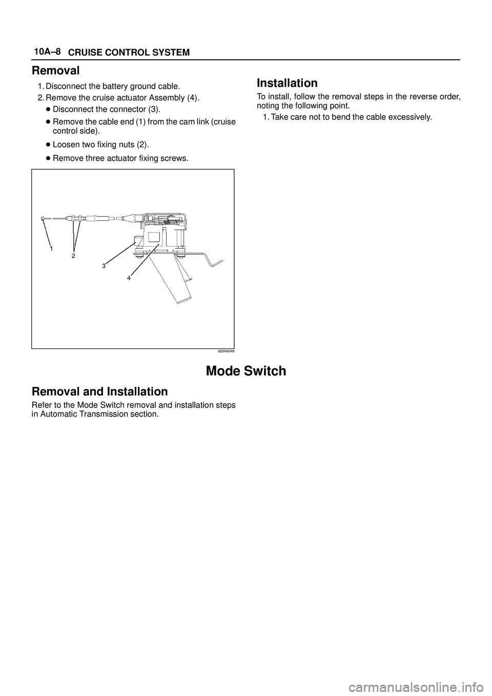
Removal
1. Disconnect the battery ground cable.
2. Remove the cruise actuator Assembly (4).
�Disconnect the connector (3).
�Remove the cable end (1) from the cam link (cruise
control side).
�Loosen two fixing nuts (2).
�Remove three actuator fixing screws.
825RW049
Installation
To install, follow the removal steps in the reverse order,
noting the following point.
1. Take care not to bend the cable excessively.
Mode Switch
Removal and Installation
Refer to the Mode Switch removal and installation steps
in Automatic Transmission section.
Page 3568 of 3573
PAGE BACK PAGE NEXT
THIS MALUAL INCLUDES THE FOLLOWING SECTIONS:
SECTION No. CONTRNTS
7A AUTOMATIC TRANSMISSION (4L30-E)
7A AUTOMATIC TRANSMISSION (AW30-40LE)
7A1 TRANSMISSION CONTROL SYSTEM (4L30-E)
7B MANUAL TRANSMISSION (AR-5)
7B MANUAL TRANSMISSION (MUA)
7C CLUTCH

7A AU")