Page 1510 of 3573

00 Ð 10 SERVICE INFORMATION
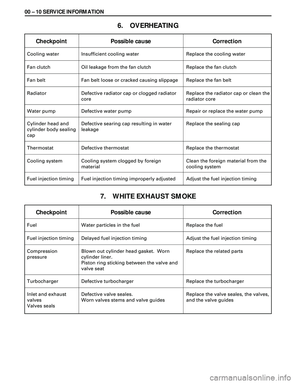
6. OVERHEATING
7. WHITE EXHAUST SMOKE
Checkpoint Possible cause Correction
Fuel Water particles in the fuel Replace the fuel
Fuel injection timing Delayed fuel injection timing Adjust the fuel injection timing
Compression
pressureBlown out cylinder head gasket. Worn
cylinder liner.
Piston ring sticking between the valve and
valve seatReplace the related parts
Turbocharger Defective turbocharger Replace the turbocharger
Inlet and exhaust
valves
Valves sealsDefective valve seales.
Worn valves stems and valve guidesReplace the valve seales, the valves,
and the valve guides
Checkpoint Possible cause Correction
Cooling water Insufficient cooling water Replace the cooling water
Fan clutch Oil leakage from the fan clutch Replace the fan clutch
Fan belt Fan belt loose or cracked causing slippage Replace the fan belt
Radiator Defective radiator cap or clogged radiator
coreReplace the radiator cap or clean the
radiator core
Water pump Defective water pump Repair or replace the water pump
Cylinder head and
cylinder body sealing
capDefective searing cap resulting in water
leakageReplace the sealing cap
Thermostat Defective thermostat Replace the thermostat
Cooling system Cooling system clogged by foreign
materialClean the foreign material from the
cooling system
Fuel injection timing Fuel injection timing improperly adjusted Adjust the fuel injection timing
Page 1517 of 3573
SERVICE INFORMATION 00 Ð 17
MAGNETIC SWITCH DOES NOT OPERATE THOUGH
STARTER SWITCH IS TURNED TO “START (ST)”
CHECK IF VOLTAGE IS PRESENT AT MAGNETIC
SWITCH TERMINAL “S” WHEN STARTER SWITCH
IS TURNED TO “START (ST)”
YESNO
CHECK IF INDICATOR LAMP ON
METER COMES ON NORMALLY
CHECK CONTINUITY
STARTER SWITCH AND
MAGNETIC SWITCH
TERMINAL “S”DISCONNECTION OR
FAULTY CONNECTION
BETWEEN BATTERY
AND STARTER SWITCH
YESNO
CHECK GROUND CABLE
YESNO
PINION
SLIDING
PART DOES
NOT MOVEMAGNETIC SWITCH
OR COIL IS
DISCONNECTED
OR BURNED OUT
REPAIR
REPAIR OR REPLACE STARTER
REPAIR
CHECK STARTER
RELAYFAULTY CONNECTION
OR STARTER SWITCH
CHECK CLUTCH
START SWITCHREPLACE STARTER
SWITCH
OR
Page 1518 of 3573
00 Ð 18 SERVICE INFORMATION
PINION MESHES WITH RING GEAR BUT
ENGINE DOES NOT RUN
CHECK GROUND CABLE
YESNO
REPAIR OR REPLACE
GROUND CABLE
FAULTY CONNECTION
OF BRUSH AND
COMMUTATORBURNED-OUT
MAGNETIC
STARTER SWITCHDISCONNECTION
OR DAMAGE OF
FIELD COILDISCONNECTION
OR DAMAGE OF
ARMATURE COILSLIP OF
PINION
CLUTCH
REPAIR OR REPLACE STARTER
Page 1614 of 3573
6A2Ð 12 4JG2-NA/4JG2-TURBO ENGINE
5. Air Conditioner (A/C) Compressor Assembly
·Remove A/C compressor fixng bolt (rear under
side of compressor) by using a long extension bar
at under side of wheel arch.
·Disconnect magnetic clutch harness connector.
·Removal fixing bolts (upper and front lower sides
of compressor) and set A/C compressor asm with
pipelines on battery cable.
6. Water Inlet Pipe: Turbo (4JG2-T Only)
7. Oil Feed Pipe: Turbo (4JG2-T Only)
·Remove joint bolt from turbo charger.
·Plug up oil port of turbocharger to prevent
entrance of foreign material.
8. Oil Return Pipe: Turbo (4JG2-T Only)
·Disconnect oil return pipe flange from
turbocharger.
9. Water Outlet Pipe: Turbo (4JG2-T Only)
10. Exh. Pipe: Ft (4JG2-T Only)
11. Heat Protector (4JG2-T Only)
12. Exh. Adapter (4JG2-T Only)
13. Turbocharger Assembly (4JG2-T Only)
·Remove turbocharger asm from exhaust
manifold.
Page 1629 of 3573

4JG2-NA/4JG2-TURBO ENGINE 6A 2Ð 27
REMOVAL
Preparation
·Remove battery. (two batteries for cold area)
·Disconnect window washer hose, and remove
engine hood.
·Drain coolant.
·Space stand and front right tire.
1. Radiator Hose : Upper
·Disconnect upper radiator hose from engine side.
2. Air Cleaner Cover & Air Duct
3. Intercooler Assembly (4JG2-T Only)
·(Refer to intercooler removal steps in this section)
4. Oil Level Gauge Guide Tube
5. P/S Pump
·Loosen P/S pump fixing bolts and adjusting bolt
and remove two drive belts.
·Remove two fixing bolts (front side). A fixing nut
(rear side) and support P/S pump asm with oil
hoses by tying to body side.
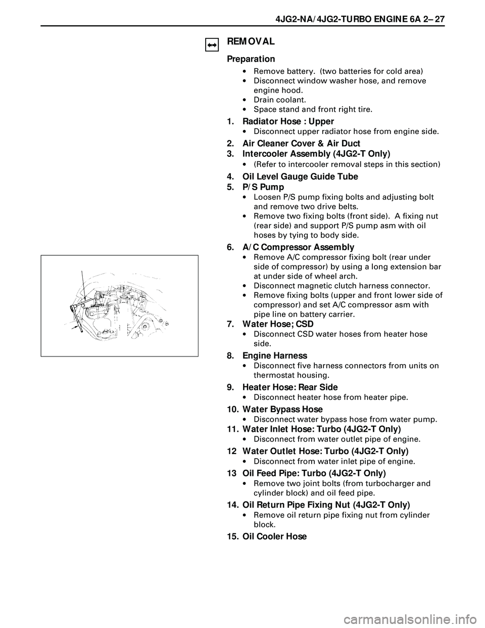
6. A/C Compressor Assembly
·Remove A/C compressor fixing bolt (rear under
side of compressor) by using a long extension bar
at under side of wheel arch.
·Disconnect magnetic clutch harness connector.
·Remove fixing bolts (upper and front lower side of
compressor) and set A/C compressor asm with
pipe line on battery carrier.
7. Water Hose; CSD
·Disconnect CSD water hoses from heater hose
side.
8. Engine Harness
·Disconnect five harness connectors from units on
thermostat housing.
9. Heater Hose: Rear Side
·Disconnect heater hose from heater pipe.
10. Water Bypass Hose
·Disconnect water bypass hose from water pump.
11. Water Inlet Hose: Turbo (4JG2-T Only)
·Disconnect from water outlet pipe of engine.
12 Water Outlet Hose: Turbo (4JG2-T Only)
·Disconnect from water inlet pipe of engine.
13 Oil Feed Pipe: Turbo (4JG2-T Only)
·Remove two joint bolts (from turbocharger and
cylinder block) and oil feed pipe.
14. Oil Return Pipe Fixing Nut (4JG2-T Only)
·Remove oil return pipe fixing nut from cylinder
block.
15. Oil Cooler Hose
Page 1651 of 3573

4JG2-NA/4JG2-TURBO ENGINE 6A2 Ð 49
3. Cooling Fan Assembly
·Remove cooling fan asm fixing nuts, cooling fan
asm, fan pulley and center.
4. Radiator Assembly
·Remove bracket and radiator asm.
5. Air Cleaner Cover & Air Duct
6. Intercooler Assembly (4JG2 -T only)
·(Refer to Intercooler removal steps in this section)
7. P/S Pump Drive Belts
·Loosen P/S pump fixing bolts and adjusting bolt
and remove two drive belts.
8. P/S Pump Assembly
·Remove two fixing bolts (front side), a fixing nut
(rear side) and support P/S pump asm with oil
hoses by tying to body side.
9. Engine Ground Cable
·Disconnect ground cable from A/C compressor
bracket.
10. AC Generator Harness
·Disconnect B terminal and harness connector
from AC generator.
11. A/C Compressor Assembly
·Remove A/C compressor fixing bolt (rear under
side of compressor) by using a long extension bar
at under side of wheel arch.
·Disconnect magnetic clutch harness connector.
·Remove fixing bolts (upper and front lower side
of compressor) and set A/C compressor asm with
pipe lines on battery carrier.
12. Vacuum Hose: Vacuum Pump
·Disconnect vacuum hose from vacuum pump.
13. Starter Harness
·Disconnect B terminal and put cable harness close
to chassis side.
·Disconnect S terminal connector.
14. Engine Harness.
·Disconnect engine harness close to engine side.
15. Accelerater Cable
·Loosen locking nut at bracket and disconnect
accelerater cable from injection pump control
lever.
16. Fuel Hoses
·Disconnect fuel hoses from injection pump side
and take care not to spill fuel and enter dust.
17. Engine Ground Cable
·Disconnect ground cable from left rear side of
timing gear case.
Page 1697 of 3573
STARTING SYSTEM 6D2 Ð 3
ON-VEHICLE SERVICE
STARTER
REMOVAL
Preparation
·Battery ground cable (both batteries)
1. Oil Level Gauge and Guide
·Remove the guide and plug the hole on the oil pan.
2. Clutch Slave Cylinder
·Remove the slave cylinder and wire it to the frame.
3. Starter Wiring Connector
·Disconnect the connector from terminals ÒBÓ and
ÒSÓ.
4. Mounting
5. Starter Assembly
Page 1698 of 3573
6D2 Ð 4 STARTING SYSTEM
INSTALLATION
To install, follow the removal steps in the reverse order.
5. Starter Assembly
¥
Tighten the fixing bolt and nut to the
specified torque
4. Mounting
3. Starter Wiring Connector
·Reconnect the connectors to terminals ÒBÓ and
ÒSÓ.
2. Clutch Slave Cylinder
¥
Tighten the fixing bolt and nut to the
specified torque
78 (8.0/58)
N·m (Kg·m/lb·ft)
1. Oil Level Gauge and Guide
·Connect the battery ground cable.94 (9.6/69)
N·m (Kg·m/lb·ft)