1998 ISUZU TROOPER clutch
[x] Cancel search: clutchPage 1700 of 3573
6D2 Ð 6 STARTING SYSTEM
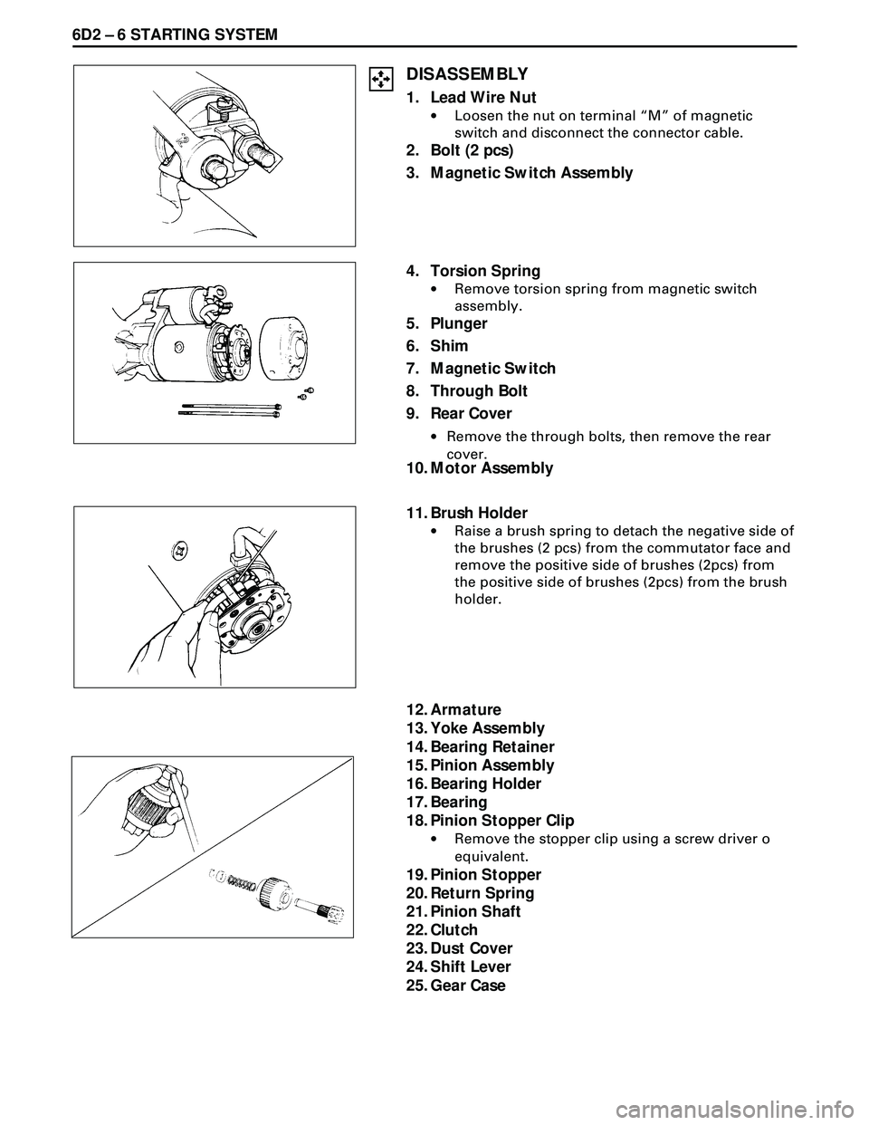
DISASSEMBLY
1. Lead Wire Nut
·Loosen the nut on terminal ÒMÓ of magnetic
switch and disconnect the connector cable.
2. Bolt (2 pcs)
3. Magnetic Switch Assembly
10. Motor Assembly
11. Brush Holder
·Raise a brush spring to detach the negative side of
the brushes (2 pcs) from the commutator face and
remove the positive side of brushes (2pcs) from
the positive side of brushes (2pcs) from the brush
holder.
4. Torsion Spring
·Remove torsion spring from magnetic switch
assembly.
5. Plunger
6. Shim
7. Magnetic Switch
8. Through Bolt
9. Rear Cover
·Remove the through bolts, then remove the rear
cover.
12. Armature
13. Yoke Assembly
14. Bearing Retainer
15. Pinion Assembly
16. Bearing Holder
17. Bearing
18. Pinion Stopper Clip
·Remove the stopper clip using a screw driver o
equivalent.
19. Pinion Stopper
20. Return Spring
21. Pinion Shaft
22. Clutch
23. Dust Cover
24. Shift Lever
25. Gear Case
Page 1761 of 3573
6A – 28 ENGINE MECHANICAL
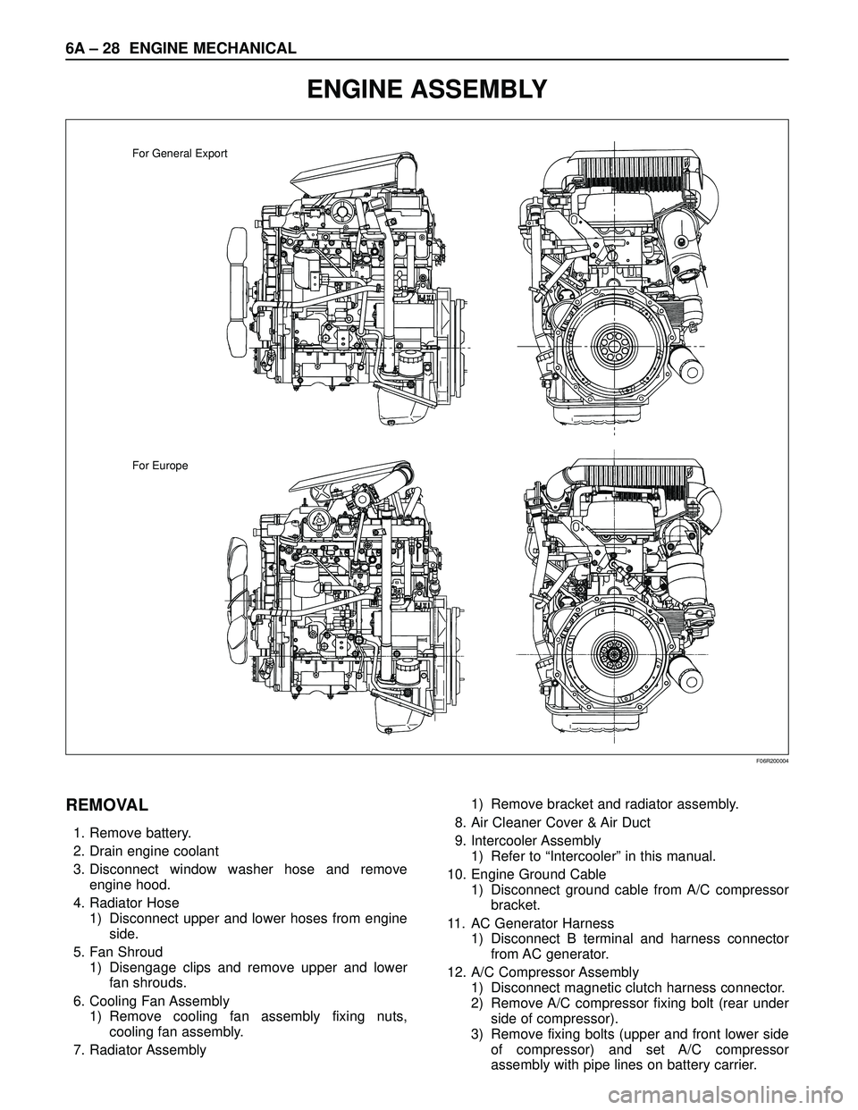
ENGINE ASSEMBLY
For General Export
For Europe
F06R200004
REMOVAL
1. Remove battery.
2. Drain engine coolant
3. Disconnect window washer hose and remove
engine hood.
4. Radiator Hose
1) Disconnect upper and lower hoses from engine
side.
5. Fan Shroud
1) Disengage clips and remove upper and lower
fan shrouds.
6. Cooling Fan Assembly
1) Remove cooling fan assembly fixing nuts,
cooling fan assembly.
7. Radiator Assembly1) Remove bracket and radiator assembly.
8. Air Cleaner Cover & Air Duct
9. Intercooler Assembly
1) Refer to “Intercooler” in this manual.
10. Engine Ground Cable
1) Disconnect ground cable from A/C compressor
bracket.
11. AC Generator Harness
1) Disconnect B terminal and harness connector
from AC generator.
12. A/C Compressor Assembly
1) Disconnect magnetic clutch harness connector.
2) Remove A/C compressor fixing bolt (rear under
side of compressor).
3) Remove fixing bolts (upper and front lower side
of compressor) and set A/C compressor
assembly with pipe lines on battery carrier.
Page 1839 of 3573
6B – 6 ENGINE COOLING
REMOVAL
1. Drain coolant.
2. AC Generator Drive Belt
1) Loosen AC Generator mounting bolt, adjust
plate lock bolt, and remove the drive belt.
3. Cooling Fan Assembly
1) Remove lock nut and take out cooling fan
assembly with cooling fan clutch.
4. Water Pump Assembly
INSPECTION
Make necessary repair and parts replacement if
excessive wear or damage is found during inspection.
Should any of the following problems occur, the entire
water pump assembly must be replaced.
1) Cracks in the water pump body
2) Coolant leakage from the seal unit
3) Excessive play in radial direction or abnormal noise
4) Excessive play in thrust direction
Limit : 0.2mm (0.008in) or less
5) Cracks or corrosion in the impeller
INSTALLATION
1. Gasket
1) Set gasket to gear case.
2. Water Pump Assembly
1) Install water pump assembly, and tighten to
specified torque.Torque: 20 N·m (2.0 kg·m/14.5 lb ft)
3. Cooling Fan Assembly
1) Install cooling fan assembly, and tighten to
specified torque.
Torque: 8 N·m (0.8 kg·m/5.8 lb ft)
4. AC Generator Drive Belt
1) Install AC Generator drive belt and adjust belt
tension.
Torque: 40 N·m (4.1 kg·m/29.7 lb ft)
For ACG to bracket
20 N·m (2.0 kg·m/14.5 lb ft)
For ACG to adjust plate
5. Fill coolant to specified capacity.
12
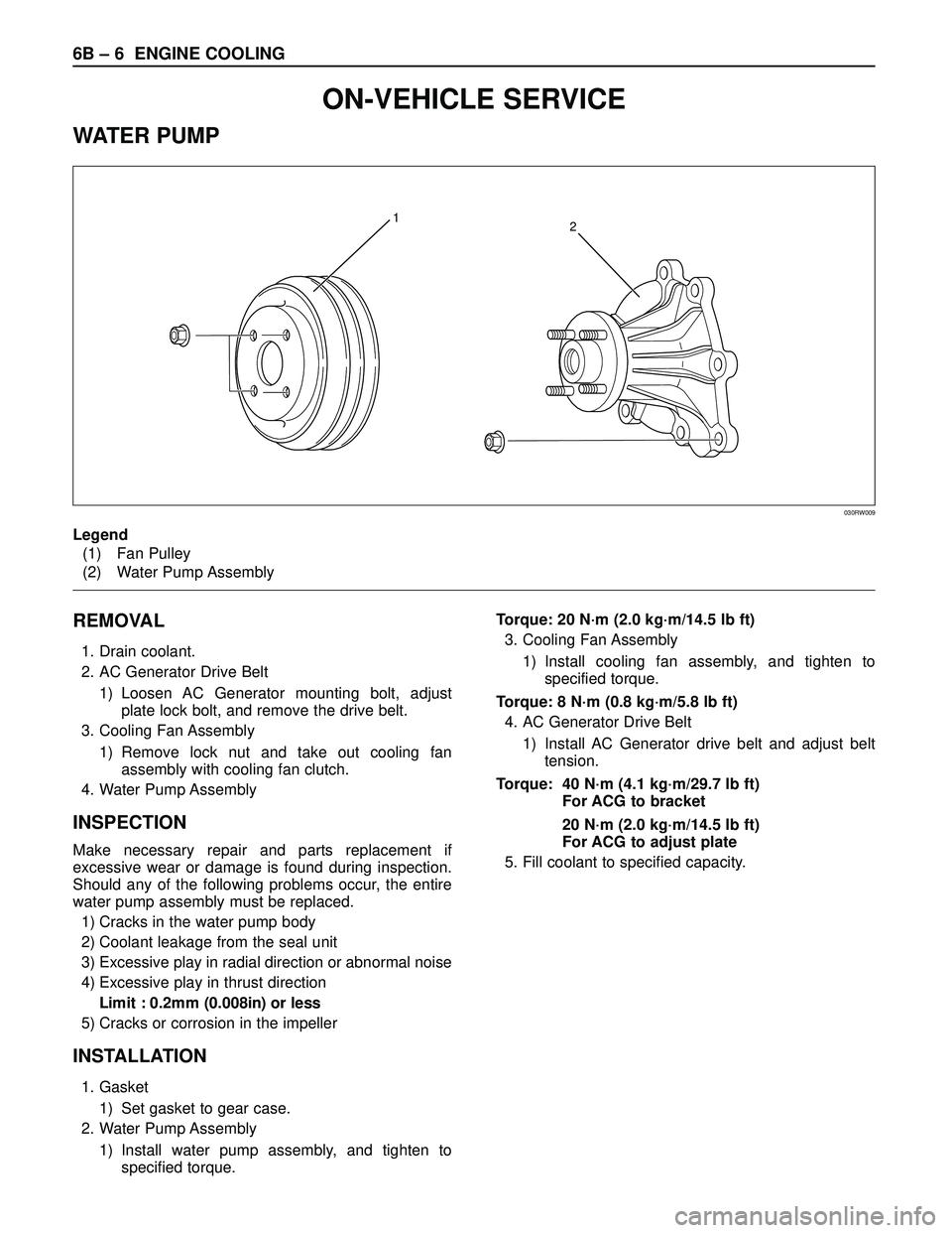
Legend
(1) Fan Pulley
(2) Water Pump Assembly
030RW009
ON-VEHICLE SERVICE
WATER PUMP
Page 1872 of 3573
ENGINE ELECTRICAL 6D – 5
STARTING SYTEM
GENERAL DESCRIPTION
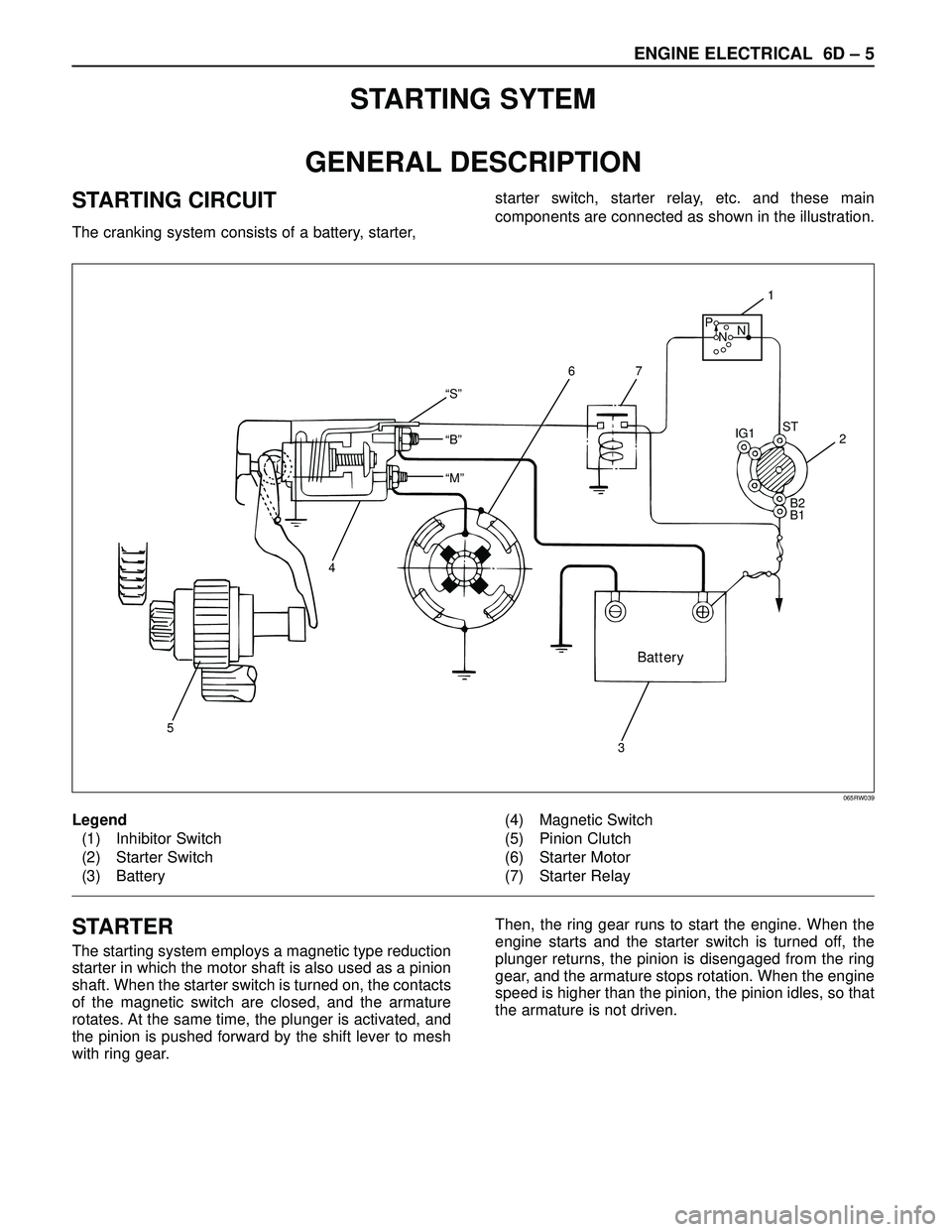
STARTING CIRCUIT
The cranking system consists of a battery, starter, starter switch, starter relay, etc. and these main
components are connected as shown in the illustration.
“S”
“B”
“M”
Battery
5
4
32 IG1ST
B2
B1
1
76
P
NN
Legend
(1) Inhibitor Switch
(2) Starter Switch
(3) Battery(4) Magnetic Switch
(5) Pinion Clutch
(6) Starter Motor
(7) Starter Relay
065RW039
STARTER
The starting system employs a magnetic type reduction
starter in which the motor shaft is also used as a pinion
shaft. When the starter switch is turned on, the contacts
of the magnetic switch are closed, and the armature
rotates. At the same time, the plunger is activated, and
the pinion is pushed forward by the shift lever to mesh
with ring gear.Then, the ring gear runs to start the engine. When the
engine starts and the starter switch is turned off, the
plunger returns, the pinion is disengaged from the ring
gear, and the armature stops rotation. When the engine
speed is higher than the pinion, the pinion idles, so that
the armature is not driven.
Page 1874 of 3573
ENGINE ELECTRICAL 6D – 7
ON-VEHICLE SERVICE
STARTER
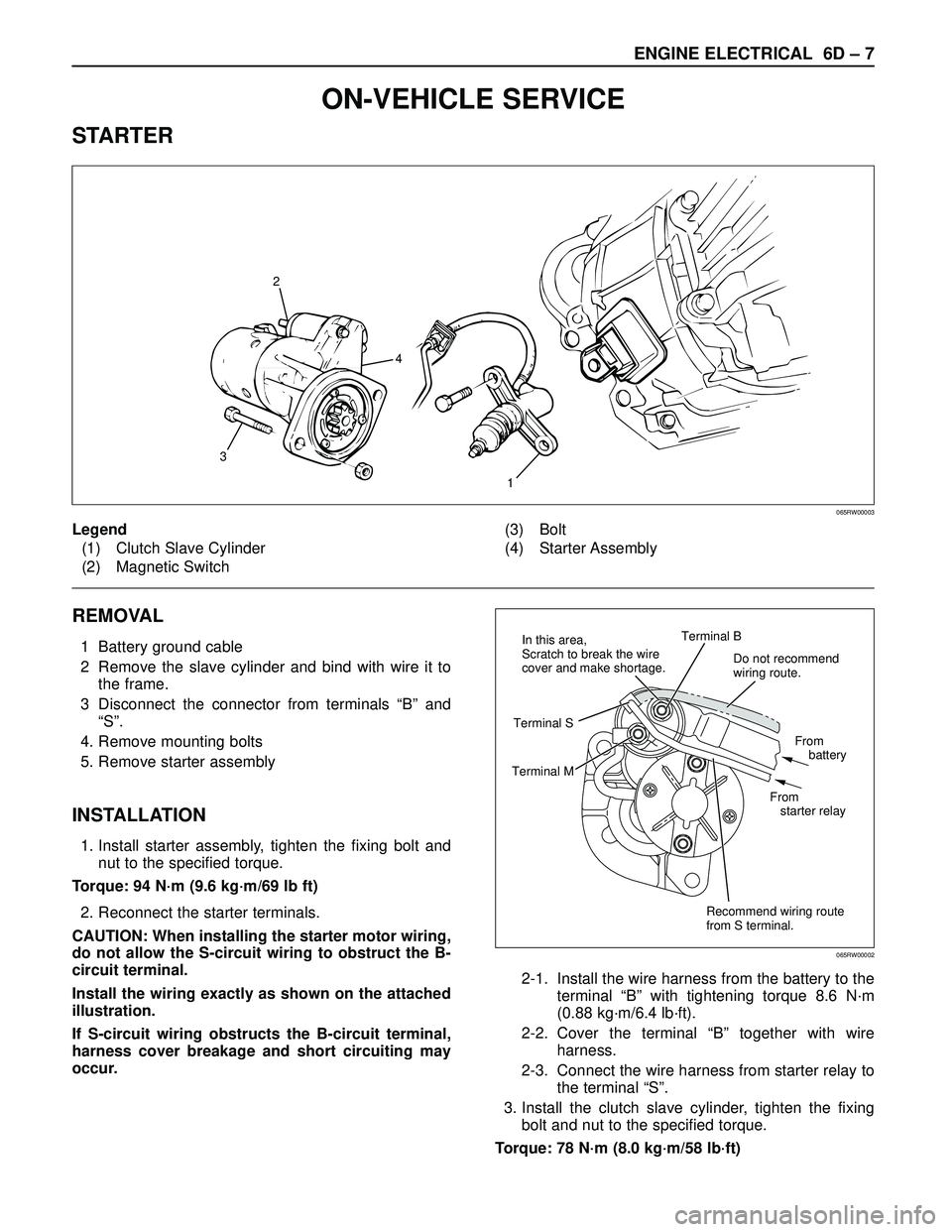
REMOVAL
1 Battery ground cable
2 Remove the slave cylinder and bind with wire it to
the frame.
3 Disconnect the connector from terminals “B” and
“S”.
4. Remove mounting bolts
5. Remove starter assembly
INSTALLATION
1. Install starter assembly, tighten the fixing bolt and
nut to the specified torque.
Torque: 94 N·m (9.6 kg·m/69 lb ft)
2. Reconnect the starter terminals.
CAUTION: When installing the starter motor wiring,
do not allow the S-circuit wiring to obstruct the B-
circuit terminal.
Install the wiring exactly as shown on the attached
illustration.
If S-circuit wiring obstructs the B-circuit terminal,
harness cover breakage and short circuiting may
occur.2-1. Install the wire harness from the battery to the
terminal “B” with tightening torque 8.6 N·m
(0.88 kg·m/6.4 lb·ft).
2-2. Cover the terminal “B” together with wire
harness.
2-3. Connect the wire harness from starter relay to
the terminal “S”.
3. Install the clutch slave cylinder, tighten the fixing
bolt and nut to the specified torque.
Torque: 78 N·m (8.0 kg·m/58 lb·ft)
1
32
4
Legend
(1) Clutch Slave Cylinder
(2) Magnetic Switch(3) Bolt
(4) Starter Assembly
065RW00003
Do not recommend
wiring route.
Recommend wiring route
from S terminal.From
battery
From
starter relay Terminal B
Terminal MTerminal SIn this area,
Scratch to break the wire
cover and make shortage.
065RW00002
Page 1875 of 3573
6D – 8 ENGINE ELECTRICAL
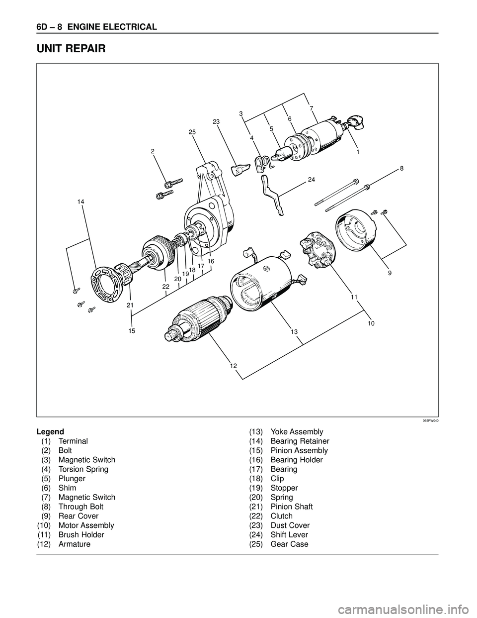
UNIT REPAIR
8
241 3
23
25
2
14
15 21222019181716
109
11
13
127
6
5
4
Legend
(1) Terminal
(2) Bolt
(3) Magnetic Switch
(4) Torsion Spring
(5) Plunger
(6) Shim
(7) Magnetic Switch
(8) Through Bolt
(9) Rear Cover
(10) Motor Assembly
(11) Brush Holder
(12) Armature(13) Yoke Assembly
(14) Bearing Retainer
(15) Pinion Assembly
(16) Bearing Holder
(17) Bearing
(18) Clip
(19) Stopper
(20) Spring
(21) Pinion Shaft
(22) Clutch
(23) Dust Cover
(24) Shift Lever
(25) Gear Case
065RW040
Page 1876 of 3573
ENGINE ELECTRICAL 6D – 9
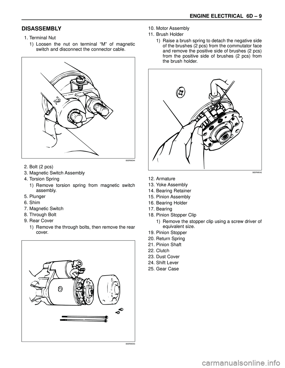
DISASSEMBLY
1. Terminal Nut
1) Loosen the nut on terminal “M” of magnetic
switch and disconnect the connector cable.
2. Bolt (2 pcs)
3. Magnetic Switch Assembly
4. Torsion Spring
1) Remove torsion spring from magnetic switch
assembly.
5. Plunger
6. Shim
7. Magnetic Switch
8. Through Bolt
9. Rear Cover
1) Remove the through bolts, then remove the rear
cover.10. Motor Assembly
11. Brush Holder
1) Raise a brush spring to detach the negative side
of the brushes (2 pcs) from the commutator face
and remove the positive side of brushes (2 pcs)
from the positive side of brushes (2 pcs) from
the brush holder.
12. Armature
13. Yoke Assembly
14. Bearing Retainer
15. Pinion Assembly
16. Bearing Holder
17. Bearing
18. Pinion Stopper Clip
1) Remove the stopper clip using a screw driver of
equivalent size.
19. Pinion Stopper
20. Return Spring
21. Pinion Shaft
22. Clutch
23. Dust Cover
24. Shift Lever
25. Gear Case
065RW044
065RW043
065RW042
Page 1899 of 3573
6E±6
4JX1±TC ENGINE DRIVEABILITY AND EMISSIONS
Removal Procedure 6E±212. . . . . . . . . . . . . . . . . . . .
Installation Procedure 6E±212. . . . . . . . . . . . . . . . . .
Fuel Filter Cap 6E±213. . . . . . . . . . . . . . . . . . . . . . . . . .
General Description 6E±213. . . . . . . . . . . . . . . . . . . .
Inspection Procedure 6E±213. . . . . . . . . . . . . . . . . .
Fuel Filter 6E±213. . . . . . . . . . . . . . . . . . . . . . . . . . . . . .
Removal and Installation Procedure 6E±213. . . . . .
Fuel Gauge Unit 6E±213. . . . . . . . . . . . . . . . . . . . . . . .
Removal Procedure 6E±213. . . . . . . . . . . . . . . . . . . .
Installation Procedure 6E±214. . . . . . . . . . . . . . . . . .
Fuel Injectors 6E±214. . . . . . . . . . . . . . . . . . . . . . . . . . .
Removal and Installation Procedure 6E±214. . . . . .
Fuel Temperature Sensor 6E±214. . . . . . . . . . . . . . . .
Removal Procedure 6E±214. . . . . . . . . . . . . . . . . . . .
Installation Procedure 6E±215. . . . . . . . . . . . . . . . . .
Rail Pressure (RP) Sensor 6E±216. . . . . . . . . . . . . . .
Removal Procedure 6E±216. . . . . . . . . . . . . . . . . . . .
Installation Procedure 6E±216. . . . . . . . . . . . . . . . . .
Fuel Tank 6E±216. . . . . . . . . . . . . . . . . . . . . . . . . . . . . .
Removal Procedure 6E±216. . . . . . . . . . . . . . . . . . . .
Throttle Body (TB) 6E±217. . . . . . . . . . . . . . . . . . . . . . .
Removal Procedure 6E±217. . . . . . . . . . . . . . . . . . . .
Installation Procedure 6E±217. . . . . . . . . . . . . . . . . .
Air Conditioning (A/C) Relay 6E±217. . . . . . . . . . . . . .
Removal Procedure 6E±217. . . . . . . . . . . . . . . . . . . .
Installation Procedure 6E±217. . . . . . . . . . . . . . . . . .
Exhaust Gas Recirculation (EGR) Vacuum
Switch Valve (VSV) 6E±217. . . . . . . . . . . . . . . . . . . . .
Removal Procedure 6E±217. . . . . . . . . . . . . . . . . . . .
Installation Procedure 6E±218. . . . . . . . . . . . . . . . . .
Electronic Vacuum Regurating Valve (EVRV) 6E±219
Removal Procedure 6E±219. . . . . . . . . . . . . . . . . . . .
Installation Procedure 6E±220. . . . . . . . . . . . . . . . . .
Wiring and Connectors 6E±220. . . . . . . . . . . . . . . . . . .
Wiring Harness Service 6E±220. . . . . . . . . . . . . . . .
Connectors and Terminals 6E±220. . . . . . . . . . . . . .
Wire Harness Repair: Twisted Shielded
Cable 6E±220. . . . . . . . . . . . . . . . . . . . . . . . . . . . . . . . .
Removal Procedure 6E±220. . . . . . . . . . . . . . . . . . . .
Installation Procedure 6E±221. . . . . . . . . . . . . . . . . .
Twisted Leads 6E±221. . . . . . . . . . . . . . . . . . . . . . . . . .
Removal Procedure 6E±221. . . . . . . . . . . . . . . . . . . .
Installation Procedure 6E±222. . . . . . . . . . . . . . . . . .
Weather-Pack Connector 6E±223. . . . . . . . . . . . . . . . .
Tools Required 6E±223. . . . . . . . . . . . . . . . . . . . . . . .
Removal Procedure 6E±223. . . . . . . . . . . . . . . . . . . . Installation Procedure 6E±223. . . . . . . . . . . . . . . . . .
Com-Pack III 6E±224. . . . . . . . . . . . . . . . . . . . . . . . . . .
General Information 6E±224. . . . . . . . . . . . . . . . . . . .
Metri-Pack 6E±224. . . . . . . . . . . . . . . . . . . . . . . . . . . . .
Tools Required 6E±224. . . . . . . . . . . . . . . . . . . . . . . .
Removal Procedure 6E±224. . . . . . . . . . . . . . . . . . . .
Installation Procedure 6E±224. . . . . . . . . . . . . . . . . .
General Description
(ECM and Sensors) 6E±225. . . . . . . . . . . . . . . . . . . . .
57X Reference ECM Input 6E±225. . . . . . . . . . . . . .
A/C Request Signal 6E±225. . . . . . . . . . . . . . . . . . . .
Crankshaft Position (CKP) Sensor 6E±225. . . . . . .
Camshaft Position (CMP) Sensor and
Signal 6E±225. . . . . . . . . . . . . . . . . . . . . . . . . . . . . . .
Engine Coolant Temperature (ECT) Sensor 6E±225
Electrically Erasable Programmable Read
Only Memory (EEPROM) 6E±225. . . . . . . . . . . . . .
Intake Air Temperature (IAT) Sensor 6E±225. . . . .
Manifold Absolute Pressure (MAP) Sensor 6E±226
Engine Control Module (ECM) 6E±226. . . . . . . . . . .
ECM Function 6E±226. . . . . . . . . . . . . . . . . . . . . . . . .
ECM Components 6E±226. . . . . . . . . . . . . . . . . . . . .
ECM Voltage Description 6E±226. . . . . . . . . . . . . . .
ECM Input/Outputs 6E±226. . . . . . . . . . . . . . . . . . . .
ECM Service Precautions 6E±227. . . . . . . . . . . . . .
Intake Throttle Position (ITP) Sensor 6E±227. . . . .
Transmission Range Switch 6E±227. . . . . . . . . . . . .
Accelerator Position Sensor (AP) 6E±227. . . . . . . .
Aftermarket Electrical and Vacuum
Equipment 6E±227. . . . . . . . . . . . . . . . . . . . . . . . . . .
Electrostatic Discharge Damage 6E±227. . . . . . . . .
General Description (Air Induction) 6E±228. . . . . . . .
Air Induction System 6E±228. . . . . . . . . . . . . . . . . . .
General Description (Fuel Metering) 6E±228. . . . . . .
Deceleration Mode 6E±228. . . . . . . . . . . . . . . . . . . .
Fuel Injector 6E±228. . . . . . . . . . . . . . . . . . . . . . . . . .
Fuel Metering System Components 6E±228. . . . . .
A/C Clutch Diagnosis 6E±228. . . . . . . . . . . . . . . . . . . .
A/C Request Signal 6E±228. . . . . . . . . . . . . . . . . . . .
General Description Exhaust Gas
Recirculation (EGR) System 6E±228. . . . . . . . . . . . .
EGR Purpose 6E±228. . . . . . . . . . . . . . . . . . . . . . . . .
Fuse and Relay Panel
(Underhood Electrical Center) RHD 6E±229. . . . . . .
Fuse and Relay Panel
(Underhood Electrical Center) LHD 6E±230. . . . . . .