Page 2188 of 3573

7A±34
AUTOMATIC TRANSMISSION (4L30±E)
5. Install the flywheel under cover (3 pieces), and tighten
the bolts to the specified torque.
Torque: 8 Nwm (0.8 kg´m/69 lb in)
6. Install the starter, and tighten the bolts to the specified
torque.
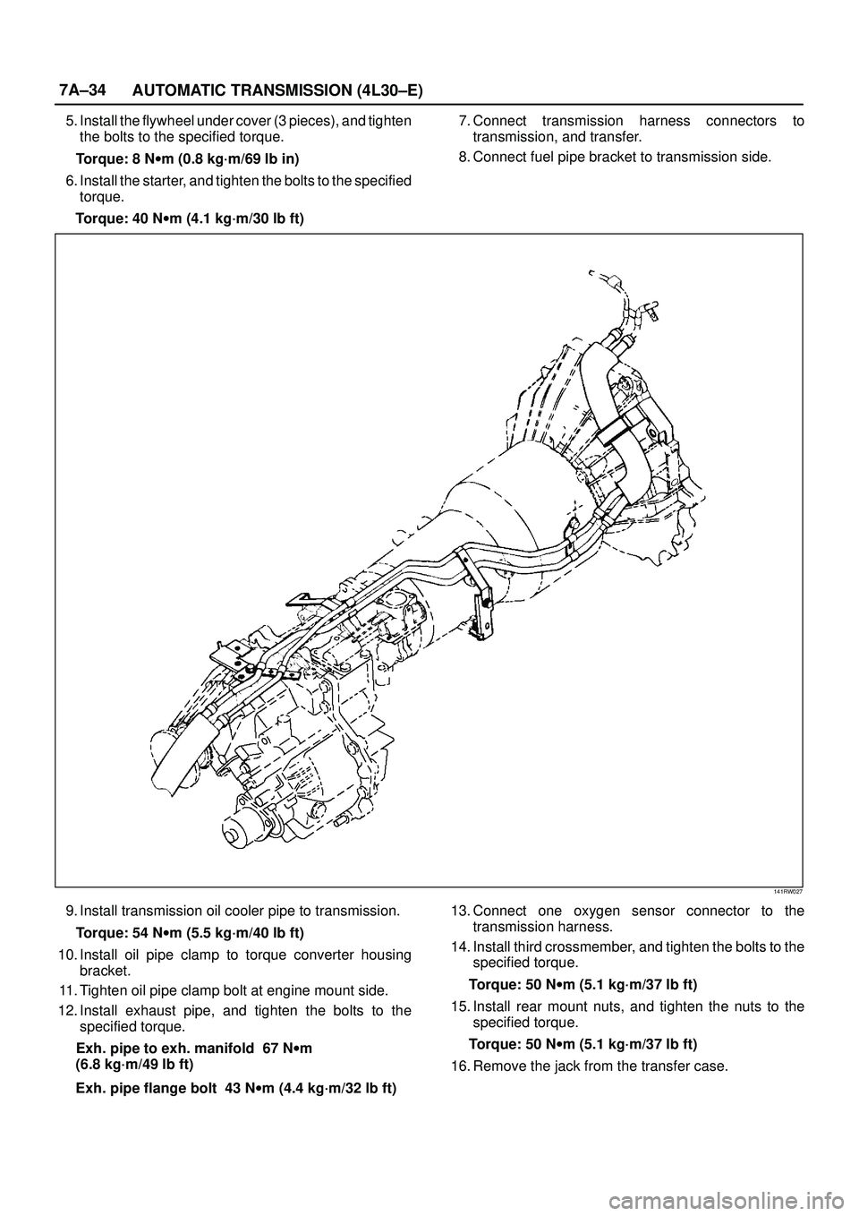
Torque: 40 Nwm (4.1 kg´m/30 lb ft)7. Connect transmission harness connectors to
transmission, and transfer.
8. Connect fuel pipe bracket to transmission side.
141RW027
9. Install transmission oil cooler pipe to transmission.
Torque: 54 Nwm (5.5 kg´m/40 lb ft)
10. Install oil pipe clamp to torque converter housing
bracket.
11. Tighten oil pipe clamp bolt at engine mount side.
12. Install exhaust pipe, and tighten the bolts to the
specified torque.
Exh. pipe to exh. manifold 67 Nwm
(6.8 kg´m/49 lb ft)
Exh. pipe flange bolt 43 Nwm (4.4 kg´m/32 lb ft)13. Connect one oxygen sensor connector to the
transmission harness.
14. Install third crossmember, and tighten the bolts to the
specified torque.
Torque: 50 Nwm (5.1 kg´m/37 lb ft)
15. Install rear mount nuts, and tighten the nuts to the
specified torque.
Torque: 50 Nwm (5.1 kg´m/37 lb ft)
16. Remove the jack from the transfer case.
Page 2327 of 3573
MANUAL TRANSMISSION7B±9
16. Remove the slave cylinder heat protector.
17. Remove the harness heat protector (6VE1).
(6VE1)
225RW006
18. Remove two transmission harness clamps and
bracket (6VE1).
19. Remove the slave cylinder.
206RW002
20. Remove the two dust cover from transmission case.
21. Support the transfer case with a jack.22. Remove two engine rear mount nuts.
(6VE1)
022RT002
23. Remove third crossmember (6VE1).
24. Remove third crossmember with rear mount rubber
(4JX1).
(4JX1)
022RW013
25. Remove two engine rear mount bolts (6VE1).
26. Remove the rear mount from the transmission
(6VE1).
27. Remove three flywheel under cover (6VE1).
Page 2519 of 3573
7C±10CLUTCH
5. Mark the flywheel, clutch cover and pressure plate lug
for alignment when installing.
6. Remove the release bearing (3) from the
transmission case .
7. Remove the shift fork snap pin.
8. Remove the shift fork pin and shift fork (4) from the
front cover.
9. Remove the front cover bolts.
10. Remove the front cover (5) from the transmission
case.
220RW088
11. Remove flywheel assembly and crankshaft bearing.
Do not remove except for replacement.
12. Use the remover 5±8840±2000±0 (J±5822) and
sliding hammer 5±8840±0019±0 (J±23907) to
remove the crankshaft bearing
015RW053
Inspection and Repair
Make necessary correction or parts replacement if wear,
damage, or any other abnormal condition are found
through inspection.
Pressure Plate Assembly
201RS002
1. Visually check the pressure plate friction surface for
excessive wear and heat cracks.
2. If excessive wear or deep heat cracks are present,
the pressure plate must be replaced.
Pressure Plate Warpage
201RS003
Page 2520 of 3573

CLUTCH7C±11
1. Use a straight edge and a feeler gauge to measure
the pressure plate friction surface flatness in four
directions.
2. If any of the measured values exceeds the specified
limit, the pressure plate must be replaced.
Pressure Plate Warpage
Limit: 0.3 mm (0.012 in)
Clutch Cover
201RS004
1. Visually check the entire clutch cover for excessive
wear, cracking, and other damage.
2. The clutch cover must be replaced if any of these
conditions are present.
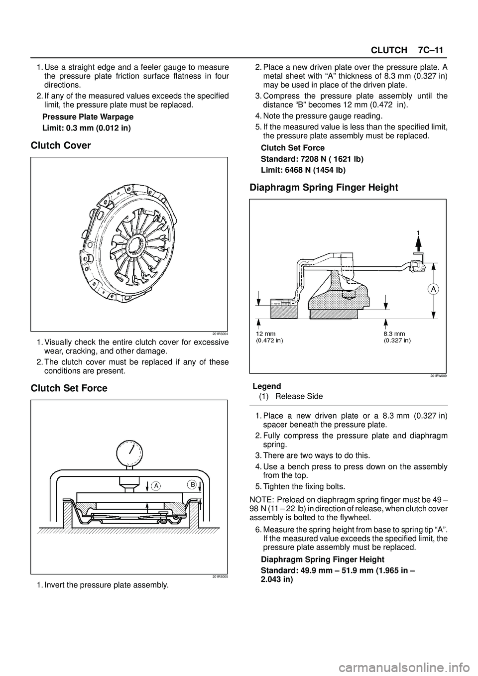
Clutch Set Force
201RS005
1. Invert the pressure plate assembly.2. Place a new driven plate over the pressure plate. A
metal sheet with ªAº thickness of 8.3 mm (0.327 in)
may be used in place of the driven plate.
3. Compress the pressure plate assembly until the
distance ªBº becomes 12 mm (0.472 in).
4. Note the pressure gauge reading.
5. If the measured value is less than the specified limit,
the pressure plate assembly must be replaced.
Clutch Set Force
Standard: 7208 N ( 1621 lb)
Limit: 6468 N (1454 lb)
Diaphragm Spring Finger Height
201RW009
Legend
(1) Release Side
1. Place a new driven plate or a 8.3 mm (0.327 in)
spacer beneath the pressure plate.
2. Fully compress the pressure plate and diaphragm
spring.
3. There are two ways to do this.
4. Use a bench press to press down on the assembly
from the top.
5. Tighten the fixing bolts.
NOTE: Preload on diaphragm spring finger must be 49 ±
98 N (11 ± 22 lb) in direction of release, when clutch cover
assembly is bolted to the flywheel.
6. Measure the spring height from base to spring tip ªAº.
If the measured value exceeds the specified limit, the
pressure plate assembly must be replaced.
Diaphragm Spring Finger Height
Standard: 49.9 mm ± 51.9 mm (1.965 in ±
2.043 in)
Page 2524 of 3573

CLUTCH7C±15
Installation
To install, follow the removal steps in the reverse order,
noting the following points:
1. Install flywheel assembly and crankshaft bearing.
Use the installer 5-8840-0125-0 (J-26516-A) and
driver handle 5-8840-0007-0 (J-8092) to install the
crankshaft bearing then clean and lubricate with
grease.
015RW054
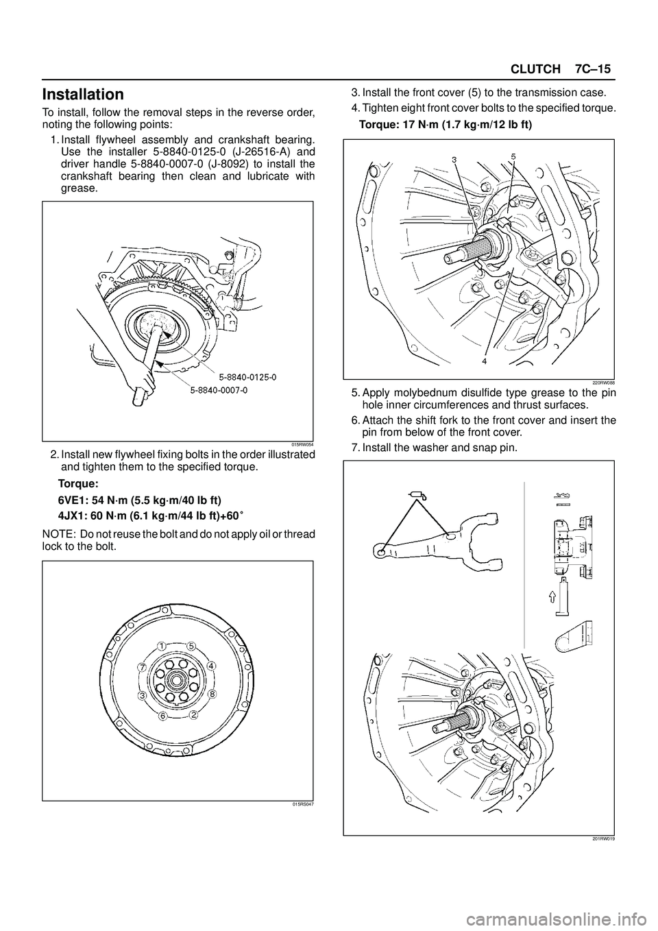
2. Install new flywheel fixing bolts in the order illustrated
and tighten them to the specified torque.
Torque:
6VE1: 54 N´m (5.5 kg´m/40 lb ft)
4JX1: 60 N´m (6.1 kg´m/44 lb ft)+60�
NOTE: Do not reuse the bolt and do not apply oil or thread
lock to the bolt.
015RS047
3. Install the front cover (5) to the transmission case.
4. Tighten eight front cover bolts to the specified torque.
Torque: 17 N´m (1.7 kg´m/12 lb ft)
220RW088
5. Apply molybednum disulfide type grease to the pin
hole inner circumferences and thrust surfaces.
6. Attach the shift fork to the front cover and insert the
pin from below of the front cover.
7. Install the washer and snap pin.
201RW019
Page 3315 of 3573
SEATS8G±3
Installation
To install, follow the removal steps in the reverse order,
noting the following points:1. Tighten the front seat assembly fixing bolts to the
specified torque.
Torque: 40 N´m (4.1 kg´m/30 lb ft)
2. Install the longest bolt to the rear inner side fixing
location, if this model is equipped with power seats.
Disassembled View (Long Wheel Base)
750RX017
Legend
(1) Head Rest
(2) Seat Back Assembly
(3) Back Board Assembly
(4) Guide Holder
(5) Trim Cover
(6) Pad & Frame Assembly
(7) Seat Heater Assembly
(8) Reclining Device
(9) Slide Cover
(10) Reclining Knob
(11) Dial (W/Height Adjuster)
(12) Frame Assembly(13) Seat Heater Assembly
(14) Pad Assembly
(15) Trim Cover
(16) Spacer (W/O Height Adjuster)
(17) Release Wire
(18) Seat Adjuster/Seat Adjuster (W/Pretensioner)
(19) Seat Belt Buckle Assembly
(20) Height Adjuster
(21) Seat Cushion Assembly
(22) Hinge Cover
(23) Pad & Frame Assembly
(24) Trim Cover
(25) Armrest Assembly
Page 3408 of 3573

EXTERIOR/INTERIOR TRIM8J±29
620RS005
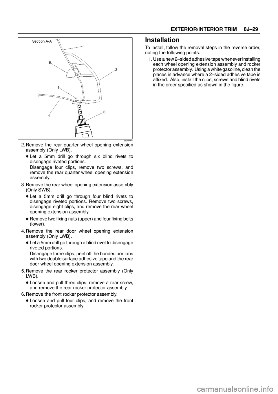
2. Remove the rear quarter wheel opening extension
assembly (Only LWB).
�Let a 5mm drill go through six blind rivets to
disengage riveted portions.
Disengage four clips, remove two screws, and
remove the rear quarter wheel opening extension
assembly.
3. Remove the rear wheel opening extension assembly
(Only SWB).
�Let a 5mm drill go through four blind rivets to
disengage riveted portions. Remove two screws,
disengage eight clips, and remove the rear wheel
opening extension assembly.
�Remove two fixing nuts (upper) and four fixing bolts
(lower).
4. Remove the rear door wheel opening extension
assembly (Only LWB).
�Let a 5mm drill go through a blind rivet to disengage
riveted portions.
Disengage three clips, peel off the bonded portions
with two double surface adhesive tape and the rear
door wheel opening extension assembly.
5. Remove the rear rocker protector assembly (Only
LWB).
�Loosen and pull three clips, remove a rear screw,
and remove the rear rocker protector assembly.
6. Remove the front rocker protector assembly.
�Loosen and pull four clips, and remove the front
rocker protector assembly.
Installation
To install, follow the removal steps in the reverse order,
noting the following points.
1. Use a new 2±sided adhesive tape whenever installing
each wheel opening extension assembly and rocker
protector assembly. Using a white gasoline, clean the
places in advance where a 2±sided adhesive tape is
affixed. Also, install the clips, screws and blind rivets
in the order specified as shown in the figure.
Page 3410 of 3573
EXTERIOR/INTERIOR TRIM8J±31
Mud Flaps (With Wheel Opening Extension)
Mud Flaps (With Wheel Opening Extension) and Associated Parts
620RW003
Legend
(1) Front Bumper Assembly
(2) Front Bumper Slider(3) Front Mud Flap
(4) Bumper Side Cover
(5) Rear Mud Flap
Removal
Front Side
1. Remove the front bumper assembly.
�Disconnect the front fog light connector and remove
two bolts from both sides of the front bumper.
2. Remove the front bumper slider(1).
�Remove two clips(4) and two nuts(3), release the
claw from the washer(2).
601RW009
3. Remove the front mud flap.
�Remove four nuts and a clip.
601RW013
Rear Side
1. Remove the bumper side cover.
2. Remove the rear mud flap.
�Remove four bolts and two nuts.
Installation
To install, follow the removal steps in the reverse order.