1998 ISUZU TROOPER bulb
[x] Cancel search: bulbPage 3191 of 3573
8E–14METER AND GAUGE
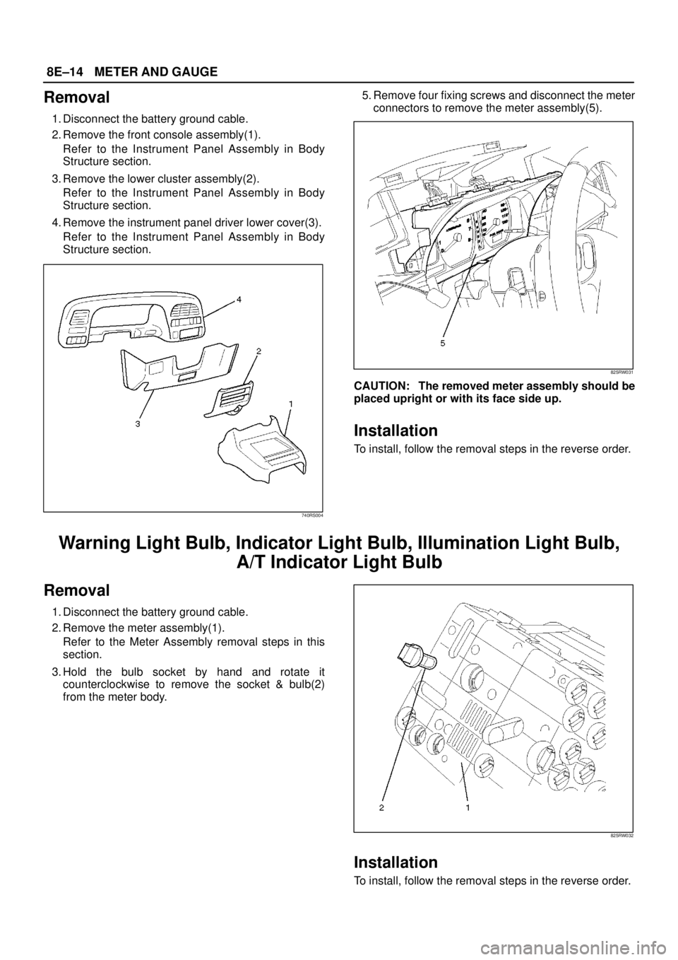
Removal
1. Disconnect the battery ground cable.
2. Remove the front console assembly(1).
Refer to the Instrument Panel Assembly in Body
Structure section.
3. Remove the lower cluster assembly(2).
Refer to the Instrument Panel Assembly in Body
Structure section.
4. Remove the instrument panel driver lower cover(3).
Refer to the Instrument Panel Assembly in Body
Structure section.
740RS004
5. Remove four fixing screws and disconnect the meter
connectors to remove the meter assembly(5).
825RW031
CAUTION: The removed meter assembly should be
placed upright or with its face side up.
Installation
To install, follow the removal steps in the reverse order.
Warning Light Bulb, Indicator Light Bulb, Illumination Light Bulb,
A/T Indicator Light Bulb
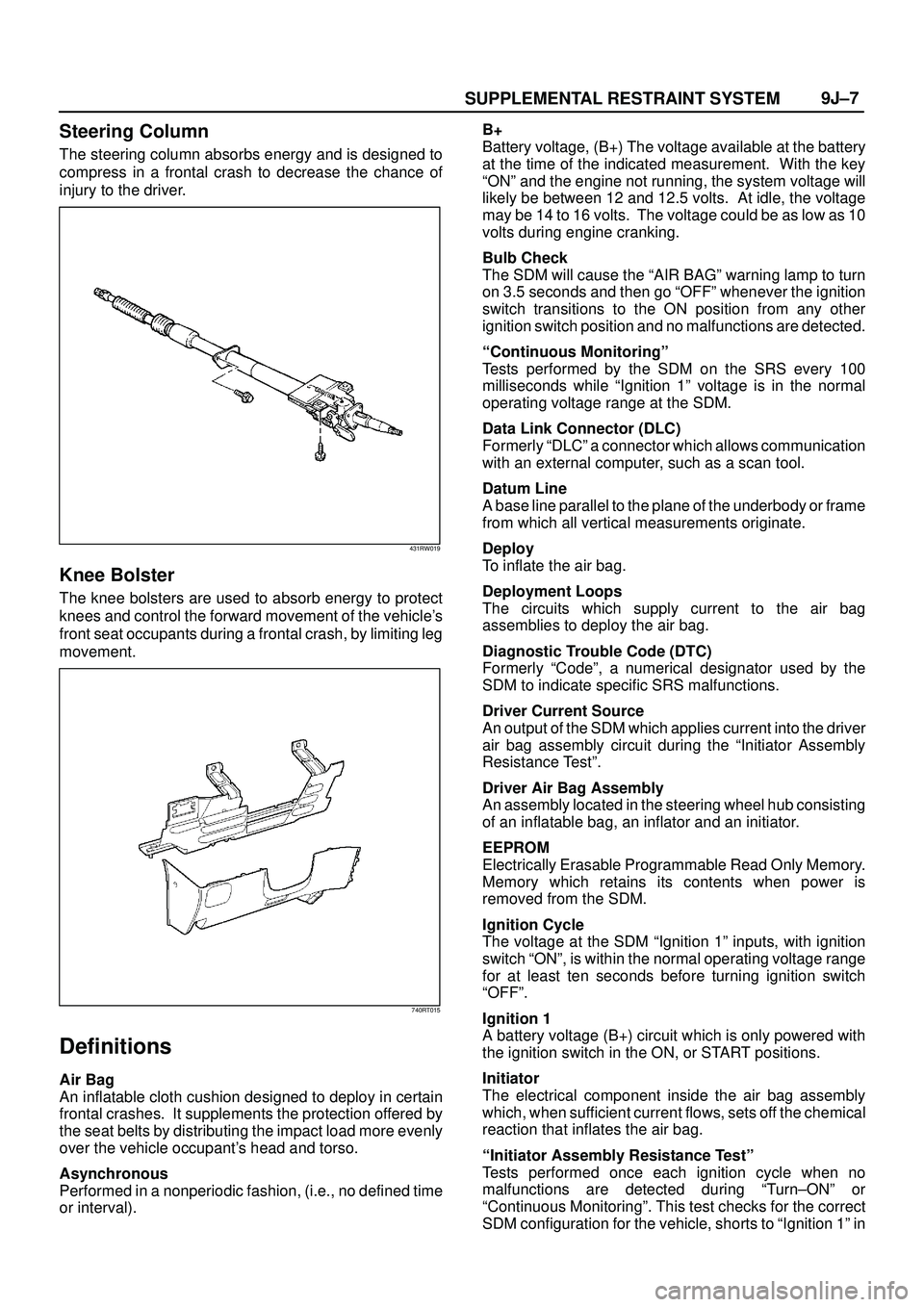
Removal
1. Disconnect the battery ground cable.
2. Remove the meter assembly(1).
Refer to the Meter Assembly removal steps in this
section.
3. Hold the bulb socket by hand and rotate it
counterclockwise to remove the socket & bulb(2)
from the meter body.
825RW032
Installation
To install, follow the removal steps in the reverse order.
Page 3444 of 3573
SUPPLEMENTAL RESTRAINT SYSTEM9J±7
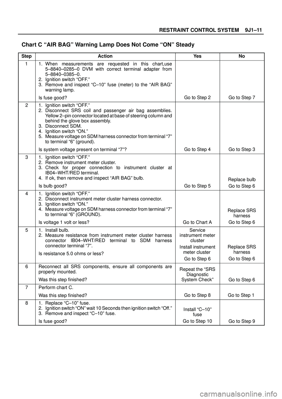
Steering Column
The steering column absorbs energy and is designed to
compress in a frontal crash to decrease the chance of
injury to the driver.
431RW019
Knee Bolster
The knee bolsters are used to absorb energy to protect
knees and control the forward movement of the vehicle's
front seat occupants during a frontal crash, by limiting leg
movement.
740RT015
Definitions
Air Bag
An inflatable cloth cushion designed to deploy in certain
frontal crashes. It supplements the protection offered by
the seat belts by distributing the impact load more evenly
over the vehicle occupant's head and torso.
Asynchronous
Performed in a nonperiodic fashion, (i.e., no defined time
or interval).B+
Battery voltage, (B+) The voltage available at the battery
at the time of the indicated measurement. With the key
ªONº and the engine not running, the system voltage will
likely be between 12 and 12.5 volts. At idle, the voltage
may be 14 to 16 volts. The voltage could be as low as 10
volts during engine cranking.
Bulb Check
The SDM will cause the ªAIR BAGº warning lamp to turn
on 3.5 seconds and then go ªOFFº whenever the ignition
switch transitions to the ON position from any other
ignition switch position and no malfunctions are detected.
ªContinuous Monitoringº
Tests performed by the SDM on the SRS every 100
milliseconds while ªIgnition 1º voltage is in the normal
operating voltage range at the SDM.
Data Link Connector (DLC)
Formerly ªDLCº a connector which allows communication
with an external computer, such as a scan tool.
Datum Line
A base line parallel to the plane of the underbody or frame
from which all vertical measurements originate.
Deploy
To inflate the air bag.
Deployment Loops
The circuits which supply current to the air bag
assemblies to deploy the air bag.
Diagnostic Trouble Code (DTC)
Formerly ªCodeº, a numerical designator used by the
SDM to indicate specific SRS malfunctions.
Driver Current Source
An output of the SDM which applies current into the driver
air bag assembly circuit during the ªInitiator Assembly
Resistance Testº.
Driver Air Bag Assembly
An assembly located in the steering wheel hub consisting
of an inflatable bag, an inflator and an initiator.
EEPROM
Electrically Erasable Programmable Read Only Memory.
Memory which retains its contents when power is
removed from the SDM.
Ignition Cycle
The voltage at the SDM ªIgnition 1º inputs, with ignition
switch ªONº, is within the normal operating voltage range
for at least ten seconds before turning ignition switch
ªOFFº.
Ignition 1
A battery voltage (B+) circuit which is only powered with
the ignition switch in the ON, or START positions.
Initiator
The electrical component inside the air bag assembly
which, when sufficient current flows, sets off the chemical
reaction that inflates the air bag.
ªInitiator Assembly Resistance Testº
Tests performed once each ignition cycle when no
malfunctions are detected during ªTurn±ONº or
ªContinuous Monitoringº. This test checks for the correct
SDM configuration for the vehicle, shorts to ªIgnition 1º in
Page 3498 of 3573
9J1±11
RESTRAINT CONTROL SYSTEM
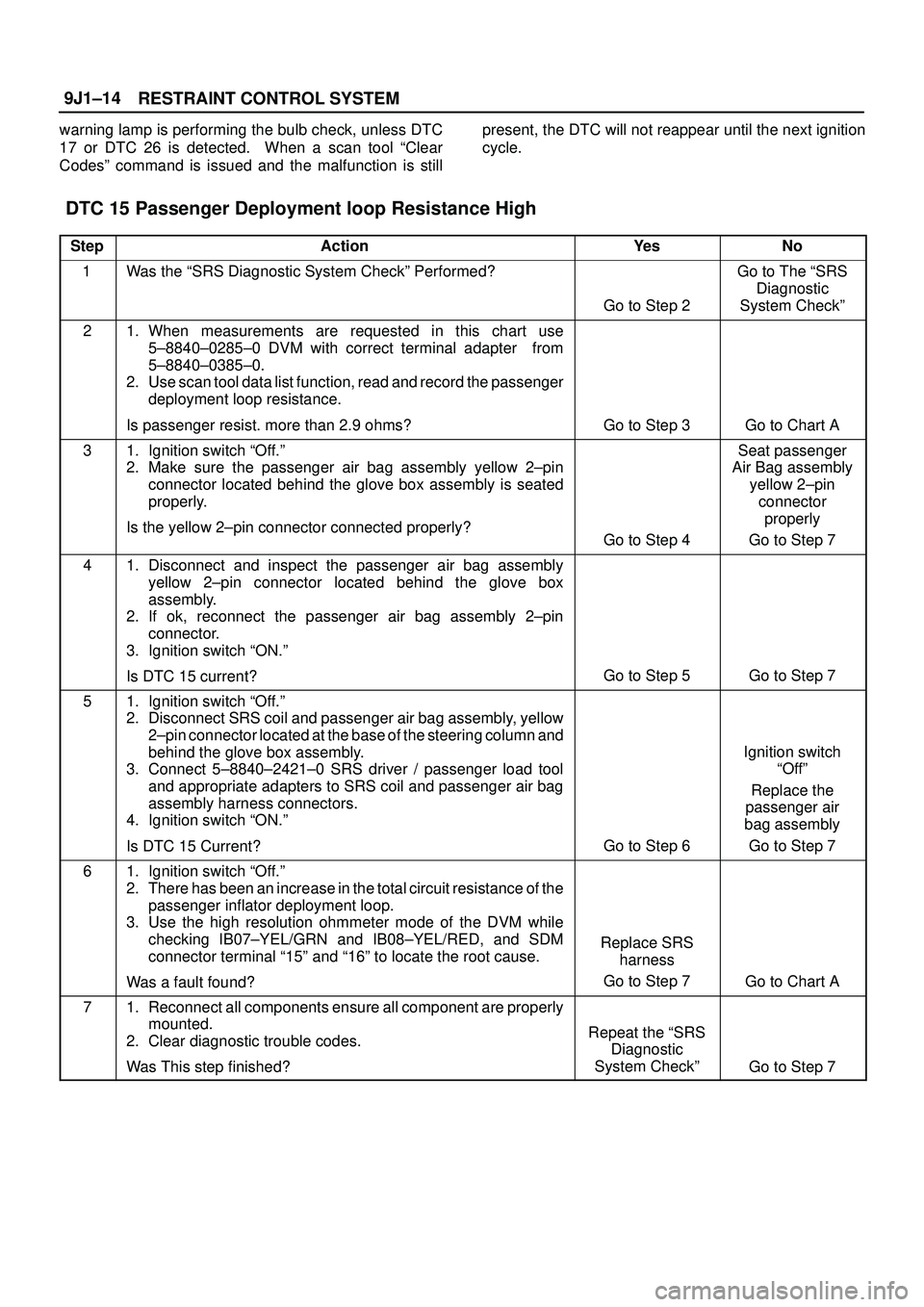
Chart C ªAIR BAGº Warning Lamp Does Not Come ªONº Steady
StepActionYe sNo
11. When measurements are requested in this chart,use
5±8840±0285±0 DVM with correct terminal adapter from
5±8840±0385±0.
2. Ignition switch ªOFF.º
3. Remove and inspect ªC±10º fuse (meter) to the ªAIR BAGº
warning lamp.
Is fuse good?
Go to Step 2Go to Step 7
21. Ignition switch ªOFF.º
2. Disconnect SRS coil and passenger air bag assemblies.
Yellow 2±pin connector located at base of steering column and
behind the glove box assembly.
3. Disconnect SDM.
4. Ignition switch ªON.º
5. Measure voltage on SDM harness connector from terminal ª7º
to terminal ª6º (ground).
Is system voltage present on terminal ª7º?
Go to Step 4Go to Step 3
31. Ignition switch ªOFF.º
2. Remove instrument meter cluster.
3. Check for proper connection to instrument cluster at
IB04±WHT/RED terminal.
4. If ok, then remove and inspect ªAIR BAGº bulb.
Is bulb good?
Go to Step 5
Replace bulb
Go to Step 6
41. Ignition switch ªOFF.º
2. Disconnect instrument meter cluster harness connector.
3. Ignition switch ªON.º
4. Measure voltage on SDM harness connector from terminal ª7º
to terminal ª6º (GROUND).
Is voltage 1 volt or less?
Go to Chart A
Replace SRS
harness
Go to Step 6
51. Install bulb.
2. Measure resistance from instrument meter cluster harness
connector IB04±WHT/RED terminal to SDM harness
connector terminal ª7º.
Is resistance 5.0 ohms or less?Service
instrument meter
cluster
Install instrument
meter cluster
Go to Step 6
Replace SRS
harness
Go to Step 6
6Reconnect all SRS components, ensure all components are
properly mounted.
Was this step finished?Repeat the ªSRS
Diagnostic
System Checkº
Go to Step 6
7Perform chart C.
Was this step finished?
Go to Step 8Go to Step 1
81. Replace ªC±10º fuse.
2. Ignition switch ªONº wait 10 Seconds then ignition switch ªOff.º
3. Remove and inspect ªC±10º fuse.
Is fuse good?
Install ªC±10º
fuse
Go to Step 10
Go to Step 9
Page 3501 of 3573
RESTRAINT CONTROL SYSTEM 9J1±14
warning lamp is performing the bulb check, unless DTC
17 or DTC 26 is detected. When a scan tool ªClear
Codesº command is issued and the malfunction is stillpresent, the DTC will not reappear until the next ignition
cycle.
DTC 15 Passenger Deployment loop Resistance High
StepActionYe sNo
1Was the ªSRS Diagnostic System Checkº Performed?
Go to Step 2
Go to The ªSRS
Diagnostic
System Checkº
21. When measurements are requested in this chart use
5±8840±0285±0 DVM with correct terminal adapter from
5±8840±0385±0.
2. Use scan tool data list function, read and record the passenger
deployment loop resistance.
Is passenger resist. more than 2.9 ohms?
Go to Step 3Go to Chart A
31. Ignition switch ªOff.º
2. Make sure the passenger air bag assembly yellow 2±pin
connector located behind the glove box assembly is seated
properly.
Is the yellow 2±pin connector connected properly?
Go to Step 4
Seat passenger
Air Bag assembly
yellow 2±pin
connector
properly
Go to Step 7
41. Disconnect and inspect the passenger air bag assembly
yellow 2±pin connector located behind the glove box
assembly.
2. If ok, reconnect the passenger air bag assembly 2±pin
connector.
3. Ignition switch ªON.º
Is DTC 15 current?
Go to Step 5Go to Step 7
51. Ignition switch ªOff.º
2. Disconnect SRS coil and passenger air bag assembly, yellow
2±pin connector located at the base of the steering column and
behind the glove box assembly.
3. Connect 5±8840±2421±0 SRS driver / passenger load tool
and appropriate adapters to SRS coil and passenger air bag
assembly harness connectors.
4. Ignition switch ªON.º
Is DTC 15 Current?
Go to Step 6
Ignition switch
ªOffº
Replace the
passenger air
bag assembly
Go to Step 7
61. Ignition switch ªOff.º
2. There has been an increase in the total circuit resistance of the
passenger inflator deployment loop.
3. Use the high resolution ohmmeter mode of the DVM while
checking IB07±YEL/GRN and IB08±YEL/RED, and SDM
connector terminal ª15º and ª16º to locate the root cause.
Was a fault found?
Replace SRS
harness
Go to Step 7
Go to Chart A
71. Reconnect all components ensure all component are properly
mounted.
2. Clear diagnostic trouble codes.
Was This step finished?
Repeat the ªSRS
Diagnostic
System Checkº
Go to Step 7
Page 3502 of 3573
9J1±15
RESTRAINT CONTROL SYSTEM
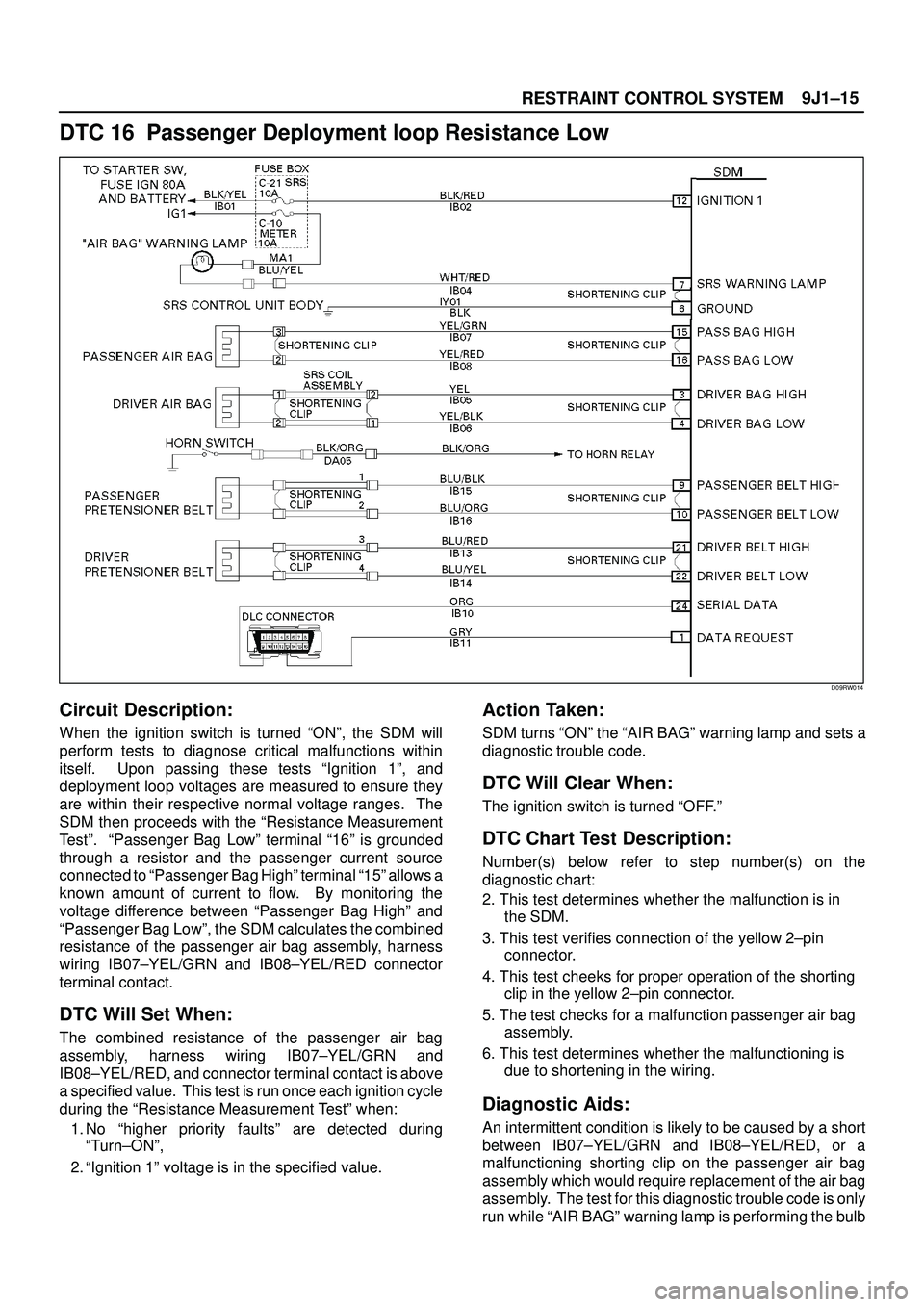
DTC 16 Passenger Deployment loop Resistance Low
D09RW014
Circuit Description:
When the ignition switch is turned ªONº, the SDM will
perform tests to diagnose critical malfunctions within
itself. Upon passing these tests ªIgnition 1º, and
deployment loop voltages are measured to ensure they
are within their respective normal voltage ranges. The
SDM then proceeds with the ªResistance Measurement
Testº. ªPassenger Bag Lowº terminal ª16º is grounded
through a resistor and the passenger current source
connected to ªPassenger Bag Highº terminal ª15º allows a
known amount of current to flow. By monitoring the
voltage difference between ªPassenger Bag Highº and
ªPassenger Bag Lowº, the SDM calculates the combined
resistance of the passenger air bag assembly, harness
wiring IB07±YEL/GRN and IB08±YEL/RED connector
terminal contact.
DTC Will Set When:
The combined resistance of the passenger air bag
assembly, harness wiring IB07±YEL/GRN and
IB08±YEL/RED, and connector terminal contact is above
a specified value. This test is run once each ignition cycle
during the ªResistance Measurement Testº when:
1. No ªhigher priority faultsº are detected during
ªTurn±ONº,
2. ªIgnition 1º voltage is in the specified value.
Action Taken:
SDM turns ªONº the ªAIR BAGº warning lamp and sets a
diagnostic trouble code.
DTC Will Clear When:
The ignition switch is turned ªOFF.º
DTC Chart Test Description:
Number(s) below refer to step number(s) on the
diagnostic chart:
2. This test determines whether the malfunction is in
the SDM.
3. This test verifies connection of the yellow 2±pin
connector.
4. This test cheeks for proper operation of the shorting
clip in the yellow 2±pin connector.
5. The test checks for a malfunction passenger air bag
assembly.
6. This test determines whether the malfunctioning is
due to shortening in the wiring.
Diagnostic Aids:
An intermittent condition is likely to be caused by a short
between IB07±YEL/GRN and IB08±YEL/RED, or a
malfunctioning shorting clip on the passenger air bag
assembly which would require replacement of the air bag
assembly. The test for this diagnostic trouble code is only
run while ªAIR BAGº warning lamp is performing the bulb
Page 3511 of 3573
RESTRAINT CONTROL SYSTEM 9J1±24
Diagnostic Aids:
An intermittent condition is likely to be caused by a poor
connection at terminals ª1º and ª2º of the SRS coil 2±pin
connector at the base of the steering column, terminal ª1º
and ª2º of the driver air bag assembly 2±pin connector at
the top of the steering column, SDM terminals ª3º and ª4º
or a poor wire to terminal connection in IB05±YEL orIB06±YEL/BLK. The test for this diagnostic trouble code
is only run while the ªAIR BAGº warning lamp is
performing the bulb check, unless DTC 17 or DTC 26 is
detected. When a scan tool ªClear Codesº command is
issued and the malfunction is still present, the DTC will not
reappear until the next ignition cycle.
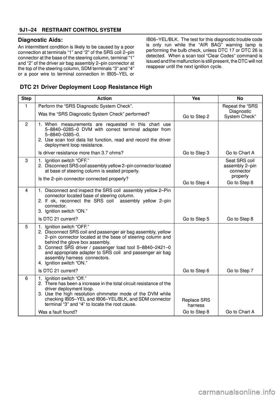
DTC 21 Driver Deployment Loop Resistance High
StepActionYe sNo
1Perform the ªSRS Diagnostic System Checkº.
Was the ªSRS Diagnostic System Checkº performed?
Go to Step 2
Repeat the ªSRS
Diagnostic
System Checkº
21. When measurements are requested in this chart use
5±8840±0285±0 DVM with correct terminal adapter from
5±8840±0385±0.
2. Use scan tool data list function, read and record the driver
deployment loop resistance.
Is driver resistance more than 3.7 ohms?
Go to Step 3Go to Chart A
31. Ignition switch ªOFF.º
2. Disconnect SRS coil assembly yellow 2±pin connector located
at base of steering column is seated properly.
Is the 2±pin connector connected properly?
Go to Step 4
Seat SRS coil
assembly 2±pin
connector
properly
Go to Step 8
41. Disconnect and inspect the SRS coil assembly yellow 2±Pin
connector located base of steering column.
2. If ok, reconnect the SRS coil assembly yellow 2±pin
connector.
3. Ignition switch ªON.º
Is DTC 21 current?
Go to Step 5Go to Step 8
51. Ignition switch ªOFF.º
2. Disconnect SRS coil and passenger air bag assembly, yellow
2±pin connector located at the base of steering column and
behind the glove box assembly.
3. Connect SRS driver / passenger load tool 5±8840±2421±0
and appropriate adapter to SRS coil and passenger air bag
assembly harness connectors.
4. Ignition switch ªON.º
Is DTC 21 current?
Go to Step 6Go to Step 7
61. Ignition switch ªOff.º
2. There has been a increase in the total circuit resistance of the
driver deployment loop.
3. Use the high resolution ohmmeter mode of the DVM while
checking IB05±YEL and IB06±YEL/BLK, and SDM connector
terminal ª3º and ª4º to locate the root cause.
Was a fault found?
Replace SRS
harness
Go to Step 8
Go to Chart A
Page 3514 of 3573
9J1±27
RESTRAINT CONTROL SYSTEM
malfunctioning shorting clip on the driver air bag
assembly or SRS coil assembly which would require
replacement of the component. The test for this
diagnostic trouble code is only run while the ªAIR BAGº
warning lamp is performing the bulb check, unless DTC17 or DTC 26 is detected. When a scan tool ªClear
Codesº command is issued and the malfunction is still
present, the DTC will not reappear until the next ignition
cycle.
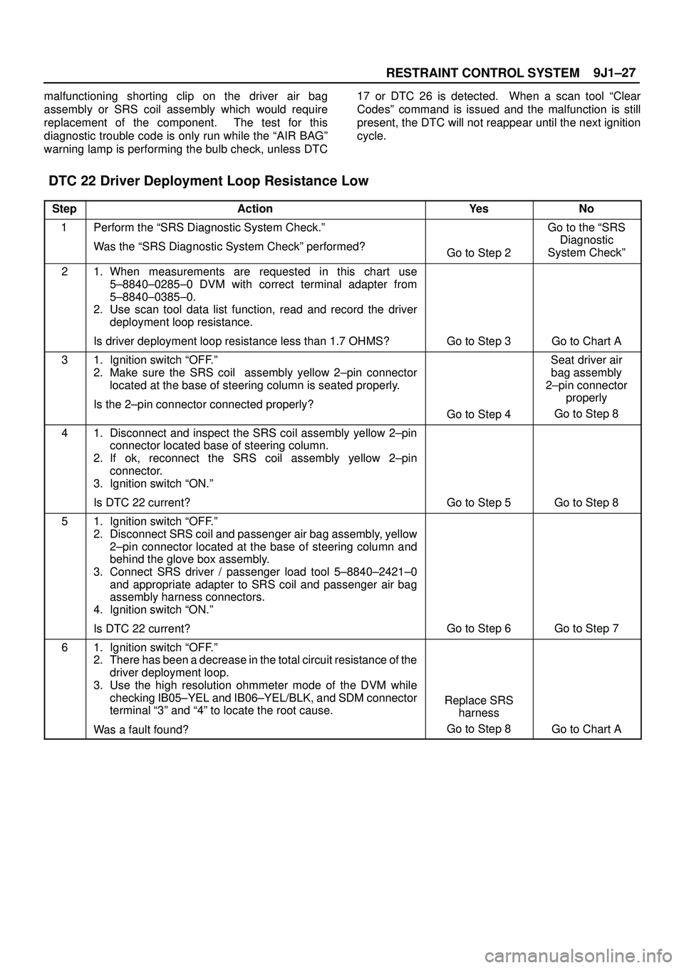
DTC 22 Driver Deployment Loop Resistance Low
StepActionYe sNo
1Perform the ªSRS Diagnostic System Check.º
Was the ªSRS Diagnostic System Checkº performed?
Go to Step 2
Go to the ªSRS
Diagnostic
System Checkº
21. When measurements are requested in this chart use
5±8840±0285±0 DVM with correct terminal adapter from
5±8840±0385±0.
2. Use scan tool data list function, read and record the driver
deployment loop resistance.
Is driver deployment loop resistance less than 1.7 OHMS?
Go to Step 3Go to Chart A
31. Ignition switch ªOFF.º
2. Make sure the SRS coil assembly yellow 2±pin connector
located at the base of steering column is seated properly.
Is the 2±pin connector connected properly?
Go to Step 4
Seat driver air
bag assembly
2±pin connector
properly
Go to Step 8
41. Disconnect and inspect the SRS coil assembly yellow 2±pin
connector located base of steering column.
2. If ok, reconnect the SRS coil assembly yellow 2±pin
connector.
3. Ignition switch ªON.º
Is DTC 22 current?
Go to Step 5Go to Step 8
51. Ignition switch ªOFF.º
2. Disconnect SRS coil and passenger air bag assembly, yellow
2±pin connector located at the base of steering column and
behind the glove box assembly.
3. Connect SRS driver / passenger load tool 5±8840±2421±0
and appropriate adapter to SRS coil and passenger air bag
assembly harness connectors.
4. Ignition switch ªON.º
Is DTC 22 current?
Go to Step 6Go to Step 7
61. Ignition switch ªOFF.º
2. There has been a decrease in the total circuit resistance of the
driver deployment loop.
3. Use the high resolution ohmmeter mode of the DVM while
checking IB05±YEL and IB06±YEL/BLK, and SDM connector
terminal ª3º and ª4º to locate the root cause.
Was a fault found?
Replace SRS
harness
Go to Step 8
Go to Chart A
Page 3533 of 3573
RESTRAINT CONTROL SYSTEM 9J1±46
warning lamp is performing the bulb check. When a scan
tool ªClear Codesº command is issued and themalfunction is still present, the DTC will not reappear until
the next ignition cycle.
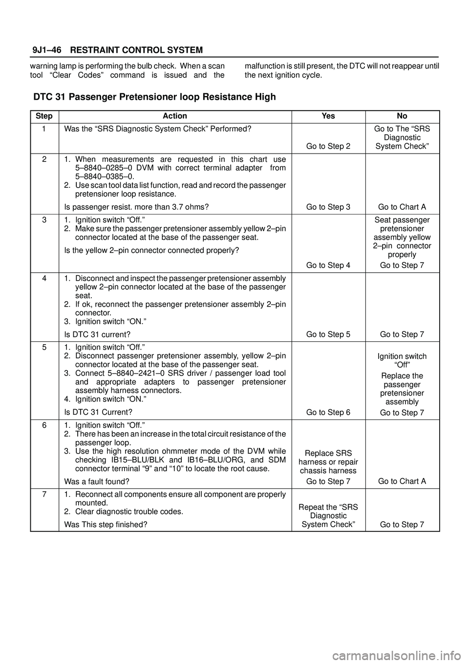
DTC 31 Passenger Pretensioner loop Resistance High
StepActionYe sNo
1Was the ªSRS Diagnostic System Checkº Performed?
Go to Step 2
Go to The ªSRS
Diagnostic
System Checkº
21. When measurements are requested in this chart use
5±8840±0285±0 DVM with correct terminal adapter from
5±8840±0385±0.
2. Use scan tool data list function, read and record the passenger
pretensioner loop resistance.
Is passenger resist. more than 3.7 ohms?
Go to Step 3Go to Chart A
31. Ignition switch ªOff.º
2. Make sure the passenger pretensioner assembly yellow 2±pin
connector located at the base of the passenger seat.
Is the yellow 2±pin connector connected properly?
Go to Step 4
Seat passenger
pretensioner
assembly yellow
2±pin connector
properly
Go to Step 7
41. Disconnect and inspect the passenger pretensioner assembly
yellow 2±pin connector located at the base of the passenger
seat.
2. If ok, reconnect the passenger pretensioner assembly 2±pin
connector.
3. Ignition switch ªON.º
Is DTC 31 current?
Go to Step 5Go to Step 7
51. Ignition switch ªOff.º
2. Disconnect passenger pretensioner assembly, yellow 2±pin
connector located at the base of the passenger seat.
3. Connect 5±8840±2421±0 SRS driver / passenger load tool
and appropriate adapters to passenger pretensioner
assembly harness connectors.
4. Ignition switch ªON.º
Is DTC 31 Current?
Go to Step 6
Ignition switch
ªOffº
Replace the
passenger
pretensioner
assembly
Go to Step 7
61. Ignition switch ªOff.º
2. There has been an increase in the total circuit resistance of the
passenger loop.
3. Use the high resolution ohmmeter mode of the DVM while
checking IB15±BLU/BLK and IB16±BLU/ORG, and SDM
connector terminal ª9º and ª10º to locate the root cause.
Was a fault found?
Replace SRS
harness or repair
chassis harness
Go to Step 7
Go to Chart A
71. Reconnect all components ensure all component are properly
mounted.
2. Clear diagnostic trouble codes.
Was This step finished?
Repeat the ªSRS
Diagnostic
System Checkº
Go to Step 7