Page 1145 of 1681
lgnition System
23-88
Component Location lndex
rGNlTroN TTMTNG COJTRqL SYSTEM
. lnspection and sefting, page 23-90
DISTRIBUTORTop End lnspeclion, page 23-92Removal/lnstallation, pages 23-92, 93Overhaul, page 23 94Reassembly, page 23-95lgnition Coil TesvReplacement, page 23 96lgnition Control Module (lCM) lnput Test, page 23-97
PLUGSInspection, pago 23-98
IGN'TION WIRESInspection, page 23-95
SERVICE CHECK CONNECTOR I2PIIWi]6 coloEi BRN/WHT I
land BLK j
Page 1154 of 1681
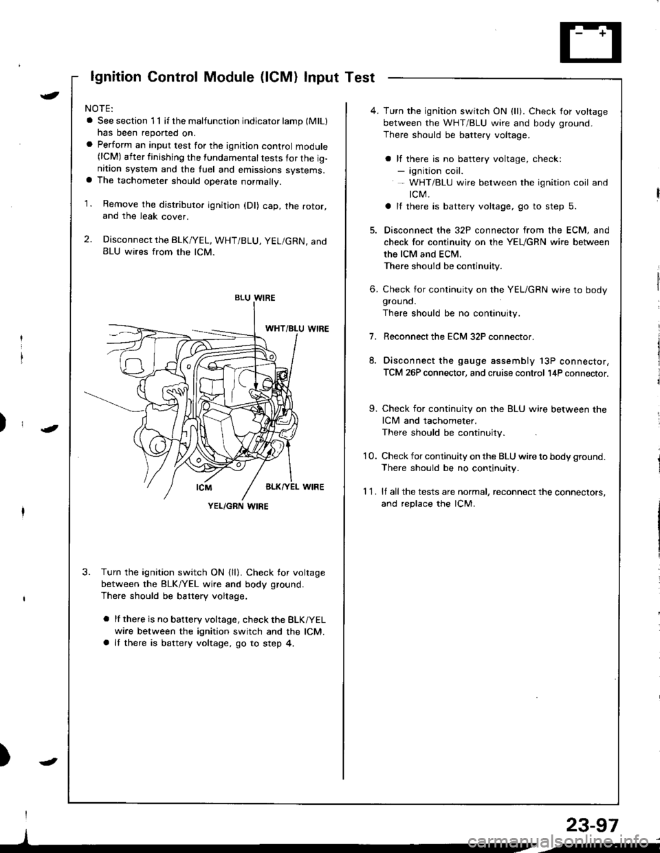
lgnition Control Module (lCM) Input Test
NOTE:
a See section 1 1 if the malfunction indicator lamp (MlLl
has been reported on.a Perform an input test for the ignition control module(lCM) after finishing the fundamental tests for the ig-nition system and the fuel and emissions systems.a The tachometer should operate normally.
1. Remove the distributo. ignition (Dl) cap, the rotor,and the leak cover.
2. Disconnect the BLK/YEL, WHT/BLU, YEL/GRN, andBLU wires from the lCM.
3. Turn the ignition switch ON {ll}. Check for voltage
between the BLK/YEL wire and body ground.
There should be battery voltage.
a lf there is no battery voltage, check the BLKiYEL
wire between the ignition switch and the lCM.a It there is battery voltage, go to step 4,
)
I
)
BLU WIRE
YEL/GRN I,\'IRE
4. Turn the ignition switch ON (ll). Check for voltage
between the WHT/BLU wire and body ground.
There should be battery voltage.
a lf there is no battery voltage, check:- ignition coil.- WHT/BLU wire between the ignition coil and
tcM.
a lf there is battery voltage, go to step 5.
5. Disconnect the 32P connector from the ECM, and
check for continuity on the YEUGRN wire between
the ICM and ECM.
There should be continuity.
6. Check for continuity on the YEL/GRN wire to bodygrouno.
There should be no continuity.
7.Reconnect the ECM 32P connector.
Disconnect the gauge assembly 13P connector,
TCM 26P connector, and cruise control l4P connector.
9. Check for continuity on the BLU wire between the
ICM and tachometer.
There should be continuity.
'10. Check for continuity on the BLU wire to body ground.
There should be no continuity.
1 1 . lf all the tests are normal, reconnect the connectors,
and replace the lCM.
23-97
/i
Page 1167 of 1681
Charging System
Rotor Slip Ring Test
DENSO:'l . Check that there is continuity between the slip rings.
ROTOR SHAFT
Check that there is no continuity between the slip
rings and the rotor or rotor shaft.
lf the rotor fails either continuity check, replace the
alternator.
Stator Test
1 . Check that there is continuity between each pair ot
leads.
Check that there is no continuity between each lead
and the coil core.
lf the coil lails either continuity check, replace the
alternator.
2.
3.
2.
3.
23-110
cotl coRE
b-.
Page 1170 of 1681
i'[
Rotor Slip Ring TestAlternator Brush Inspection
Separate the drive-end housing from the rear hous-
ing as described on page 23-l 1 1.
Separate the rear housing from the stator/rectifier
assembly by removing the four screws and the ter-
minal nut from the rear housing (see page 23-111).
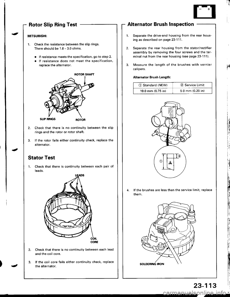
Measure the length of the brushes with vernier
calrpers.
Alternator Brush Length:
O Standard (NEW)O Service Limit
19.0 mm (0.75 in)5.0 mm (0.20 in)
lf the brushes are less than the service limit, replace
them.
23-113
{
J
lFr
MITSUBISHI:
1. Checkthe resistance between the slip rings.
There should be 1.8 - 3.0 ohms.
. lf resistance meets the specification, go to step 2,
. lf resistance does not meet the specification,
replace the alternator.
SLIP RII{GS
Check that there is no continuity between the slip
rings and the rotor or rotor shaft.
lf the rotor fails either continuity check, replace the
alternator.
Stator Test
1. Check that there is continuity between each pair of
leads.
co|LconE
Check that there is no continuity between each
and the coil core.
lf the coil core fails either continuity check, replace
the alternator.
ROIOR SHAFT
J
"-
Page 1187 of 1681
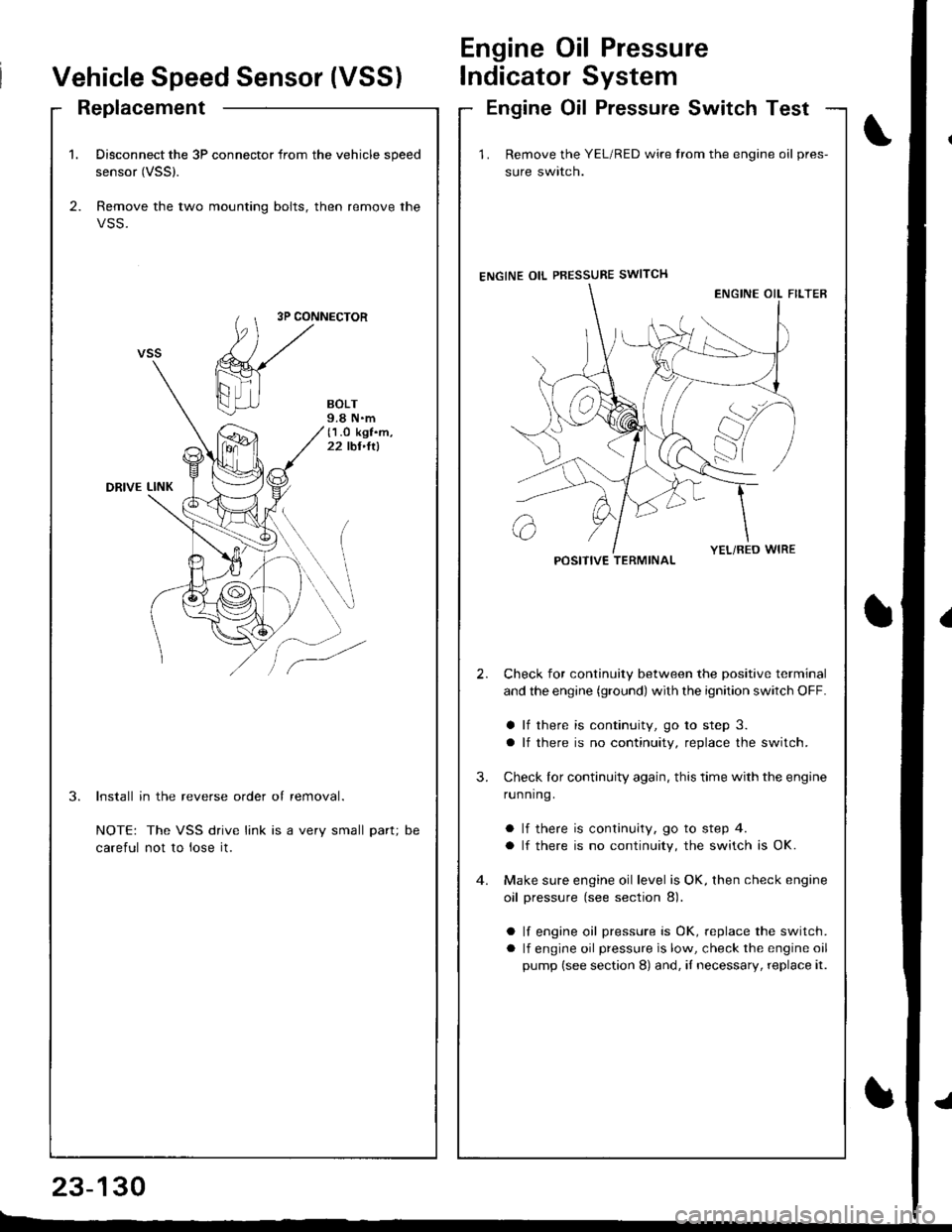
1. Disconnect the 3P connector from the vehicle speed
sensor (VSSl.
2. Remove the two mounting bolts, then remove the
VSS.
3P CONNECTOR
BOLT9.8 N.m(1.O kgf.m,22 tbt,ltl
DRIVE LINK
3.Install in the reverse order of removal.
NOTE: The VSS drive link is a very small part;
careful not to lose it.
DC
Vehicle Speed Sensor (VSS)
Engine Oil Pressure
lndicator System
ReplacementEngine Oil Pressure Switch Test
23-130
E-_
1 . Remove the YEL/RED wire trom the engine oil pres-
sure swlrcn.
ENGINE OIL PBESSURE SWITCH
Check for continuity between the positive terminal
and the engine (ground) with the ignition switch OFF.
a lf there is continuity, go to step 3.
a lf there is no continuity, replace the switch.
Check lor continuity again, this time with the engine
running.
a lf there is continuity, go to step 4.
a lf there is no continuity, the switch is OK.
Make sure engine oil level is OK, then check engine
oil pressure (see section 8).
a lf engine oil pressure is OK, replace the switch.
a lf engine oil pressure is low, check the engine oil
pump (see section 8) and, iI necessary, replace it.
2.
3.
POSITIVE TERMINAL
Page 1188 of 1681
)
{
t.t
t.!
23-131
Fuel Gauge
Gauge Test
NOTE: Refer to page 23-123 for the fuel gauge system
circuit.
1. Check the No. 25 (7.5 A) fuse in the under-dash
fuse/relay box before testing.
2. Remove the rear seat (see section 20).
Remove the protective cover and access panel from
the tloor.
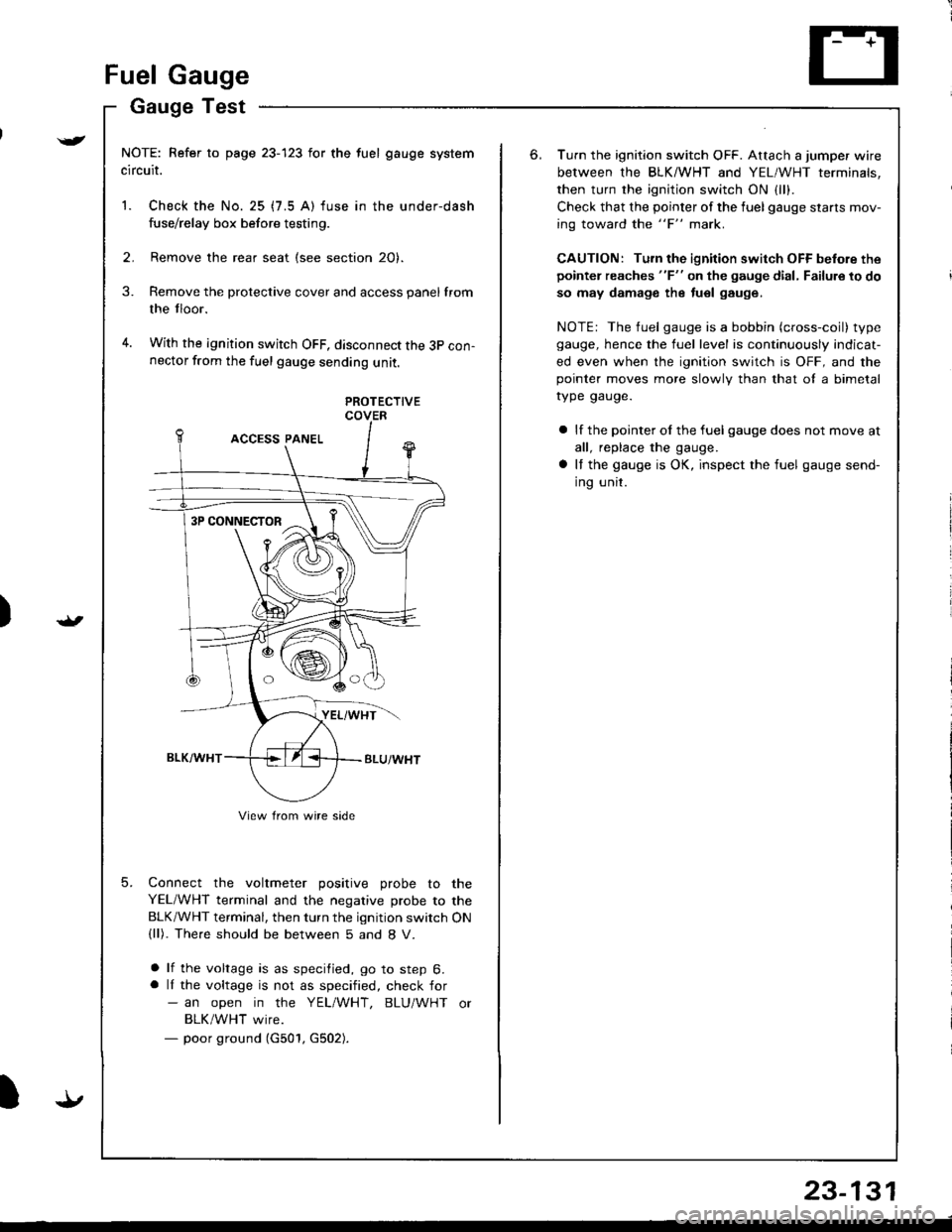
With the ignition switch OFF, disconnect the 3p con-nector from the fuel gauge sending unit.
3.
4.
5.
PROTECTIVECOVER
Connect the voltmeter positive probe to the
YEL/WHT terminal and the negative probe to the
BLK/WHT terminal, then turn the ignition switch ON(ll). The.e should be between 5 and 8 V.
a lf the voltage is as specified, go to step 6.a lI the voltage is not as specified, check for- an open in the YEL/WHT, BLU/WHT or
BLK/WHT wire.- poor ground (G501, G502).
3P CONNECTOR
View from wire side
6.Turn the ignition switch OFF. Attach a jumper wire
between the BLKMHT and YEL/WHT terminals,
then turn the ignition switch ON {1.,.
Check that the pointer of the fuel gauge starls mov-
ing toward the "F" mark.
CAUTION: Turn the ignition switch OFF before the
pointer reaches "F" on the gauge dial, Failure to do
so may damage the tuel gauge.
NOTE: The fuel gauge is a bobbin (cross-coil) type
gauge, hence the fuel level is continuously indicat-
ed even when the ignition switch is OFF, and thepointer moves more slowlv than that ol a bimetal
rype gauge.
a lf the pointer ol the fuel gauge does not move at
all, replace the gauge.
a It the gauge is OK, inspect the fuel gauge send-
ing unit.
Page 1209 of 1681
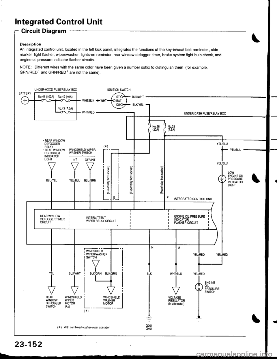
Integrated Control Unit
Circuit Diagram
Description
An integrated control unit, located in lhe left kick panel, integrates the lunctions of the key-in/seat belt r€minder , side
marker light llasher, wiper/washer, lights-on reminder, rear window delogger timer, brake system light bulb check, and
engine oil pressure indicator flasher circuits.
NOTE: Different wires with the same color have been given a nu mber suflix to distinguish them (for example,
GRN/RED I and GRN/RED'� are not the same).
REAR WINDOWDEFOGGERRELAYREAF WINDOWDEFOGGENIND CATORL GHT
f-7
IIBLU/YEL
WHT/ BLK
WHT/ REO
+WHT
WNDSHIELDWIPERiWASHER SWITCH
INT OFF/INT
f7 f7
tltlYEUBLU 8LU/GRN
BLUMHT
J
wtN0sHr€10WIPERMOTOR
UNDER.DASH FUSARETAY BOX
F rmecnlleo counoL ultr
YEUBLU
rYEUBLU
YEUREO YEUREO
tl
IYEURED
LOWENGINEOIIPRESSUREINOICATOBLIGHT
; WINDSHIELD' WIPERMASHERI swlTcH
tf7IVtlYEL
J
FEARwtN00wOEFOGGERSWITCH
WHTIBLU
J
VOTTAGEREGULATOR(ln allernatol)
BLK
G441
ENGINEolLPRESSUREswrTcH
UNDER-NOOO FUSE/RELAY BOX
1.6
:6
t;t-L
i
"'i'- 'i*-
|
I Il
I vi: WINDSHIELO II WASHEB I
L__ "oto: _ __l(*)
n
s
s
,]
23-152
(*) :Wilh combined washer-wiper operalion
Page 1213 of 1681
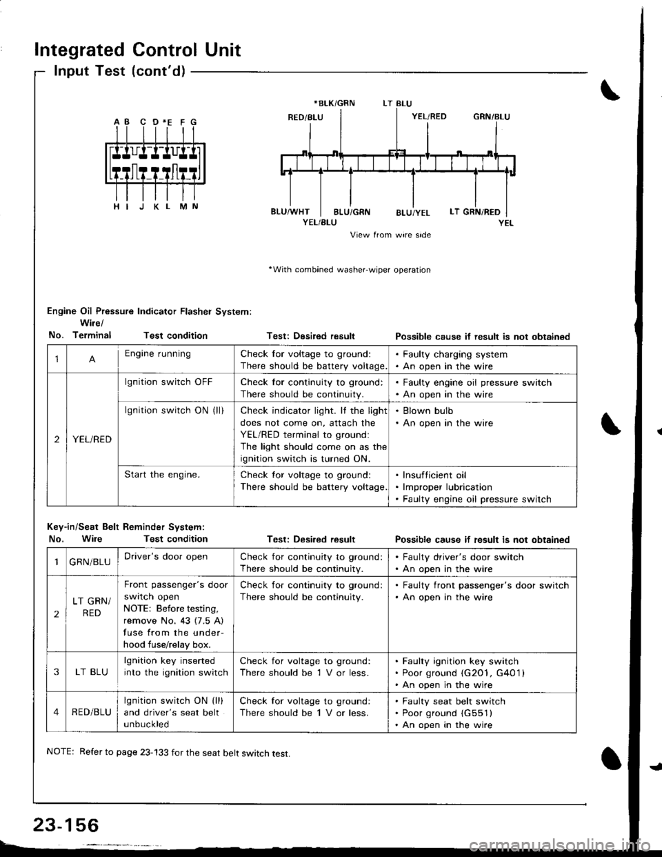
Integrated Control Unit
lnput Test (cont'd)
YEL/BLU
View from wire side
'With combined washer-wiper operation
Engine Oil Pressure Indicator Flasher System:
Wire/
No. TerminalTest condition
Key-in/Seat Belt Reminder System:
No. WileTest condition
Testi Desired result
Test: Desired result
Possible cause if result is not obtainsd
Possible cause if fesult is not obtained
*BLK/GRN
1Engine runningCheck for voltage to ground:
There should be battery voltage.
. Faulty charging system. An open in the wire
2YEL/RED
lgnition switch OFFCheck for continuity to ground:
There should be continuity.
. Faulty engine oil pressure switch. An open in the wire
lgnition switch ON (ll)Check indicator light. It the light
does not come on, attach the
YEL/RED terminal to groundl
The light should come on as the
ignition switch is turned ON.
. Blown bulb. An open in the wire
Start the engine.Check tor voltage to ground:
There should be battery voltage
lnsufticient oil
lmproper lubrication
Faulty engine oil pressure switch
1GRN/BLUDriver's door openCheck for continuity to ground:
There should be continuity.
. Faulty driver's door switch. An open in the wire
2
LT GRN/
RED
Front passenger's door
swrlcn open
NOTE: Before testing,
remove No. 43 {7.5 A)
fuse from the under-
hood fuse/relay box.
Check for continuity to ground:
There should be continuity.
. Faulty front passenger's door switch'An open in the wire
3LT BLU
lgnition key inserted
into the ignition switch
Check for voltage to ground:
There should be 1 V or less.
Faulty ignition key switch
Poor ground (G2O1, G401 l
An open in the wire
4RED/BLU
lgnition switch ON (lll
and driver's seat belt
unbuckled
Check for voltage to ground:
There should be 1 V or less.
Faulty seat belt switch
Poor ground (G551l
An open in the wire
NOTE: Refer to page 23-133 for the seat belt switch test.