1998 HONDA INTEGRA check oil
[x] Cancel search: check oilPage 1032 of 1681
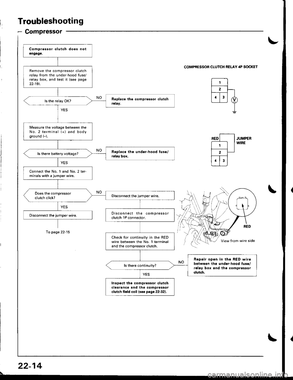
Troubleshooting
- Compressor
Remove the compressor clutchrelay trom the unde.hood tuse/relay box, and test it {see page
22-19t.
Measure the voltage beNveen theNo.2 terminal (+) and bodyground (-).
ls there battery voltage?
Connect the No. 1 and No. 2 terminals with a jumper wire.
Discon nect the compressorclutch 1P conoector.
Check lor continuity in the REDwire betlveen the No. 1 terminaland the compressor clutch.
Reprir open in tha BED wirabotwoon th6 undar-hood fusc/rolay box and lhs comp.osrorclutch.
In3p6ct th€ compre3sor clulchclear'nc€ and the comDressorcfutch ti€fd coil (se€ ptge22-321.
\-
COMPRESSOR CLUICH RELAY 'P SOCKET
JUMPERWIRE
\
To page 22-15
22-14
\
Page 1041 of 1681
J
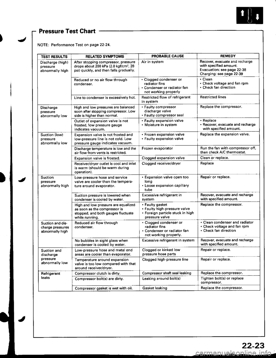
Pressure Test Chart
Performance Test on page 22.24.
TEST RESULTSRELATED SYMPTOMSPROBABLE CAUSEREMEDY
Discharge (highlpressure
abnormally high
After stopping compressor, pressure
drops about 200 kPa (2.0 kgflcm'�,28psi) quickly, and then falls gradually.
Air in systemRecover, evacuate and rechargewith specified amount.Evacuation: see pag€ 22-38Charging: see page 22-39
Reduced or no air tlow throughconoenser.
. Clogged condenser orradiator fins. Condenser or radialor fannot working proPerly
CleanCheck voltage and fan rpmCheck fan direction
Line lo condenser is excessively hot.Restricted flow of felrigerantin systemRestricted lines
Dischargepressureabnormally low
High and low pressures are balancedsoon after stopping compressor. Lowside is higherthan normal.
. Faulty compressordischarge valve. Faulty compressor seal
Replace the compressor.
Outlet of expansion valve is notfrosted, low pressure gauge
indicates vacuum.
. Faulty expansion valve. lvloisture in system
. Replace. Recover, evacuate and rechargewith specified amount.
Suction (low)pressure
abnormally low
Expansion valve is not frosted andlow-pressure line is not cold. Lowpressure gauge indicates vacuum.
Frozen expansion valveFaulty expansion valveReplace the expansion valve.
Discharge temperature is low and theairflow from vents is restricted.Frozen evaporatorRun the fan with compressor off,then check A,/C thermostat.
Expansion valve is frosted.Clogged expansion valveClean or replace.
Receiver/dryer outlet is cool and inletis warm (should be warm duringoperal|onJ.
Clogged receiver/dryerReplace
Suctionpressureabnormally high
Low-pressure hose and seryicevalve are cooler than the temPera-ture around evaporator.
Expansion valve open toolongLoose expansion capillarytube
Repair or replace.
Suction pressure is lowered whencondenser is cooled by water.Excessive refrigerant insystemRecover. evacuate and rechargewith specified amount.
High and low pressure are equalizedas soon asthe compressor asstopped, and both gauges fluctuatewhile running.
Faulty gasket
Faulty high-pressure valveForeign panicle stuck in highpressure valve
Reolace the comDressor.
Suction and dis-charge pr€ssuresabnormally high
Reduced air flow throughcondenser.
. Clogged condenser orradiator fins. Condenser or radiator lannot working properly.
Clean condenser and radiatorCheck voltage and fan rpmCheck fan direction
No bubbles in sight glass whencondenser is cooled bv water.Excessive refrigerant in systemRecover. evacuate and rechargewith specified amount.
Suction anddischargepfessure
abnormally low
Low-pressure hose and metal endareas are cooler than evaDorator.Clogged or kinked lowpressure hose partsRepair or replace.
TemP€rature around expansionvalve is too low compared with thataround receiv€r/dryer.
Clogged high-pressure lineRepair or replace.
RetrigerantleaksCompressor clutch is dirty.Compressor shaft seal leakingReplace the compressor.
Comoressor bolt(s) are dirty.Leaking around bolt(s)Tighten bolt{s) or replacecompressor.
Compressor gasket is wet with oil.Gasket leakingReolace the comoressor.
22-23
Page 1050 of 1681
Compressor
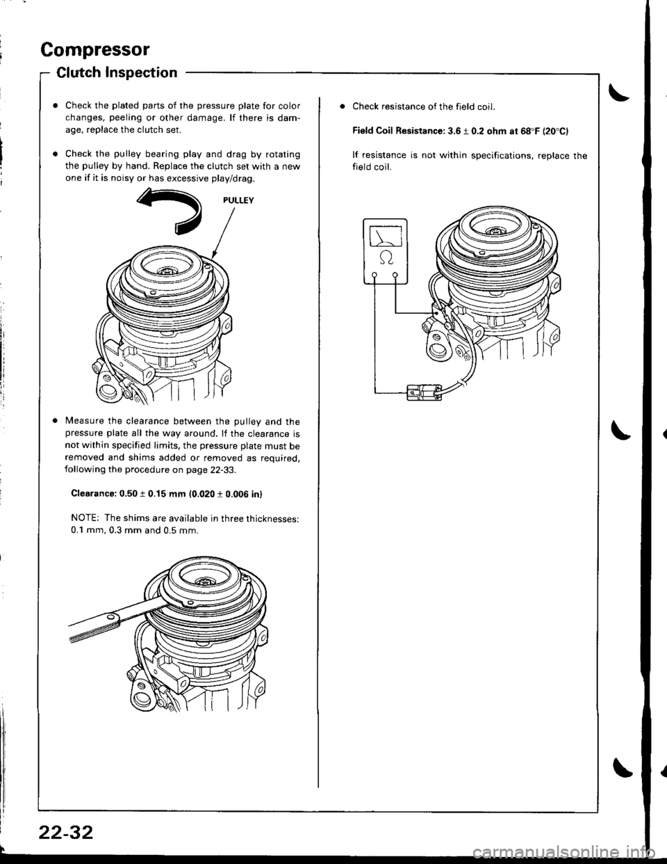
Clutch Inspection
Check the plated parts of the pressure plate for color
changes, peeling or other damage. lf there is dam-
age, replace the clutch set.
Check the pulley bearing play and drag by rotating
the pulley by hand. Replace the clutch set with a new
one if it is noisy or has excessive play/drag.
Measure the clearance between the Dullev and thepressure plate all the way around. lf the clearance is
not within specified limits, the pressure plate must beremoved and shims added or removed as required,following the procedure on page 22-33.
Clearanca: 0.50 t 0.15 mm (0.020 r 0.006 in)
NOTE; The shims are available in three thicknesses:
0.1 mm, 0.3 mm and 0.5 mm.
22-32
Check resistance of the field coil.
Field Coil Resistance: 3.6 1 0.2 ohm at 68'F {20'C)
lf resistance is not within specifications, replace the
field coil.
Page 1052 of 1681
Compressor
a
a
Clutch Overhaul (cont'dl
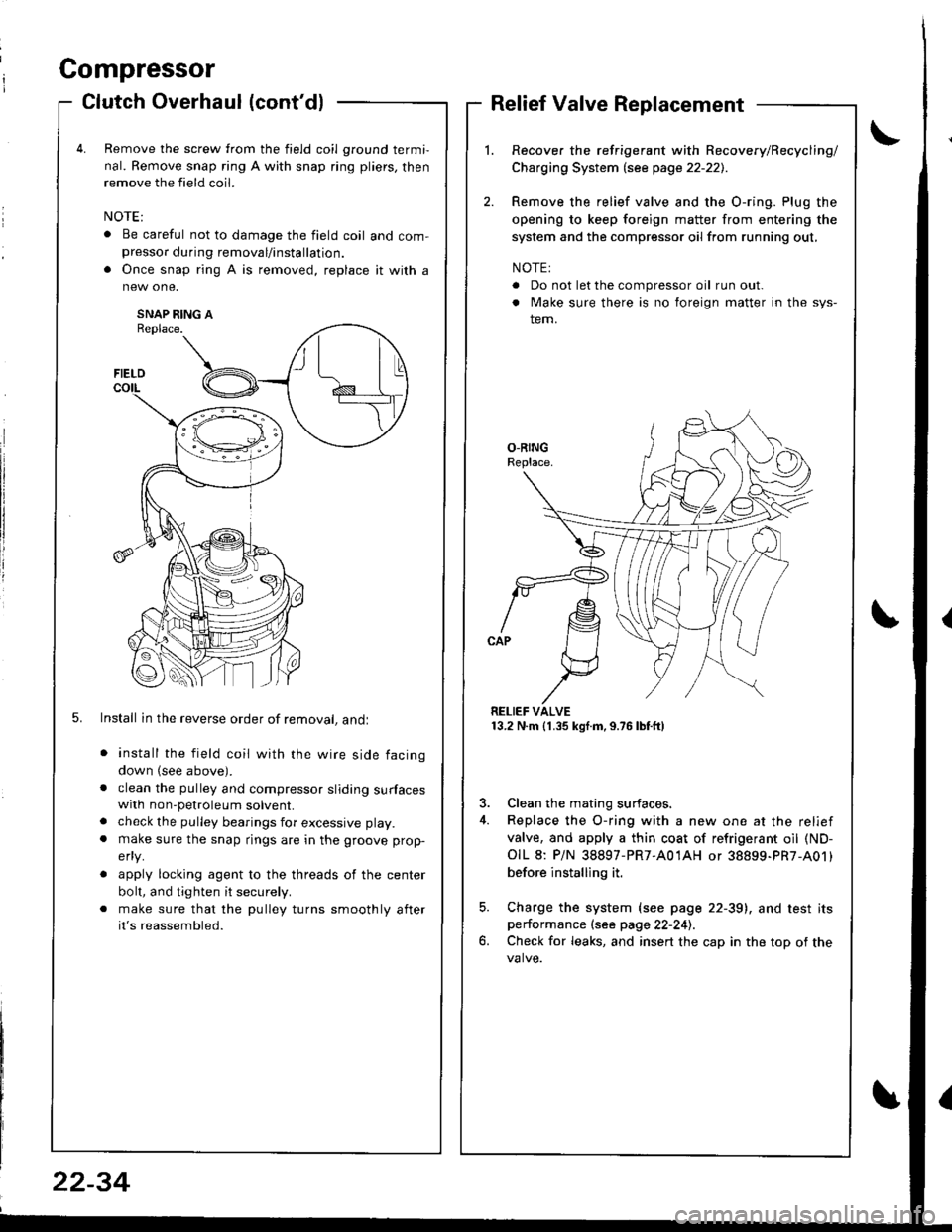
Remove the screw from the field coil ground termi,
nal. Remove snap ring A with snap ring pliers, then
remove the field coil.
. Be careful not to damage the field coil and com-presso. during removal/installation.
. Once snap ring A is removed, replace it with a
SNAP RING AReplace.
5. Install in the reverse order of removal, andl
install the field coil with the wire side facing
down (see above).
clean the pulley and compressor sliding surfaceswith non-petroleum solvent.
check the pulley bearings for excessive play.
make sure the snap rings are in the groove prop-
efly.
apply locking agent to the threads of the center
bolt, and tighten it securely.
make sure that the pulley turns smoothly after
it's reassembled.
Relief Valve Replacement
Recover the refrigerant with Recovery/Recycling/
Charging System lsee page 22-221.
Remove the relief valve and the O-ring. Plug the
opening to keep foreign matter from entering the
system and the compressor oil from running out,
NOTE:
. Do not let the compressor oil run out.
. Make sure there is no foreign matter in the sys-
tem.
RELIEF VALVE13.2 N.m (1.35 kgf.m,9.76lbtft)
3. Clean the mating surfaces.
4. Replace the O-ring with a new one at the relief
valve, and apply a thin coat of refrigerant oil (ND-
OIL 8: P/N 38897-PR7-A01AH or 38899-PR7-A01)
before installing it.
5. Charge the system (see page 22-39), and test itsperformance (see page 22-241.
6. Check for leaks, and insert the cap in the top of the
FIELD
t\I lu
B _t_:---\-lr
\,/
22-34
Page 1057 of 1681
I
I
ChargingLeak Test
Use only service equipment that is U.L.-listed and is cer-
tified to meet the requirements of SAE J2210 to remove
HFC-134a (R-134a) from the air conditioner system.
CAUTION: Exposure to air conditioner refrig6rant and
lubricant vapol or mist can irritate eyes. nose and
throat. Avoid broating the air conditione. relrigerant
and lubricant vapor o; mist.
lf accidental system discharge occurs, ventilate work
area before resuming service.
R-134a service equipment or vehicle air conditioner sys-
tems should not be pressure tested or leak tested with
compressed air.
@ some mixtures of air and R-1348 have
been shown to be combustible at €levat€d pre3sures
and can rosult in fire or explosion causing iniury or
property damage. Never use compressed air to pressure
test R-134a s€rvics oquipment or vehicle air conditioner
Systems.
Additional health and safety information may be
obtained from the refrigerant and lubricant manufac-
rures.
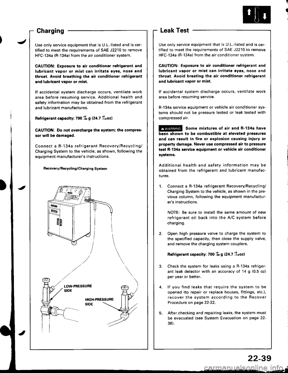
Connect a R-134a refrigerant Recovery/Recycling/
Charging System to the vehicle, as shown in the pre-
vious column, following the equipment manufactur-
er's instructions.
NOTE: Be sure to install the same amount of new
refrigerant oil back into the A/C system before
charging.
Open high pressure valve to charge the system to
the specified capacity, then close the supply valve,
and remove the charging system couplers.
R€frigerani capacity: 700 1o g 124.7 llroz)
Check the system for leaks using a R-134a refriger-
ant leak detector with an accuracy of 14 g (0.5 oz)
per year or better.
lf you find leaks that require the system to be
opened (to repair or replace houses. fittings, etc.),
recover the system according to the Recover
Procedure on page 22-22.
After checking and repairing leaks, the system must
be evacuated (see System Evacuation on page 22-
38).
JUse only service equipment that is U.L.-listed and is cer-
tified to meet the requirements of SAE J2210 to remove
HFC-134a (R-134a) from the air conditioner system.
CAUTION: Exposure to air conditioner r€frigsrant and
lubricant vapol or mist can irritate eyos, nose and
throat. Avoid broathing the air conditioner reftigerant
and lubricant vapor or mist.
lf accidental system discharge occurs, ventilate work
area before resuming service. Additional health and
safety information may be obtained from the refrigerant
and lubricant manufactures.
Retrigerant capscity: 700 % g (2,[.7 i.sozl
CAUTION: Do nol overcharge tho sy3tem; the compres-
sor will b6 damaged.
Connect a R-134a refrigerant Recovery/Recycling/
Charging System to the vehicle, as shown. tollowing the
equipment manufacturer's instructions.
n6covery/Rocycling/Charging Svslem
LOW-PRESSURESIDE
22-39
Page 1136 of 1681
![HONDA INTEGRA 1998 4.G Workshop Manual 1.Remove the dashboard lower cover and knee bolster(see page 23-71],, then disconnect the 2P connector
from the switch.
Check for continuity between the terminals accord-
ing to the table.
2.
3.ll nec HONDA INTEGRA 1998 4.G Workshop Manual 1.Remove the dashboard lower cover and knee bolster(see page 23-71],, then disconnect the 2P connector
from the switch.
Check for continuity between the terminals accord-
ing to the table.
2.
3.ll nec](/manual-img/13/6069/w960_6069-1135.png)
1.Remove the dashboard lower cover and knee bolster(see page 23-71],, then disconnect the 2P connector
from the switch.
Check for continuity between the terminals accord-
ing to the table.
2.
3.ll necessary, replace the switch or adiustthe switch
position (see section 12).
Terminal
cr,t"hP;i
-_\B
RELEASED
PUSHEDoo
Clutch lnterlock Switch TestStarter Solenoid Test
1. Check for continuity between the terminals accord-
ing to the table.
HOLD_ IN COIL
23-79
I
/
-
I
-a
Coil
Teminalt\4sHousing
HOLD INO-o
PULL-INo-o
PULL_ IN COIL
Page 1141 of 1681
Starting System
Armature Inspection and Test (cont'd)
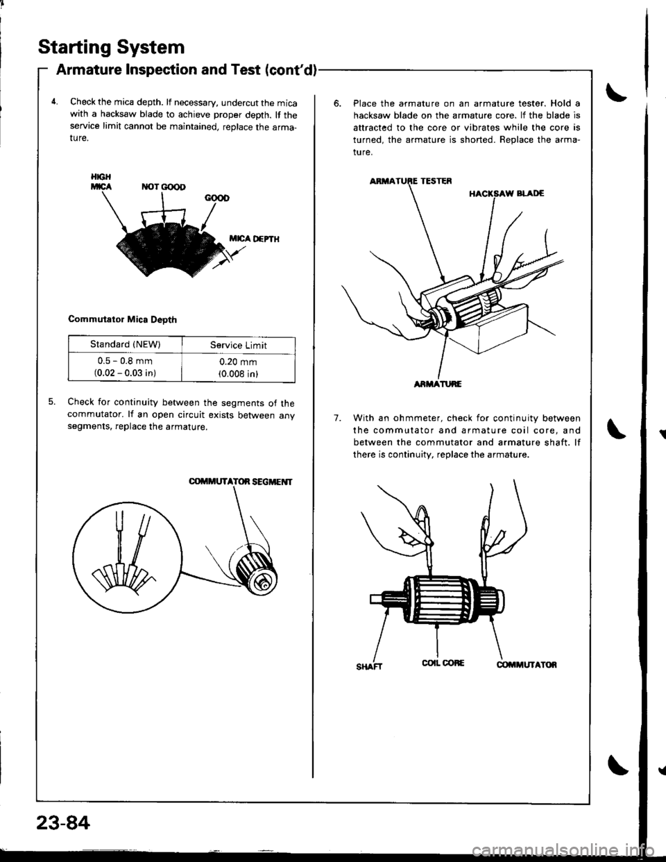
4.Check the mica depth. lf necessary, undercut the micawith a hacksaw blade to achieve proper depth. lf theservice limit cannot be maintained, replace the arma-ture.
Place the armature on an armature tester. Hold a
hacksaw blade on the armature core. lf the blade is
attracted to the core or vibrates while the core is
turned, the armature is shorted. Beplace the arma-
ture.
M|cA D€PTH
Commutator Mica Deoth
5.Check for continuity between the segments of thecommutator. lf an open circuit exists between anvsegments, replace the armature.7.With an ohmmeter, check for continuity between
the commutator and armature coil core, and
between the commutator and armature shaft. lf
there is continuity, replace the armature.
HGH
Standard {NEW)Service Limit
u.5 - u,6 mm(0.02 - 0.03 in)
0.20 mm(0.008 inlARMATURE
Page 1144 of 1681
J
Starting System
Performance Test
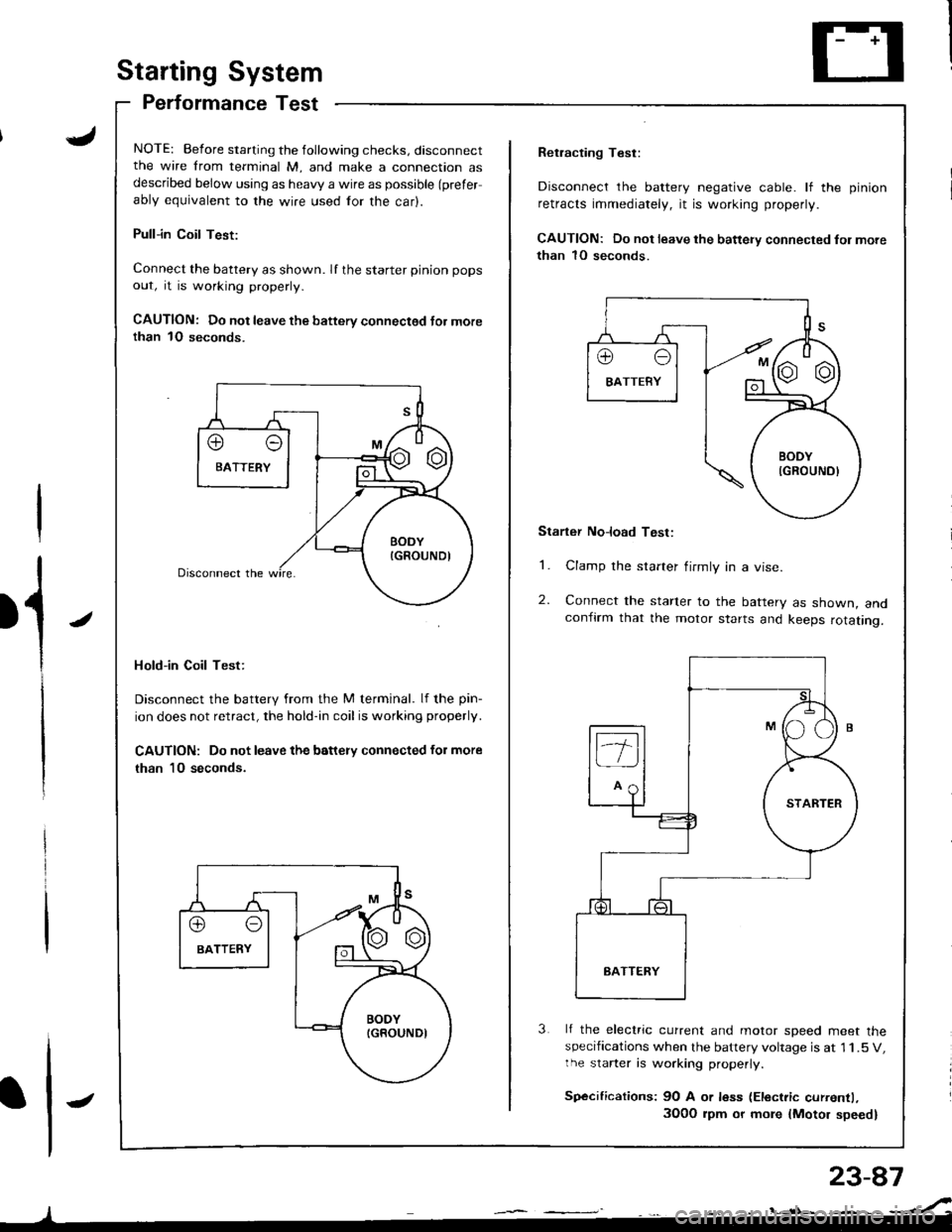
NOTE: Before starting the following checks, disconnectthe wire from terminal M, and make a connection asdescribed below using as heavy a wire as possible (prefer
ably equivalent to the wire used for the car).
Pull-in Coil Test:
Connect the battery as shown. If the starter pinion pops
out, it is working properly.
CAUTION: Do not leave the battery connectsd Jor morethan 1O seconds.
Hold-in Coil Test:
Disconnect the battery from the M terminal. lf the pin-
ion does not retract, the hold-in coil is working properly.
CAUTION: Do not leave the battery connected for more
than 10 seconds.
J
Retracting Test:
Disconnect the battery negative cable. lf the pinion
retracts immediately, it is working properly.
CAUTION: Do not leave the battery connected fol more
than 1O seconds.
Starter No]oad Test:
1. Clamp the starter firmly in a vise.
2. Connect the starter to the battery as shown, andconfirm that the motor starts and keeps rotating.
3 lf the electric current and motor soeed meet thespecifications when the battery voltage is at 1 1.5 V,the starter is working properly.
Sp€cifications: 9O A or less (Electric currentl,
3O0O rpm or more {Motor speed}