1998 HONDA INTEGRA service
[x] Cancel search: servicePage 516 of 1681

Pressure Testing
a While testing, be careJulot the rotating front wheels.
a Make sule litts, iacks, and safety stands are placed
properly (see section 1).
CAUTION: Befoie testing, be sure the transmission fluid
is filled to the proper level.
'1. Raise the vehicle {see section 'll.
2. Warm up the engine (the radiator fan comes on),
then stop the engine and connect a tachometer.
3. Connect the special tool to each inspection hole(s).
TOROUE: 18 N.m l1-8 kgt.m, 13lbf.ftl
CAUTION: Connect the A/T pressure gauge secure-
ly, be sure not to allow dust and olher foreign pani-
cles to enter the inspection hole.
A/T PRESSURE GAUGESET W/PANEL07406 -0020400
A/T LOW PRESSUREGAUGE W/PANEI.07406-OO70300
A/T PRESSURE HOSE,2210 mmOTMAJ _PY4O1 1A{4 Required}
A/T PRESSURE HOSEADAPTER07MAJ -PY40120
l4 Requiredl
NOTE: Use the A/T Pressure Gauge Set (07406-
OO2O0O3) or A/T Low Pressure Gauge (07406-
OOTOOOO), and the A/T pressure gauge hoses and adap-
ters shown above.
4. Start the engine, and measure the respective pres
sures as follows.
a Line Pressure
a Clutch Pressure
a Clutch Low/High Pressure
a Throttle B Pressure
5. Install a new sealing washer and the sealing bolt in
the inspection hole and tighten to the specified
torque.
TOROUE:18 N.m (1.8 kgf.m, 13lbf.ft)
NOTE: Do not reuse old sealing washers; alwaysreplace washers.
Line Pressure Measurement
-1. Set the parking brake, and block both rear wheels
securely.
-2. Run the engine at 2,000 rpm
3. Shift to S or @ position.
4. lMeasure line pressure.
LINE PRESSUREINSPECTION HOLE
LOCK-UP CONTROLSOLENOID VALVEASSEMBLY
PRESSURESHIFT LEVER
POST ONSYMPTOMPROBABLE CAUSEFLUID PRESSURE
StandardService Limit
LineNo,BNo (or low)
Irne pressure
Torque converter,
ATF pump, pressure
regulator, torque
converter check
830 88o kPa
(8.5 9.O kgf/cm'�,
1 20 130 psi)
78O kPa(8.O kgf/cm'�, 1 10 psi)
NOTE: Higher pressures may be indicated if measurements are made in shitt lever positions other than S or f, position.
{cont'd )
14-99
Page 519 of 1681

PressureTesting
{
{cont'dl
\. t,
LOCK-UP CONTROLSOLENOID VALVE
4TH CLUTCH PRESSUREINSPECTION HOLE
u
L
INSPECTION HOLE
INSPECTION HOLE
PRESSURESHIFT LEVER
POStTtONSYMPTOMPBOBABLE CAUSEFLUID PRESSURE
SiandardService Limit
2nd ClutchiorNo or low
2nd pressure
2nd Clutch420 - 880 kPa
(4.3 - 9.0 kgf/cm,,
61 - 130 psi)
varies with throttle
openrng
400 kPa(4.1 kgflcm', 58 psi)
with throttle control
drum released
780 kPa
(8.0 kgflcm'�, 110 psi)
with throttle control
drum more than 1/4
openeo
3rd ClutchNo or low
3rd pressure
3rd Clutch440 - 880 kPa
(4.5 - 9.0 kgf/cm,,
64 - 130 psi)
varies with throttle
opening
4th clutchNo or low
4th pressure
4th Clutch
14-102
v
Page 520 of 1681

lrThrottle B pressure M€asurement
@ while testing, be careful of the rotating
front wheels.
- 1. Allow the front wheels to rotate freely.
- 2. Remove the cable end of the throttle control cable
trom the throttle control drum.
NOTE: Do not loosen the locknuts, simply unhook
the cable end.
THROTTLE CONIBOL DRUM
- 3. Shift to E!] or Oll position.
- 4. Run the engine at 2.000 rpm.- 5. Measure fully-closed throttle B pressure.
-6. Move the throttle control drum to fully-opened
throttle Dosition.- 7. Measure fully-opened throttle B pressure.
THROTTLE B PRESSURE INSPECTION HOLE
PRESSURESHIFT LEVER
POStnONSYMPTOMPROBABLE CAUSEFLUID PRESSURE
StandardService Limit
Throttle B[6ll or JDi]Pressure too
high
Throttle Valve B0 15 kPa(O O.1 5 kgl/cm',
0 2.1 psi)
throttle control drum
fully closed
No or low
Throttle B
pressure
830-88O kPa
(8.5 - 9.O kgf/cm',
1 20 130 psi)
throttle control drum
tully open
780 kPa
(8.0 kgf/cm'�, 1 1O psi)
throttle control drum
fully open
14-103
Page 570 of 1681

1 3. Measure the clearance between the clutch end olate
and top disc with a dial indicator. Zero the dial indi-
cator with the clutch end plate lowered and lift it up
to the snap ring. The distance that the clutch endplate moves is the clearance between the clutch endplate and top disc.
NOTEi Measure at three locations.
Clutch End Plate-to-ToD Disc Clearance:
1 4. lf the clearance is not within the service limits, selecta new clutch end plate from the following table.
NOTE: lf the thickest clutch end plate is installed,but the clearance is still over the standard. replacethe clutch discs and clutch plates.
PLATE NUMEERThickness
ClutchSeNice Limit
lst
2nd
3rd
4th
l st-hold
O.65 -O.85 mm (0.026-O.033 inl
O.65-0.85 mm (0.026 - 0.033 in)
O.40-0.60 mm {O.016-O.O24 in)
O.40-0.60 mm (O.O16 O.O24 in\
O.5O-O.8O mm (O.O2O-O.O31 in)
CLUTCX ENO PLATE
14-153
1ST, 2ND, 3RD and 4TH CLUTCH END PLATE
.lST.HOLD CLUTCH END PLATE
Plate No.Pan Numb€rThickn6ss
I
2
3
4
5
6
7
8
I
10
22551-P56-N00
22552,P56-N00
22553-P56-N00
22554-P56 -N00
22555 -P56- N00
22556 P56 -N00
22557 -P56 - N00
22558 P56-N00
22559-P56-N00
22560-P56- N00
2.1 mm (0.083 in)
2.2 mm (0.087 in)
2.3 mm {0.091 in)
2.4 mm (0.094 in)
2.5 mm (0.098 in)
2.6 mm {0.102 in)
2.7 mm i0.106 in)
2.8 mm (0. 1 10 in)
2.9 mm {0.114 in)
3.0 mm {0.1 18 in)
Plate No.Pan NumborThickness
I
2
3
4
5 (No mark)
6
7
22551-PS5-003
22552 - PS5-003
22553- PS5,003
22554- PS5 -003
22555 PS5-003
22556-PSs 003
22557- PS5-003
2.10 mm (0.083 in)
2.20 mm (0.087 inl
2.30 mm {0.091 in)
2.40 mm {0.094 in)
2.50 mm (0.098 in)
2.60 mm (0.102 in)
2.70 mm (0. 106 in)
Page 620 of 1681

Operational Check
Set the parking brake and block the rear wheels.
Raise the front of the vehicle, and support it with
safety stands in the proper locations (see section 1).
With the engine off, shift the transmission into lstgear,
Rotate either front wheel bv hand and check that
the other wheel rotates in the opposite direction.
lf the opposite tront wheel does not rotste, or if voucannot spin the front wheels at all, the limited slip
differential is faulty and should be roplaced.
Rotating Torque Check
Setting parking brake and block the rear wheels.
Raise the front of the vehicle, and support it with
safety stands in proper locations (see section 1).
With the engine off, shift the transmission into
Neutral.
Measure the rotating torque with a beam-type
torquo wrench in the direction shown, Rotate the
torque wrench morg than two complete turns and
take the maximum reading.
Shift the transmission into 1st gear and measure
the rotating torque again.
Calculate the rotating torque:
Service Limit:
Measur€ment from steD 5
Measurementfrom step 4 =--
For example:
7.8 N.m (0.8 kgf.m)
zg N"ll (03 kgf'ntl = z'ot > z''
Repeat step 3 through 6 for the other wheel.
Replace the limited slip differential assembly if the
rotsting lorque is lower than the service limit.
!
15-23
Page 650 of 1681

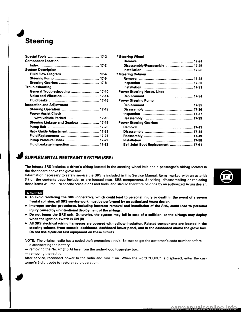
Steering
Componsnt Location
lndox
*Stooring Wheel
Removal ....
Disassombly/Ro8$.mbly
Disassombly ......
F08$€mbly
Powcr Stosring Gosrbox
R6moval
............................ 17-3
............. 17 -1
................ 17-16
............................. 17_25
17-30
17.31
.......17-21
Sy3tom DGcription
Fluid Flow Disgram
Steering Pump .............. 17-5
Stocring Goarbox ...17.8
Troublorhooting
Gonoral Troubleshooting .............................. 17.10
Noiso lnd Vibration ...... 17-1i[
Fluid Losk3
lnspoction
Installation
Powor Steering Hos6, Lino3
Roplacom€nt .................. 17.34
Powor Steoring Pump
RGplac6montlolpeqtion lnd Adiu3tm6nl
Stoo.ing Operation
Powor A$bi Chock
with v.hiclo Parked
Stcering Linkage 6nd Goarbox
Pump Bolt
17.18
17.18
17.19
17-20
17.35
t7-36
17 -37
r7-39
Inspoction
................... 17.41
Rack Guide Adiustmont ..........................-.-.-. 17 -21
Ffuid Rcplacemont ........17-21
Pump Prc&suro Chock ...,........................,..,..., 17 -22
Fluid Leakage Inrpection ............................... 17-23
Dissssembly
R€aEs€mbly
In3tallation........... 17_58
Ball Joint Boot Replacem.ni ........................ 17-61
17-U
17.49
J ,urrar*TNTAL REsrRArNr sysrEM (sRsr
The Integra SRS includes a driver's airbag located in the steering wheel hub and a passenger's airbag located inthe dashboard above the glove box,
Information necessary to safely service the SRS is included in this Service Manual. ltems marked with an asterisk(*) on the contents page include, or are located near, SRS components. Servicing, dissssembling or replacing
these items will require special pr6cautions and tools, and should therefore be done by an authorized Acura dealer.
. To avoid rondoring ths SRS inoparstivo. which could |rad to parsonal iniury or doath in the ov€nt of ! sev6.o
trontal collision, all SRS sarvice work must be perto.med by an authorizod Acura dsalor.. lmpropor 3orvic€ procadures, including inco[6ql rgmoval and inrtallation of the SRS, could l6ad to pgrsonal
iniury clus€d by unintentional doployment of the airbags,. Do nol bump tho SRS unh, (Xherwise, th6 3ystom may fail in cas€ ol a collision, or the airbags may d€ploy
when ths ignition switch is ON {ll).. All SRS electrical wiring harness€s aro covered with yallow insulation. Related component3 are located in ths
stcaring column. tront con3ol6, dashboard, d.shbolrd lower panel, and in the dashboard above ths glove box.
Do not u3o electrical test oquipm€nt on the3e circuii3.
NOTE: The original radio has a coded theft protection circuit. Be sure to get the customer's code number before- disconn€cting the battery.- removing the No. 47 (7.5 A) fuse from the under-hood fuse/relay box,- removing the radio.
After service, reconnect power to the radio and turn it on. When the word "CODE" is displayed. enter the cus-
tomer's 5-digit code to restore radio operation.
Page 652 of 1681

I
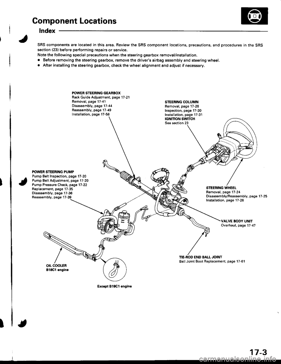
Component Locations
Index
SRS components are located in this area. Review the SRS component locations, precautions, and procedures in the SRSsection (23) before performing repairs or service.
Note the following special precautions when the steering gearbox removal/installation,
. Before removing the steering gearbox, remove the driver's airbag assembly and steering wheel.
. After installing the steering gearbox, ch6ck the wheel alignmentand adjust if necessary.
POWER STEERING GEARBOXRack Guid€ Adjustment, page 17 -21
Removal, pago 17-4'1Disassembly, page 17-44Reassombly. page'17-49Installation, page 17-58
STEEBING COLUMNRemoval. page 17-28Inspection, pago 17-30Installation, page 17-3'1|GNMON SWITCHSee section 23
POWER STEERING PUMPPump Belt Inspection. page 17-20Pump Belt Adjustment, page 17 -20
Pump Pr€ssuro Check, page 17'22Roplacament, page 17-35Dis686embly, page 17-36Reassembly, page 17-39
STEEBING WHEELRomoval, page 17-24Disassembf y/Reassembly, paga 17 -25
Installation, page 17-26
TIE.BOD END BALL JOINTBallJoint Boot Replacement, page 17-61
Exc.pt BlSCl onginc
17-3
Page 667 of 1681

Inspection and Adjustment
Steering Operation
Place the front wheels in the straight ahead position and
measure the distance the steering wheel can be turned
without moving the front wheels.
ROTATIONAL PLAY: 0 - 10 mm {0 - 0.39 inl
lf the play exceeds the service limit. perform rack guide
adiustment (see page 17-211.
lf the play is still excessive after rack guide adjustment.
inspect the steering linkage and gearbox as described
on the neld page.
Power Assist Check with
Vehicle Parked
Check the power steering fluid level (see page 17-
21) and pump belt tension (see page 17-201.
Start the engine, allow it to idle. and turn the steer
ing wheel from lock-to-lock several times to warm
up the fluid.
Attach a spring scale to the steering wheel. With the
engine idling and the car on a clean. dry floor. pull
the scale as shown and read it as soon as the tires
begin to turn,
4. The scale should read no more than 34 N (3.5 kgf,
7.7 lbf). lf it reads more, check the gearbox and
pump.
ROTATIONAL PLAY