Page 1336 of 1681
Precautions/Procedu res
SRS Unit Precautions
Take extra caro when painting or doing body work in
the area below the dashboard. Avoid direct exposure
of the SRS unit or wiring to heat guns, welding, or
spraying equipment.
Disconnect the airbsg connector(s) before discon-
necting SRS harness connectors (see page 23-2851.
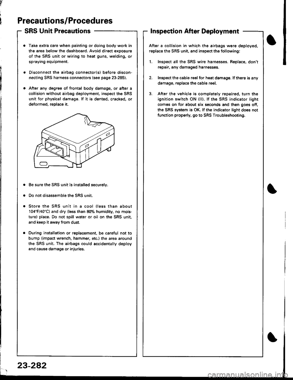
After any degree of frontal body damage, or after a
collision without airbag deployment, inspect the SRS
unit for physical damage. lf it is dented, cracked, or
deformed, reDlace it.
Be sure the SRS unit is installed securelv.
Do not disassemble the SRS unit.
Store the SRS unit in a cool (lass than about
104'F/40"C) and dry (less than 80% humidity, no mois-
ture) place, Do not spill water or oil on the SRS unit,
and keeD it awav trom dust.
During installation or r6placement, be careful not to
bump {impact wrench, hammer, etc.) the area around
the SRS unit. The airbags could accidentally deploy
and cause damsge or injuries,
v
Inspection After Deployment
After a collision in which the airbags w6re deployed,
replace the SRS unit, and inspect the following:
1, Inspect all the SRS wire harnesses. Replace, don't
repair, any damaged harnesses
2. Inspect the cable reel for heat damage. lf there is any
damage. replace the cable reel.
3. After the vehicle is completely repairod, turn the
ignition switch ON {ll). lf the SRS indicator light
comes on for about six seconds and then goes off,
the SRS system is OK. lf the indicator light does not
function properly. go to SRS Troubleshooting.
23-282
Page 1346 of 1681
Troubleshooting
SRS Indicator Light Wire Connections
SRS Indicator Light Power Circuit
To UNDER-DASHFUSE/RELAY BOX2OP CONNECTOB
SRS Indicator Light Control Circuit
To SBS UNIT
iI
SRS MAIN HABNESS
C55'1, C557 : WIRE SIDE OF FEMALE TERMINALS
DASHBOARD WIRE HARNESS
MAIN WIRE HARNESS
C557 -+ To GAUGE ASSEMBLY
CiP7, C449 : TERMINAL SIDE OF MALE TERMINALSC553, CEo1. C802, C804: WIBE SIDE OF FEMALE TEFMINALS
DASHBOAND WIREHARNESS
To UNOEF-DASHFUSE/RELAY BOX2P CONNECTOR
C427 : MAIN WIRE HARNESS 3P CONNECTORC/r49 : MAIN WIBE HARNESS 16P CONNECTORC551 : DASHSOARD WIRE HARNESS 2Op CONNECTORC553 : DASHBOARD WIFE HARNESS t6P CONNECTORCssT : OASHBOARD WlnE HABNESS SP CONNECTOB
To GAUGE ASSEMBLY
C801 : SRS MAIN HARNESS 2P CONNECTOBC802 : SRS MAIN HARNESS 3P CONNECTORC804: SRS MAIN HAFNESS 18P CONNECTOR
BLU
Page 1348 of 1681
Troubleshooting
The SRS Indicator Light Doesnt Come On (cont'd)
From page 23-293
(B)
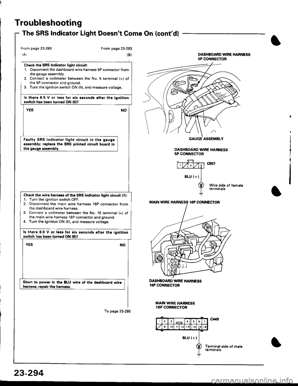
Ch.cl th. SRS indicator light circuit:1. Disconnect the dashboard wire harness 5P connector fromthe gauge assembly.2. Connect a voltmeter belween the No. 5 terminal (+) ofthe 5P connoctor and ground.3. Turn the ignition switch ON {ll}, and measure voltage.
ls the.e 8.5 V or less for six 3econd! rflor lho ignitionswitch h.s be6n turned ON llll?
YESNO
Faulty SRS indicstor light circuit in ihe gtugoassembly; r€pl.co tho SRS printed circuit board inthe gaug. assembly.
Check the wiro ham.ss of tho SRS indicltor light circuh ll l:1. Turn the ignition switch OFF.2. Disconnect the main wire harn€ss 16P connector lromthe dashboard wire harness.3. Connect a voltmeter betlveen the No. 15 torminal {+) ofthe main wire harness 16P connector and ground.4. Turn the ignition ON (ll), and measure voltage.
13 there 8,5 V or lc.r tor 3lx s.condr lftor th. ignitionswitch h.3 boon tuJnod ON llll?
Short to powor In th. BLU wiro ot ths d$hbolrd whahrmess; ropair the hsmo*1.
To pag€ 23-295
DASHBOARD WINE HAR ESS16P CONNECTOR
MAIN WIRE HARI{ESS16P CONNECTOR
From page 23-293
DASHBOAND VUIRC HARNESS5P CONNECTOB
DASHBOARD WIRE HARI{ESS5P CONNECTOR
23-294
Page 1351 of 1681
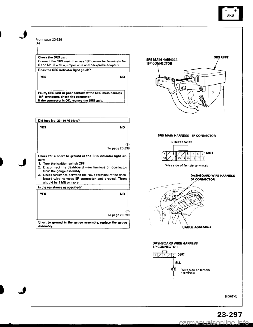
Chcck tho SRS unh:Connect the SRS main harness 18P connector terminals No.6 and No. 3 with a jumper wire and backprobe adapters.
Oos6 th6 SRS indicator liqhi so offl
YESNO
Faulty SRS unit or poor contact at the SRS main hamoi318P connector; check lhe connactor.Ittho connector i3 OX, replaco the SRS unit.
Did fuse No.23 {10 Al blow?
YESNO
(B)
To page 23-298
Chock tor a short to ground in thc SRS indic.tor light ci.-cuit:1. Turn the ignition switch OFF.2. Disconnect the dashboard wire harness 5P connectorfrom the gauge assembly.3. Check resistance between the No. 5 terminal of the dash-board wire harness 5P connector and ground. Thereshould be 1 MO or more.
ls the resistance as apocifiad?
YESNO
{c)To page 23-299
Short to ground in tho gauga aatambly; raplace tho gaugeasscmblY.
From page 23-296(A)
SRS MAIN HARNESS 18P CONNECTOR
JUMPER WIRE
)
oasrSoAno unRE HARt{Ess5P @ilFCTOn
GAUGE ASSEMBLY
DASHAOARD WIBE HARNESS5P CONNECTOR
ffiv;1"u*---.--a
] sru
O wire side of female
I terminals
)(cont'd)
UNITsRs
Wire side of female lerminals
f,t
r
23-297
Page 1352 of 1681
Troubleshooting
The SRS Indicator Light Doesn't Go Off (cont'd)
From pags 23-297(8)
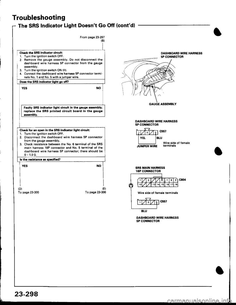
ch.ct tha SRS indicrtor circuit:1. Turn tho ignition switch OFF.2- Remove the gauge assembly. Do not disconnoct thedashboard wire harnosg 5P connector from the gaugg
assemblY.3. Turn the ignitjon switch ON {ll).4. Connect the dashboard wire hrrng6a 5P connector torminals No. I and No.5 with a iumoerwire.
Doe3 th. SRS indicator lisht go otf|
NOYES
Faulty SRS indic.tor light circuh in th. g.ug. r*t mbly;raplroe th. SRS prini.d ciJcuit bolrd in th. g.ug.
9$emblY.
ch.ck loi .n op.n in th. SRS indicltor ligl|t circuh:1. Turn the ignition switch OFF,2, Disconn€ct the dashboard wire harnoss 5P connectorfrom th6 gauge assembly.3. Check resistanco between ths No. 6 t€rminal ot the SRSmain harneas 18P conngctor and No. 5 terminal of th6dashboard wire harness 5P connector; there should bs0-1.00.
lr tha raaidanca aa lpacifiad?
YESNO
(D)
To page 23-300
(E)
To page 23-300
DASHBOARD WIRE HARNESS5P COt{t{ECTOR
SRS MAIT{ HARNESSt8P CON ECTOR
OASHBOARD WIRE HARI{ESS5P COI{NECTOR
OASHBOABD WIRE HARNESS5P CONNECTOR
rt#z;trxistL,iry
lYEr lBruWir6 sido oI fomaleJUMPER W|RE terminals
GAUGE ASSEMBLY
W 6 side of lemale terminals
23-298
Page 1353 of 1681
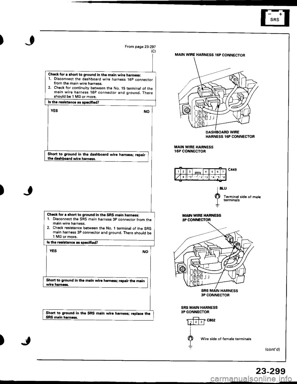
)From page 23-297(c)MAIN w|RE HARNESS lEP CONNECTOR
HARNESS
MAII{ WINE HABTESS16P COt{ItECTOR
16P CONNECTOR
C,!r9
lo'
O T6rrninalside ot matc
I rermrnEts
3P CONNECTOR
SRS MAIN HARNESS3P CONNECTOR
(cont'd)
Chack for a 3hort to ground in tha main wira harnr$:1. Disconn€ct the dashboard wire harness .l6p connectorfrom the main wire ha.ngss.2. Chock for continuity between the No. t5 terminal ot themain wiro harness 16P conngctor and ground. Therethould b€ 1 M0 or more.
L tha rcrbianca ra apacifiad?
YESNO
Short to groond in th6 d8hboard wirc hrJn.3!; ropairth. d!.hborrd wir. h.ma.!.
Chacl lor a rhort to ground in tha SRS main h!]no3s:1. Disconnect th6 SRS main harness 3p connector lrom themain wir€ harness.2. Chock resistance betwoen the No. I terminal of the SRSmain harngss 3P connoctor and ground. There should be1 M0 or more.
l! tho raainanca ar apacifiad?
YESNO
Short to g.ound in dta main wil. h!m6a; raprir tha mainwira hamas.
Shon to ground in tho SRS mlin wira hlrna*t rcplaca thcSRS mlin harnas.
2567
92'5 6
)
MAIN WIRE HAFNESS3P COI{I{ECYOR
)
Wire side ot lemale torminals
23-299
Page 1354 of 1681
Troubleshooting
The SRS Indicator Light Doesn't Go Off (cont'dl
23-300
t
Fro- !'age 23'298lDASHBOARD WIRE HARNESS5P CONNECTOR
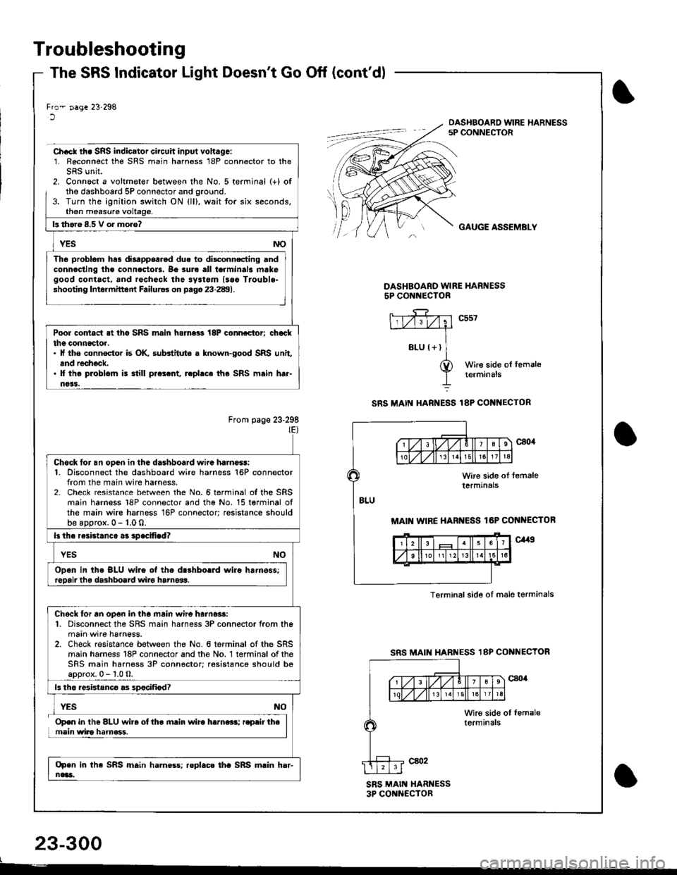
Ch.ct rh. SRS indicator circuh input vohagei1. Reconnect the SRS main harness 18P connector to theSRS unit.2. Connoct a voltmeter between the No. 5 terminal (+) ofthe dashboard 5P connector and oround.3. Turn the ignition switch ON lll), wait tor six seconds,then measure
GAUGE ASSEMBLY
DASHBOARO WIRE HARNESS5P CONl{ECTOR
c557
Wire side ol femaletermrnals
SRS MAI[{ HARNESS 18P COI{I{ECTOR
From page 23-298(E)
SRS MAII HARI{ESS 18P CONNECTOR
SRS MAIN XARI{ESS3P CONNECTOR
f'l! thor6 8.5 V o. mo.e?
Tho problom has disappearod due to disc_onnscting andconnacting tha connectols. Be sure all torminal3 makegood contact, and rechock the sy3tom lsaa Trouble-shooting Intormittont Failurss on pago 23-289).
Poor contact at tho SRS main hamess 18P conncctor; chatclthe conn6c'toa.. lf the connocto. is OK, substitute a known-good SRS unit,and rechock.' It the problom is still prescnt, r.phca the SRS main har-noas.
MAI WIRE HARNESS lGP CONNECTOR
Terminalsid€ ol male terminals
Chock tor an ooen in the dashboard wire haino*!:1. Disconnect the dashboard wire harness 16P connectorfrom the main wire harness.2- Check resistance between the No.6 terminal ofthe SRSmain harness 18P connector and the No. 15 terminal olthe main wire harness 16P connector; resistance shouldbe aDorox. 0 - 1.0 0.
ls th. resistanco a3 spacifigd?
Open in th. BLU wir6 of the drshborrd wirc harnsss;
Chock for an op6n in tha main wire harn6$:1. Disconnect the SRS main harness 3P connector from themain wire harness.2. Check resistance between the No. 6 terminal of the SRSmain harness 18P connector and the No. 1 terminal of theSRS main harness 3P connector; resistance should boaoorox.0-1.0O.
13 th6 r6ktanca as 3pocifiod?
Open in the SRS main ha.n$s; roplac. tha SRS main hsr-nai!i.
Open in the BLU wir. oltha mrin wirc harna.s; r.pair themain wiao hamoss.
Page 1355 of 1681
)
DTC 1-1 and DTC 1-2
CAUTION: Whenever the ignition switch is ON {lll, or
has been turned OFF for less thsn three minutes, be
ca.eful not to bump the SRS unit; the airbags could
accidentally deploy and cause damage or iniuries.
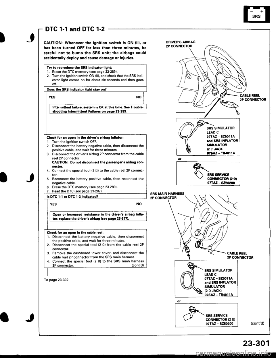
CABLE REEL2P CONNECTOR
SRS SIMULATORL€AD CoTtaz - s6011Alrd Sns IYFLATORg.prToR
o ! Jrcxatllil - n olrl
*.t sns savE\,' colltcroe c o07TAZ-8E@
CABLE BEEL2P CONNECTOR
SRS SERVICEGoNNECTOR (2 0l
07TAZ - 5250200(cont'd)
Try to roproduce the SRS indicator light:1. Erase the DTC memory lsee page 23-289).2. Turn the ignition switch ON (ll), and check that the SRS indicator light comes on tor about six seconds and then goes
ofJ.
Do€s the SRS indicator light stay on?
YES
h6rmittar'rt Lalul!, 3yrtdll b o|( rt thb tiiru. 5€6 lroubl6-ahootino lmarmitlant Failura. on o.oa 23-289.
Chock fo. an opGn in the dlivgl's cirbag infirtor:'1. Turn the ignition switch OFF.2. Disconnect the battery negative cable, then disconnect thepositive cable, and wail for thrce minutes.3. Disconnect the driver's airbag 2P connectorlrom th€ cablereel 2P connector-CAUTION: Do not disconnoct tho palF€nger'r .ilb.g con-nector.4. Connect the sDecial tool 12 o) to the cable reel 2P connec-tor.5. Reconnect the bsftery positive cable, then reconn€ct thonegative cable.6. Erase the DTC memory (se€ page 23-289).7. Bead the DTC (see page 23-2811.
ls DTC 1-1 oI DTC 1-2 indic.tod?
YESNO
Opon or incro8od r.rist.nco in tho driv6.'3 airbag inf+
lor; replacs tho drivor'3 rirb.g lsoe prgg 23-317).
Ch.ck for an op6n in the cablo re.l:1. Disconnect the battery negativo cabl6, thon disconnectthe positive cable, and wait for three minutes.2. Disconnect the soecial tool (2 o) from rhe cable reel 2Pconnector.3. Remove the dashboard lower cover. and disconnoct thecable reel2P connectorfrom the SRS main harness.4. Connect tho special tool (2 0) to thg SRS main harness2P connector. (cont'dl
To page 23-302
SRS SIMULATOR|.EAO C07TAZ - Si4tor lAand SRS INFLATORSIMULATOR(2 0 JACK)
23-301