Page 1193 of 1681
MAINTENANCE BEMINDER LIGHT{ln the gauge assembly)Gauge Assembly. page 23-120
VEHICLE SPEED SENSOR IVSS)(On th6 transmission housing)Test, page 23-128, 129Replacement, page 23-130
MAIMTENANCE REMINDER UNIT(Behind th€ dashboard lower cover)Input T6st, page 23-139
Maintenance Reminder System
Component Location Index
\
t
23-136
I
Page 1194 of 1681

t
{)
)
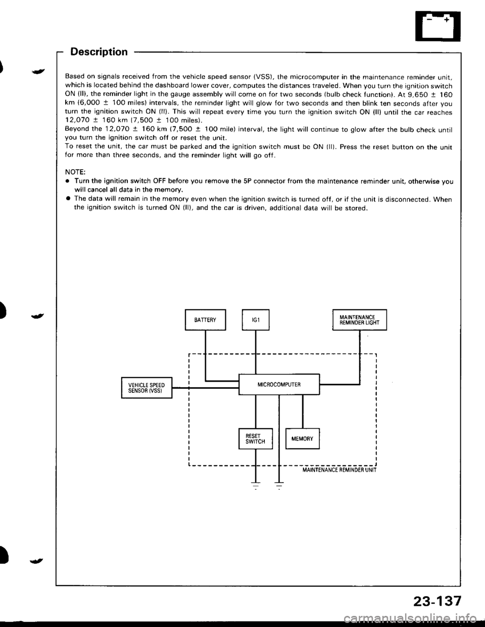
Based on signals received from the vehicle speed sensor (VSS). the microcomputer in the maintenance reminder unit,which is located behind the dashboard lower cover, computes the distances traveled. When you turn the ignition switchON (ll), the reminder light in the gauge assembly will come on for two seconds (bulb check tunction). At 9,650 1 160km {6,000 1 1O0 miles} intervals, the reminder light will glow for two seconds and then blink ten seconds after you
turn the ignition switch ON (ll). This will repeat every rime you turn the ignition switch ON {ll) until rhe car reaches12,O7O ! 1 60 km (7,500 t 100 miles).
Beyond the 12.o1O ! 160 km (7,5OO t IOO mile) interval, the light will continue to glow after the bulb check untilyou turn the ignition switch otf or reset the unit.
To reset the unit, the car must be parked and the ignition switch must be ON (ll). Press the reset button on the unitfor more than three seconds, and the reminder light will go off.
NOTE:
. Turn the ignition switch OFF before you remove the 5P connector from the maintenance reminder unit, otherwise vouwiil cancel all data in the memory.
a The data will remain in the memory even when the ignition switch is turned off, or if the unit is disconnected. Whenthe ignition switch is turned ON (lll, and the car is driven, additional data will be stored.
{
23-137
Page 1199 of 1681
A/T Gear Position Indicator
Indicator Input Test
Remove the gauge assembly from the dashboard (see
page 23-1261, and disconnect connectors "8", "C" and"D" from it. Inspect the connector terminals to be sure
they are all making good contact.
a lI the terminals are bent, loose or corroded, repair them
as necessary, and recheck the system.a lI the terminals look OK, make the following input tests
at the connector.- l{ any test indicates a problem, find and correct the
cause, then recheck the system.
lf all the input tests prove OK, the gauge assem-
bly must be faulty; replace it.
CONNECTOR "B"
=------'\-\-\\---- =
23-142
Page 1207 of 1681

Interlock System
Key Interlock SolenoidTest
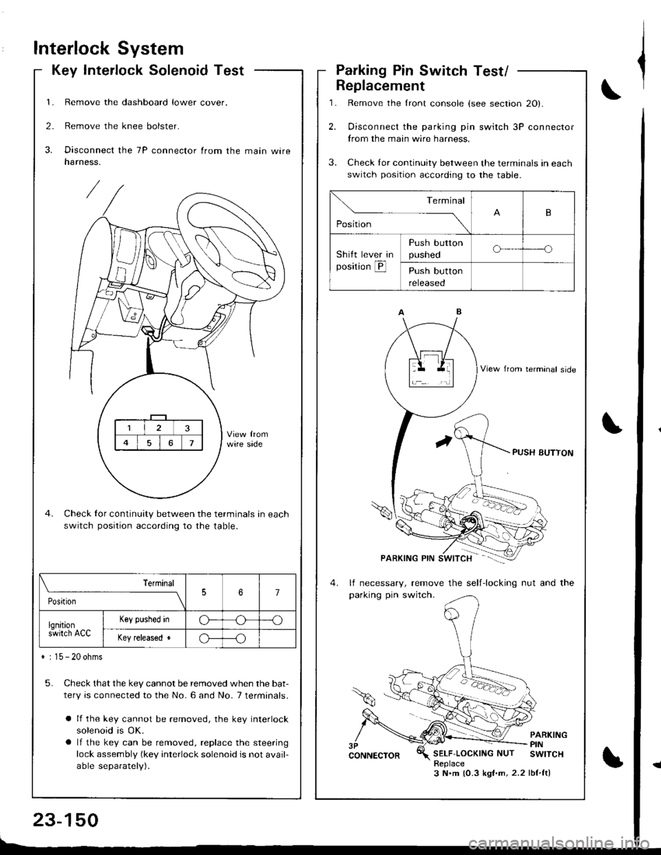
1. Remove the dashboard lower cover.
2. Remove the knee bolster.
3. Disconnect the 7P connector from the main wireharness.
Check for continuity between the terminals in each
switch position according to the table.
5. Check that the key cannot be removed when the bat-
tery is connected to the No. 6 and No. 7 terminals.
a lf the key cannot be removed, the key interlock
solenoid is OK.
a lf the key can be removed, replace the steering
lock assembly (key interlock solenoid is not avail-
able separately).
\_____,___ ___l
PositionJ7
lqnitions-wirch ACC
Key plshed inG---o
Key released *o---o
* : 15 - 20 ohms
,l
\,
Parking Pin Switch Test/
1.
2.
Replacement
3.
Remove the lront console (see section 20).
Oisconnect the parking pin switch 3P connector
from the main wire harness.
Check Ior continuity between the terminals in each
switch position according to the table.
lf necessary, remove the self-locking nut and the
parking pin switch.
PARKINGPINSELF'LOCKINGNUT SWITCHReplace3 N.m {0.3 kgf.m,2.2 lbf.ft)
Terminal
,o"n*
-- ---_\B
Shitt lever in
position @
Push button
pusneoo-----o
Push button
reteaseo
Page 1211 of 1681

Integrated Control Unit
Input Test
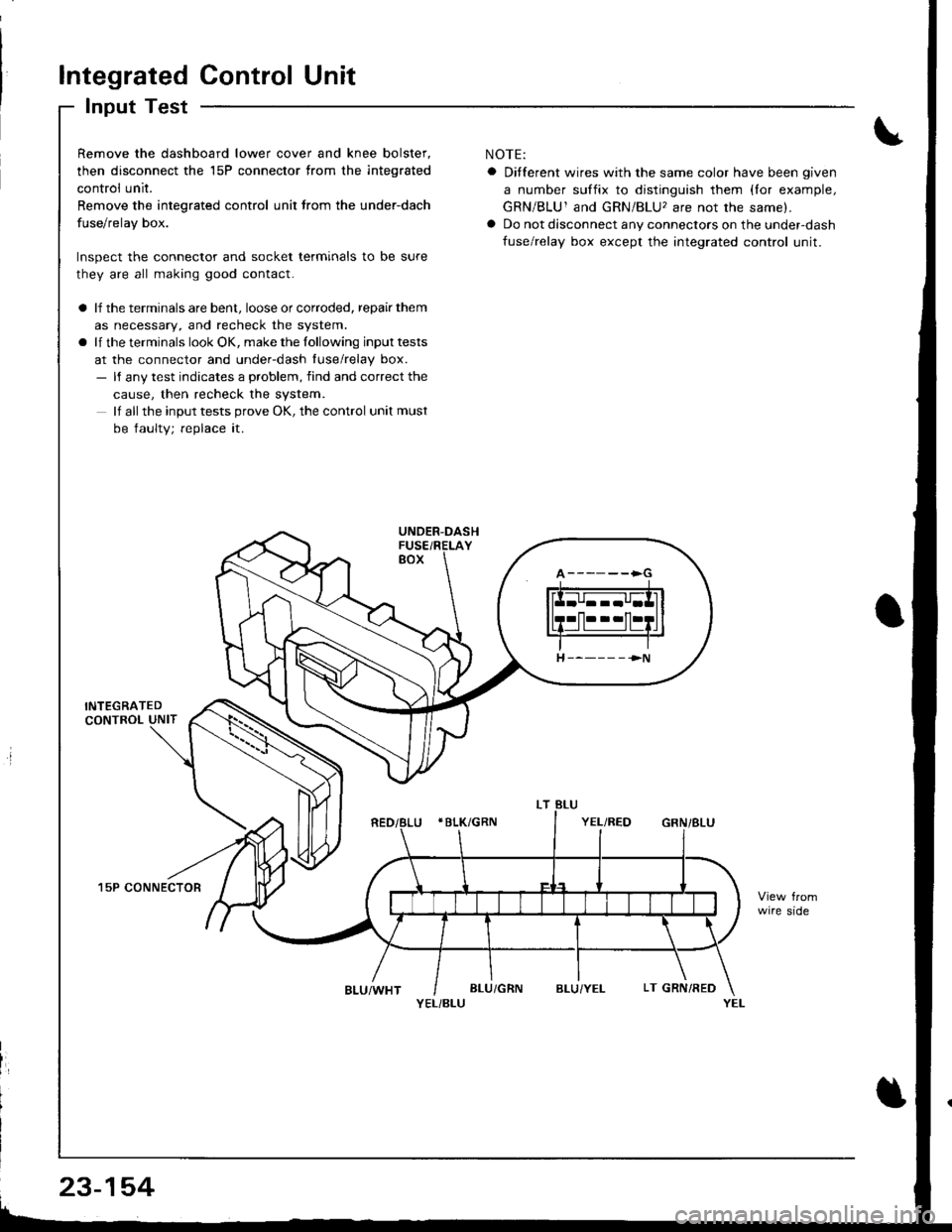
Remove the dashboard lower cover and knee bolster,
then disconnect the 15P connector trom the integrated
control unit.
Remove the integrated control unit lrom the under-dach
fuse/relay box.
Inspect the connector and socket terminals to be sure
they are all making good contact.
a lf the terminals are bent, loose or corroded, repair them
as necessary, and recheck the system.
a lf the terminals look OK, make the lollowing input tests
at the connector and under-dash luse/relay box.- ll any test indicates a problem, find and correct the
cause, then recheck the system.
lf all the input tests prove OK, the control unit must
be faulty; replace it.
15P CONNECTOR
NOTE:
a Ditferent wires with the same color have been given
a number suffix to distinguish them (lor example,
GRN/BLU1 and GRN/BLU, are not the same).
a Do not disconnect any connectors on the under-dash
fuse/relay box except the integrated control unit.
wire side
YEL/BLU
A------>G
H ----- - ->N
23-154
Page 1221 of 1681
Lighting System
Daytime Running Lights Control Unit Input Test (Ganada)
Remove the dashboard lower cover and knee bolster.
Disconnect the connectors from the daytime running
lights control unit.
Inspect the connector and socket terminals to be
sure they are all making good contact.
a lf the terminals are bent, loose or corroded. repair
them as necessary, and recheck the system.
a ll the terminals look OK. make the lollowing in-
put tests at the connector.
lf any test indicates a problem, find and cor-
rect the cause, then recheck the system.
lf all the input tests prove OK, the control unit
must be faulty; replace it.
4P CONNECTOR8P CONNECTOR
GNN/RED
WHTiRED
WHT/YEL
REO/WHTRED/GRN
YEL/BLK
23-164
View trom wire sideView from wire side
Page 1223 of 1681
Lighting System
Combination Light/Turn Signal Switch Test
Remove the dashboard lower cover and steering
column covers {see page 23-721.
Disconnect the 4P and 7P connectors from the
switch.
Check the connector and socket terminals to be sure
they are all making good contact. lf the terminals are
bent, loose, or corroded, repair them as necessary,
and recheck the system.
Check lor continuity between the termanals in each
switch position according to the table.
B
D
E
H
4P CONNECTOR
7P CONNECTOR
23-166
Page 1236 of 1681

J
)
'1.
3.
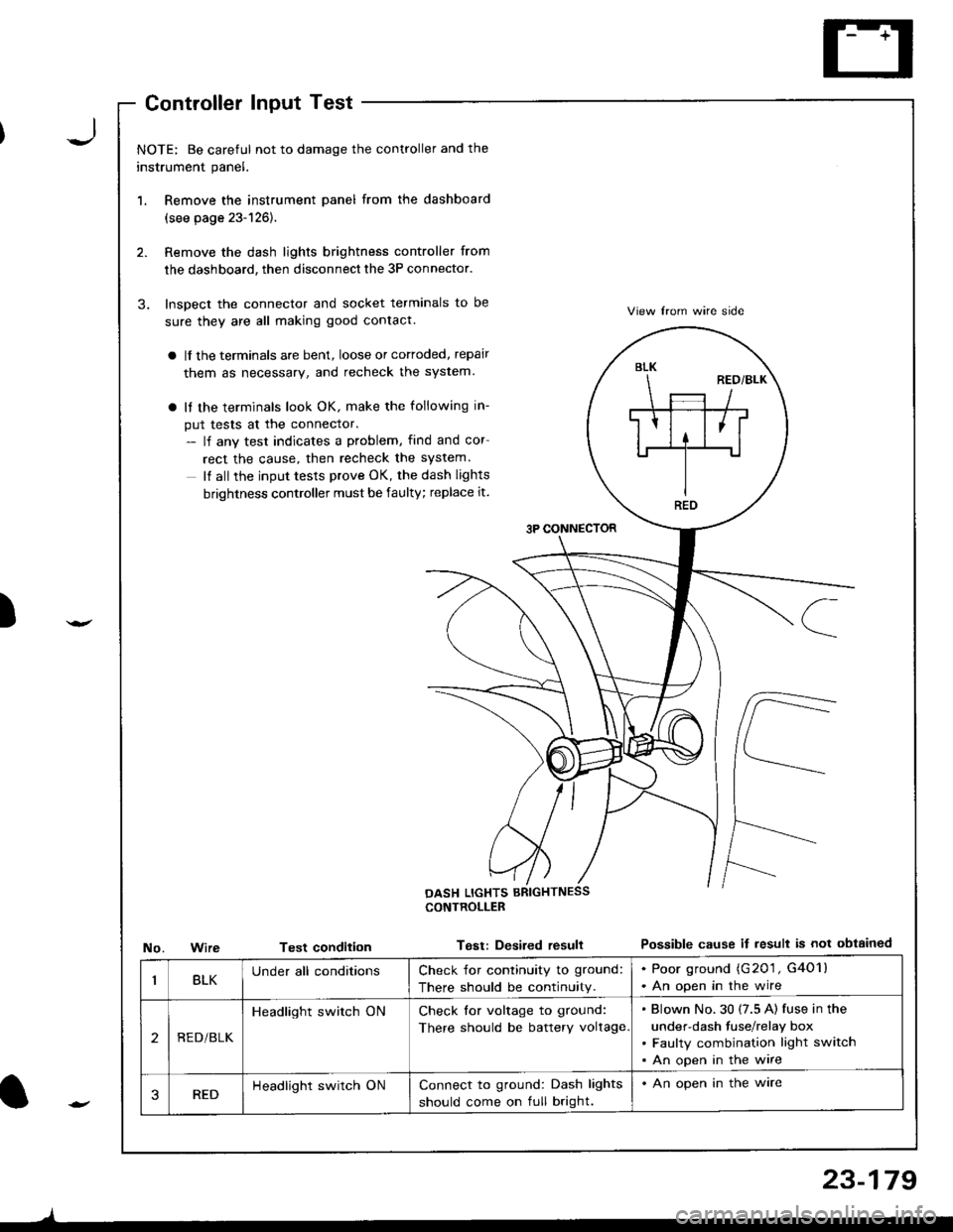
NOTE: Be careful not to damage the controller and the
instrument panel.
Remove the instrument panel from the dashboard
(see page 23-126).
Remove the dash lights brightness controller from
the dashboard, then disconnect the 3P connector.
Inspect the connector and socket terminals to be
sure they are all making good contact.
a lf the terminals are bent, loose or cortoded, repair
them as necessary, and recheck the system.
a It the terminals look OK, make the following in-
put tests at the connector.- lf any test indicates a problem, find and cor
rect the cause, then recheck the system.
It all the input tests prove OK, the dash lights
brightness controller must be faulty; replace it.
3P CONNECTOR
View lrom wire side
Possible cause if result is not obtainedNo.WireTest condition
CONTROLLEB
Test: Desired resull
BLK
REO
BLKUnder all conditionsCheck for continuity to ground:
There should be continuity.
. Poor ground (G201 , G4O1l. An open in the wire
2REDi BLK
Headlight switch ONCheck for voltage to ground:
There should be battery voltage
Blown No.30 (7.5 A) fuse in the
under-dash fuse/relay box
Faulty combination light switch
An open in the wire
3REDHeadlight switch ONConnect to ground: Dash lights
should come on full bright.
. An open in the ware
l-
)
23-179