Page 1263 of 1681
Clock
CircuitDiagram
CAUTION:
a Prv the clock out at the left side.
a Be careful not to damage the clock and the dashboard
when prying the clock out.
1. Pry the clock out from the dashboard. then discon-
nect the 4P connector.
4P CONNECTOR
CLOCK
BATTERY
UNDER,HOODFUSE/RELAYBOX
WI-]T/BLK
I
A/ BAT I 1GN TION
Y*"t No3o(7.sA)-|" -v
F'nrrn l
I
WHT/BLU
l- wHT 8LU
al-
STEREO BADIOiCASSETTE PLAYEF
BLK
G201G401
BLKGround
BYELrG1
pry,
(Main clock power sup-
cRE D/BLKLights-on signal
DWHT/BLUConstant power
(Time memory)
Terminals
23-206
Page 1266 of 1681

SwitchTest
SRS comDonents are located in this area. Review the
SRS component locations, precautions, and procedures
in the SRS section (23) before performing repairs or ser-
vtce.
NOTE: The original radio has a coded thett protection cir-
cuit. Be sure to get the customer's code number beJore- disconnecting the battery.- removing the No. 47 (7.5 A) fuse from the under-hood
fuse/relay box.- removing the radio.
After service, reconnect Dower to the radio and turn it on.
When the word "CODE" is displayed, enter the customer's
5-digit code to restore radio operation
Disconnect the battery negative cable, then discon-
nect the positive cable, and wait at least three min-
uIes.
Disconnect each airbag connector.
Driver's Side:
a Remove the access panel from the steering wheel,
then disconnect the 2P connector between the
driver's airbag and cable reel.
Front Passenger's Side:
. Remove the glove box,
a Disconnect the 2P connector between the front
passenger's airbag and SRS main harness.
1.
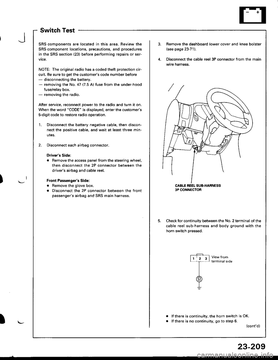
Remove the dashboard lower cover and knee bolster(see page 23-71).
Disconnect the cable reel 3P conneclor from the main
wtre narness.
CABLE REEL SUB.HARNESS3P CONNECTOR
Check for continuitv between the No. 2 terminal of the
cable reel sub-harness and body ground with the
horn switch Dressed.
terminalside
a
It there is continuity, the horn switch is OK.
lf there is no continuity, go to step 6. (cont,d)
r-P r11 2 3l-t-
I
I\-J
)
I
23-209
Page 1279 of 1681

Moonroof
Function Test
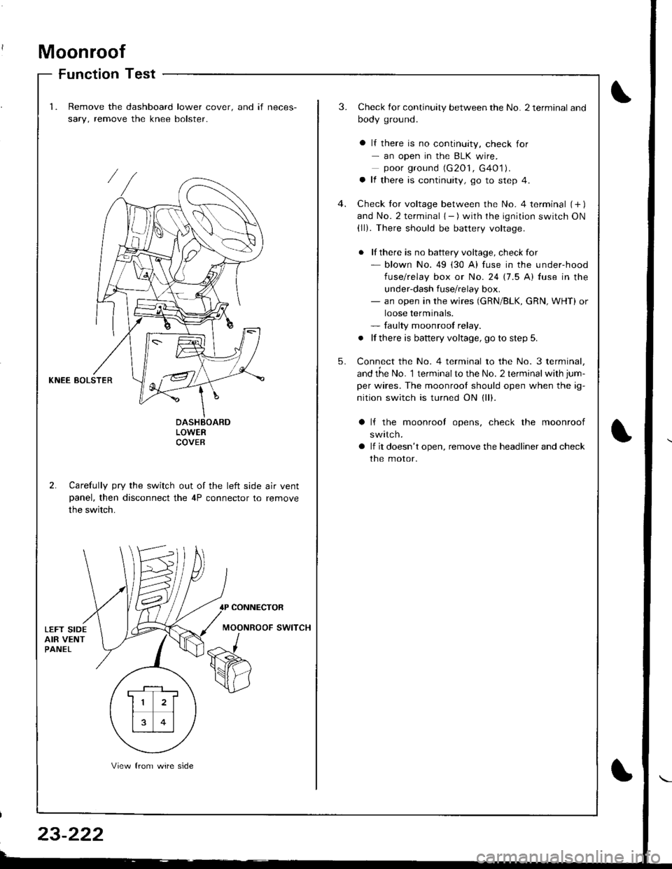
1.Remove the dashboard lower cover. and if neces-
sary, remove the knee bolster.
3.Check for continuity between the No. 2 terminal and
body ground.
a lf there is no continuity, check for- an open in the BLK wire.poor ground (G2O1, G4O1).a lf there is continuity, go to step 4.
Check tor voltage between the No. 4 terminal (+ )and No. 2 terminal { - ) with the ignition switch ON(ll). There should be battery voltage.
. lf there is no battery voltage, checkfor- blown No. 49 (30 A) fuse in the under-hood
fuse/relay box or No. 24 17.5 Al fuse in the
under-dash fuse/relay box.- an open in the wires (GRN/BLK, cRN, WHT) or
loose terminals.- faulty moonroof relay.
. lf there is battery voltage, go to step 5.
Connect the No. 4 terminal to the No. 3 terminal,
and the No. 1 terminalto the No. 2 terminal with jum-
per wires. The moonrool should open when the ig-
nition switch is turned ON (ll).
4.
5.
KNEE BOLSTER
LOWERCOVEB
2. Carefully pry the switch out of the left side air ventpanel, then disconnect the 4P connector to remove
the switch.
lf the moonrool opens, check the moonroof
swttcn.
lf it doesn't open, remove the headliner and check
the motor.
CONNECTOR
MOONROOF SWITCH
. F-_1 ,
11 2l
rt�1
13 0l
View from wire side
Page 1280 of 1681
Terminal
;'..b;--\BcD
OFFCF--o
OPENO--_oo--_o
CLOSEo-_O
o-o
Switch Test
Remove the dashboard lower cover.
Carefully pry the switch out of the left side ajr ventpanel, then disconnect the 4P connector and remove
the switch.
Check for continuity between the terminals in each
switch position according to the table.
MOONROOF SWITCH
1.
2.
Motor Test
Remove the headliner (see section 20).
Disconnect the 2P connector from the moonroof
moror.
Check the motor by connecting power and ground
according to the table.
NOTE: Motor clutch test is in section 20.
{Hatchbackl {Sedanl
View from terminal side
lf the motor tails to run or does-: run smoothly,reptace rt.
)
)
Terminal
Conditbn - ll\B
OPENoo
CLOSEoo
,l
\{J\,, CLOSE
?
IOPENOFF
23-223
Page 1312 of 1681
ControlInputTestUnit
'LRemove the dashboard lower cover and knee bolster(see page 23-71).
Disconnect the 14P connector from the control unit.
Inspect the connector and socket terminals to be
sure they are all making good contact.
a lf the terminals are bent, loose or corroded, repair
them as necessary, and recheck the system.a lf the terminals look OK, make the following input tests at the connector.
It any test indicates a problem, find and cor-
rect the cause, then recheck the system.
lf allthe input tests prove OK, the control unit
must be faulty; replace it.
3.
CRUISE CONTROL UNIT
View from w re s ce
(cont'd)
LT GRN/RED
14P CONNECTOR
)
23-257
Page 1314 of 1681

Set/Resume Switch Test/Replacement
SRS comDonents are located in this area. Review the
SRS component locations, precautions, and procedures
in the SRS section (23) before performing repairs or ser-
vice.
NOTE: The original radio has a coded theft protection cir-
cuit, Be sure to get the customer's code number before- disconnecting the battery.- removing the No. 47 {7.5 A} fuse from the under-hood
fuse/relav box.- removing the radio.
Atter service, reconnect Dower to the radio and turn it on.
When the word "CODE" is displayed, enter the customer's
s-digit code to restore radio operatior..
1. Disconnect the battery negative cable, then discon-
nect the oositive cable, and wait at least three min-
utes,
2. Disconnect each airbag connector.
Drivor's Side:
a Remove the access panel from the steering wheel,
then disconnect the 2P connector between the
driver's airbag and cable reel,
Front Passenge;'s Side:
a Remove the glove box.
. Disconnect the 2P connector between the front
passenger's airbag and SRS main harness.
)
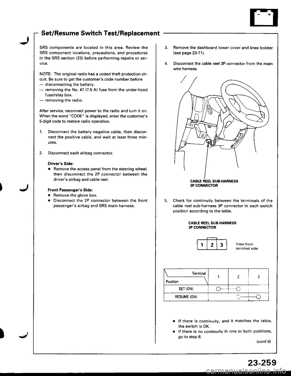
Remove the dashboard lower cover and knee bolster(see page 23-71).
Disconnect the cable reel 3P connector trom the main
wire harness.
CABLE REEL SU&HARNESS3P CONNECTOR
Check for continuiw between the terminals of the
cable reel sub-harness 3P connector in each switch
position according to the table.
CAALE REEL SUB.HARNESS3P CONNECTOR
terminalside
lf there is continuity, and it matches the table,
the switch is OK.
lf there is no continuity in one or both positions,
go to step 6.(cont'd)
Terminal
t"*-
---\23
SET {ON)oC
RESUME (ON}o
23-259
Page 1316 of 1681
Main Switch Test/Replacement
J)
JI
I
NOTE: Be careful not to damage the switch and the in-
strument panel.
1. Remove the instrument panel from the dashboard(see page 23-126).
2. Remove the switch from the dashboard. then dis-
connect the 5P connector,
3. Check for continuity between the terminals in each
switch position according to the table.
a lf there is no continuity in any position, replace
the switch.
Teminal
;""Jt- \ttcD
OFFo-/a\-o/.:\-o\:.7\:./
ONo*/:\-oo--o\:,,/\-/
ABCDE
J
23-261
Page 1332 of 1681
!
Gomponent/Wiring Locations Index
SRS INDICATOR LIGHT(ln the gauge assembly)Troubleshooting, page 23-287Gauge assembly, page 23-126
To HORN SWITCH
CABLE REELReplacement,page 23-322
DRIVER'S AIRBAGReplacement. page 23-317Disposal, page 23-320To DRIVER'S AIRBAG
DASHBOARD WIRE HARNESSFRONT PASSENGER'SAIRBAGBeplacement, page 23-317Disposal, page 23-320
to SRS INDICATOR LIGHT in GAUGE ASSEMBLY5P CONNECTOR
SRS MAIN HARNESSTo MAINWIRE HARNESS3P CONNECTOR
SRS MAINHARNESSto UNDER-DASHFUSE/RELAYBOX2P CONNECTOR
HARNESSto FRONT PASSENGERS AIRBAG2P CONNECTOR
SRS MAIN
SERVICE CHECXCONNECTOR {2PIIBRNAAIHT, BLK]to CABLE REEL2P CONNECTOR
MAIN WIRE HARNESSto DASHBOARD WIREHARNESS16P CONNECTOR
ERASE SIGNAL (MES}SRS UNITGBOUNOSRS MAIN HARNESSSRS UNIT(lncluding safing sensorano rmpact sensor)R6placement, page 23-326
2P CONNECTORSRS MAIN HARNESSto SRS UNIT18P CONNECTOR
S\--0
[GRN, GRNI or IWHT, BLKI
23-27A