1998 HONDA INTEGRA dashboard
[x] Cancel search: dashboardPage 1357 of 1681
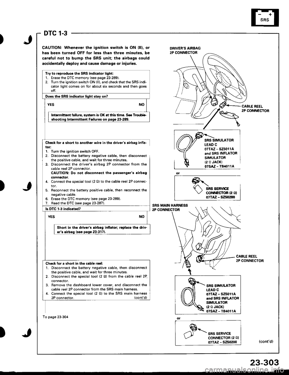
DTC 1-3
)
CAUTION: When€ver the ignition 3witch is ON (ll), or
has been turned OFF for le3s lhan three minute3, be
careful not to bump the SRS unit; the airbags could
accidontally d€ploy and cause damage or iniuries.
Chcck for a short to anothor wiro in the driver's airbag inlla-tor:1. Turn the ignition switch OFF.2. Disconnect the battery negative cable, then disconnectthe positive cable, and wait tor three minutes.3. Disconnect the driver's airbag 2P connector from thecable reel 2P connector.CAUTION: Do not diaconnocl the p.sseng.r'5 !irbaOconnoctor.4. Connect the special tool {2 o} to the cable reel 2P connec'tor,5. Reconnect the battery positive cable, then reconnect thenegative cable.
SRS SIMULATORLEAD C0?TAZ - SZ5011Aand SRS INFLATORSIMULATORt2 0 JACKI07SAZ - T8,(}11A
)
Erase the DTC memory (see page 23-2891.Road the DTC (see page 23-287).
o1
,"" rr*u,".GoNNECTOR 12 0)
07TAZ - S250200(cont'd)
SRS SIMULATORI.EAD CorTAZ - SZ5011A.nd SRS INFLATORSIMULATOR12 0 JACKI07SAZ-TBrl011A
TrVto reproduce the SRS indicator light:1. Erase the DTC memory (see page 23-289).2. Turn the ignition switch ON (ll), and checkthatthe SRS indicator light comes on for about six seconds and then goesoff.
Doss tho SRS indicato. liqht stav on?
Intormittent failure, 3yitom i3 OK at thk timo. S€a TrouH€-
Short in tho drivar's sirblg inflstor; replace the driv-
Chock for s shon in tho cablo rool:'1. Disconnect the battery negative cable, then disconnectthe positive cable, and wait tor three minutes.2. Disconnect the special tool (2 0) from the cable re€l 2Pconnector,3. Remove the dashboard lower cover, and disconnect lhecable reel 2P connector from the SRS main harness.4. Connect the special tool (2 O) to the SRS main harness
To page 23-304
)
23-303
Page 1359 of 1681
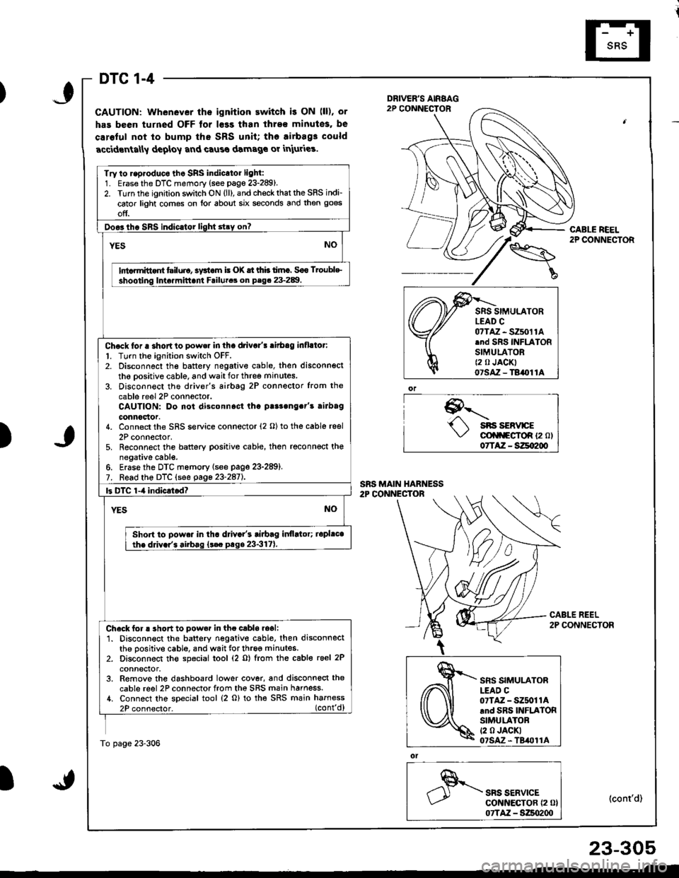
DTC 1-4
GAUTION: Whenever the ignition ewitch i! ON (ll), or
has been turned OFF tor l€ss than ihre€ minutes, be
caroful not to bump the SRS unit; tho airbag3 could
accidrnta[y deploy and caus€ damage or iniuries.
9--'-.- sns sERvrcE\,/ cli|f\FgfoR {2 ol07TAZ - SZqI200
ol
SRS SERVICEcot{ltEcToR {2 0}07TAZ - S:Zso2qt
CABLE REEL2P CONNECTOR
(cont'd)
Try to r.p.oduco tho SRS indicator light:1. Erase the DTC memory (see page 23-289).2. Turn the ignition switch ON (ll), and check that the SRS indi-
cator light comes on lor about six seconds and then goes
off.
Doo3tho SBS indic.tor light stry on?
YESNO
lnt rmittont tsiluio, systom i! (X tt thb timc. Soo Troublc
shooting Inte.mittani Failutca on P.g. 23-289.
Chock tor a shortto power in tha drivo/! ritbag inflllor:
l. Turn the ignition switch OFF.2. Disconnect the battery negativ€ cable, then disconnsct
th6 oositive cable, and wait for three minutes.
3. Disconn€ct the driver's airbtg 2P connector from the
cable reel 2P conn6ctor.CAUTION: Do not disconnost tha p!r3ong.t's rirbag
connoclor.4. Connect the SRS service connector (2 O) to the cable reel
2P connector,5. Reconnect the battery positive cable, then reconnect thenegative cabl€.6. Erase the DTC memory lsee page 23-289).7. Read the DTC (see gage 23-2aiL
|3 DTC 1-4 indicrtod?
YESNO
Shon to powa. in tha d val's tiabag itlflltor; iopl.cathe ddv.r'. airbag {t€c prge 23-317).
Check for ! short to pow.r in the cabls.oali1. Disconnect the battery negative cable. then disconnectthe positive cable, and wait for three minutes.2. Disconnect th€ special tool (2 o) from the cable reel 2P
conneclor.3. Remove the dashboard lower cover, and disconnect the
cable reel 2P connector from the SRS main harness./t. Connect the special tool (2 o) to tha SRS main harness
2P connector. (cont'd)
To page 23-306
)
,\fr)d
cffi
SRS SIMULATORLEAD C07TAZ - SZ5011Arnd SRS INFLATORSIMULATORt2 0 JACKI07SAz - TBil011A
23-305
Page 1361 of 1681
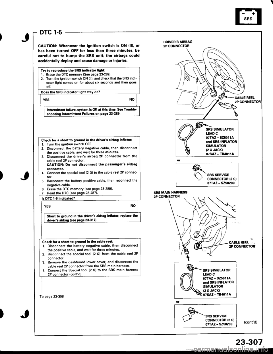
DTC 1-5
CAUTION: Whenever thc ignition switch i3 ON (lll, ot
has been turned OFF for less than throe minutss, bo
caretul not to bump the SRS unit; the airbsgs could
accidcntally deploy and cause damage or iniuri6.
DRIVER'S AIRBAG2P CONNECTOR
\"o""'"o'
CABI.E REEL
{cont'd}
)SRS SERVICECoNNECTOR 12 0)07TA2 - S250200
';
CABLEREEL.,2P OONNECTOF
)
ol
SRS SERVICECoNNECTOR (2 0l
07TAZ - SZSo2(xt
Try to ..produco the SRS indicator light:1. Erase the DTC memory (See page 23-289).2. Torn the ignition switch ON (ll), and chockrhattho SRS indi-cator light comes on for about six seconds and then goes
off.
Ooes ihe SRS indicator lighl slay on?
rffit
i .hooting ldt.rnittont Frilul.. on p.g. 23-289. I
Chock to. a 3hort to glound in tho drivor's airbag inflato.:
1. Turn the ignition switch OFF.2. Disconnect the battery nggative cable, then disconnect
the oositive cable, and wait forth.oe minutes.
3. Disconnect the driver's airbag 2P connoctor from the
cable reel 2P connector.CAUTION: Do not disconnsct tha pt!3onga]'t rirbrg
connoctor.4. Connect the special tool (2 0) to tho cable reel 2P connec_
tor,5. Reconnect tho battery positive cablo, then reconnoct the
negativ€ cable.6. Erase the DTC memory (see page 23-289)
7. Read the DTC (see pag623-2871.
k DTC 1-5 indicated?
YESNO
Sho.t to gtound in tha drive/s ri6ag infi.tor; ruplaco tho
drivor'3 .irbss (s.o p.g€ 23-3171.
Ch.ck tor a 3ho.t to gtound in tha cable ?ral:
1. Disconnect the battery negative cable. then disconnect
the oositive cable, and wait for three minutes.
2. oisconnect the special tool (2 0) lrom the cable reel 2P
connector,3. Remove the dashboard low€r cove., and disconnecl thg
cable reel 2P connector lrom the SRS main harn6ss,1. Connect the Special tool (2 0) to the SRS main harness
2P connoctor lcont'd).
To page 23-308
07TAZ - SZ50t1A.nd SRS INFLATORSIMULATOR{2 0 JACK}07SAZ - TB/OI lA
SRS SIMULATORLEAD C07TAZ - SZ501rAand SRS INFLATORSIMULATOR(2 0 JACKI07SM - TBi|t}l1A
23-307
Page 1372 of 1681
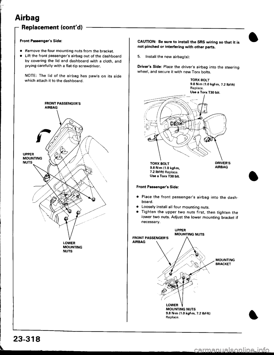
Airbag
Replacement (cont'd)
LOWERMOUNTINGNUTS
Fror|t P..s6nger'r Side:
. Remove the tour mounting nuts from the bracket.. Lift the front passenger's airbag out of the dashboard
by covering the lid and dashboard with a cloth. andprying carefully with a flat-tip screwdriver.
NOTE: The lid of the airbag has pawts on its sidewhich attach it to the dashboard.
CAUTION: Be sure to install the SRS wiring so that it isnot pincbed or interfering with other parts.
5. Install the new airbag(s):
Driver's Side: Place the driver's airbag into the steeringwheel. and secure it with new Torx bolts.
TORX BOLT9.8 N.m 11.0 kgf.m, 7.2 tbf.ft)
TORX BOLT9.8 N.m lt.o kgt m,7.2lbf,ftl Reptace.U36 a Torx T30 bit.
Front Paseenge/s Side:
Place the front passenger's airbag into the dash,bosrd.
Loosely install all four mounting nuts.Tighten the upper two nuts first, then tighten thelower two nuts. Adjust the lower mounting bracket ifnecessarv.
a
a
MOUNTING NUTS9.8 N.m (1.0 kgf.m. 7.2 lb{.ftlReplace.
Us€ a Torx T30 bit.
MOUNTING NUTS
Page 1376 of 1681
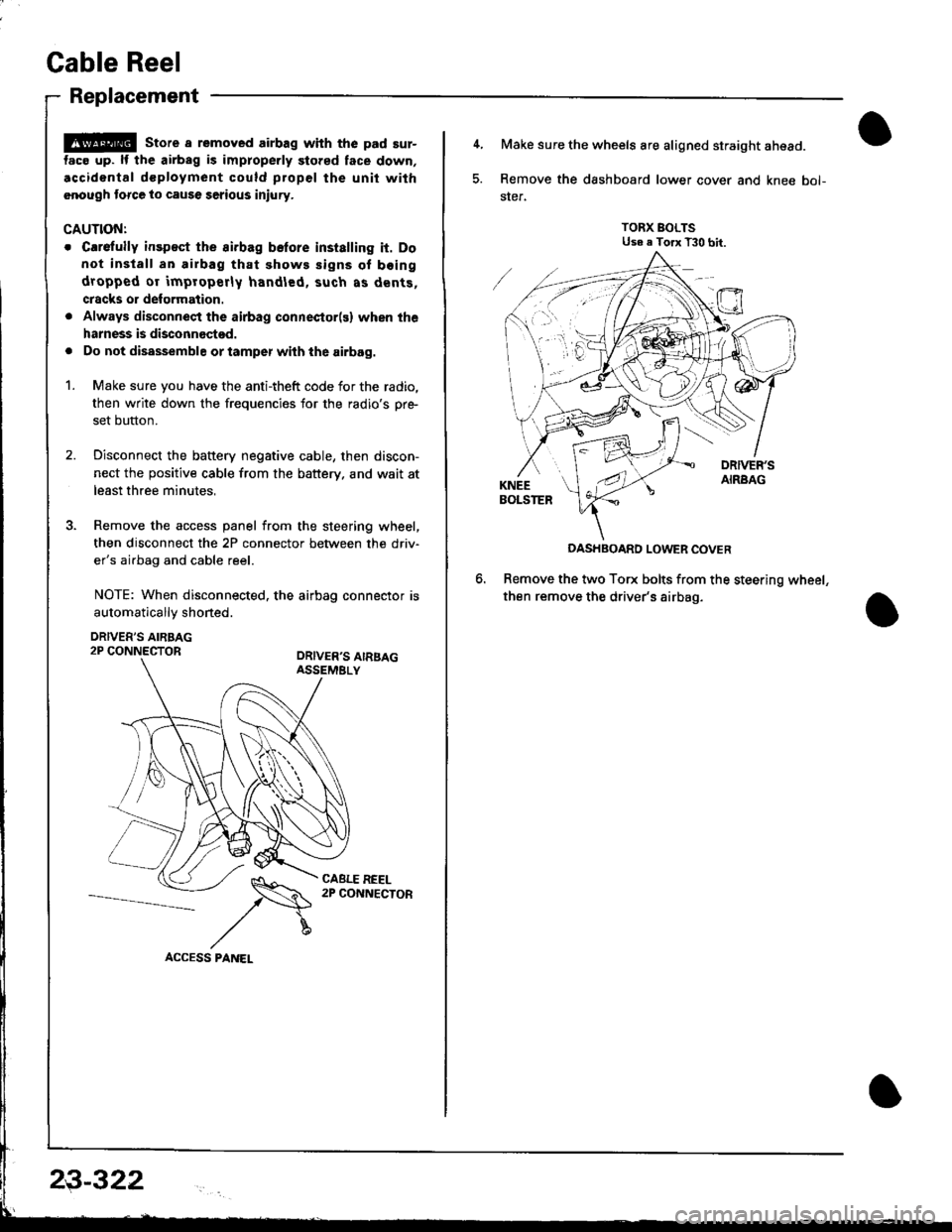
Cable Reel
Replacement
@ store a removed airbag with the pad sur-
tac€ up. lf the airbag is improperly stored face down,
.ccidontal dcployment could propel the unit with
.nough torce to cause serious injury.
CAUTIONT
o Carefully insp€ct the airbag belore installing it. Do
not install an airbag that shows signs of boing
dropped or improperly handled, such as dents,
cracks or deformation.
. Always disconnect the airbag connector(s) when the
harness is disconnectod.
. Do not disassemble or tamper wiih the airbag.
1. Make sure you have the anti-theft code for the radio,
then write down the frequencies for the radio's pr+
set button.
2. Disconnect the battery negative cable, then discon-
nect the positive cable from the battery. and wait at
least three minutes,
3. Remove the access panel from the steering wheel,
then disconnect the 2P connector between the driv'
er's airbag and cable reel.
NOTE: When disconnected. the airbag connector is
automaticallv shoned.
DRIVER'S AIRBAG2P CONNECTORORIVER'S AIRSAGASSEMELY
CABLE REEL2P CONNECTOR
23-322
4, Make sure the wheels are aligned straight ahead.
5. Remove the dashboard lower cover and knee bol-
ster.
TORX BOLTSUse e Torx T30 bit.
DASHBOARD LOWER COVER
Remove the two Torx bolts from the steering wheel,
then remove the driver's airbag.
Page 1379 of 1681
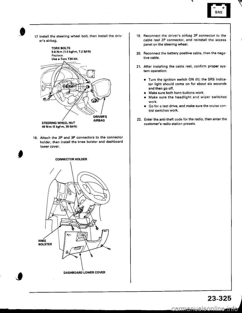
Instsll the steering wheel bolt, then install the driv-
er's airbag.
TORX BOLTS9.8 N m {1.0 kgf'm,7.2 lbtftlReplace.U3e . Torx T30 bit.
STEERING WHEEL NUT19 N.m (5 kgl.m, 36 lbl.ftl
Anach the 2P and 3P connectors to the connector
holder. then install the knee bolster and dashboard
lowgr cover,
le
CONNECTOR HOLDER
DASHBOARD LOWER COVER
23-325
\
'19. Reconnect the driver's aibag 2P connector to the
cable reel 2P connector, and reinstSll the access
panel on the steering wheel.
20, Reconnect the battery positive cable, then the nega-
tivs cable.
21. After installing the cable reel, confirm proper sys-
tgm operation:
Turn the ignition switch ON (ll); the SRS indica-
tor light should come on for about six seconds
and thsn go off.
Make surs both horn buttons work.
Make sure the headlight and wiper switches
Go {or a test drive, and make sure the cruise con-
trol switches work.
Ent6r the anti-theft code for tho radio, then enter the
customsr's radio station presets.
a
a
Page 1390 of 1681
Circuit ldentification for In'Line and Fuse Box Connectors
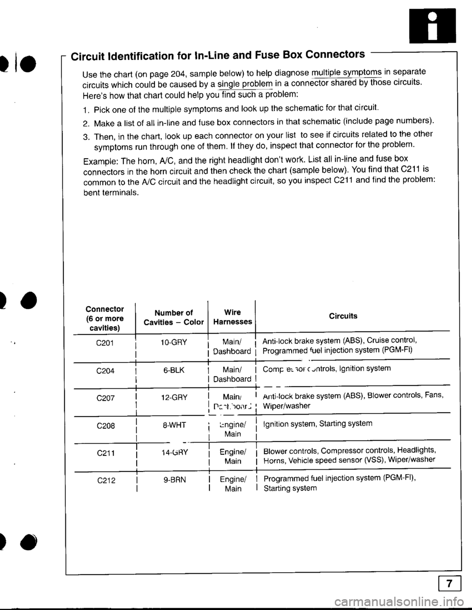
tuse the chart (on page 204, sample below) to help diagnose multiple symptoms in separate
circuits which could be caused by a single problem in a connect,oishared by those circuits'
Here's how that chart could help you find such a problem:
1. Pick one of the multiple symptoms and look up the schematic for that circuit'
2. Make a list of all in-lrne and fuse box connectors in that schematic (include page numbers).
3. Then, in the chart, look up each connector on your list to see if circuits related to the other
symptoms run through one of them. lf they do, inspect that connector for the problem.
Example: The horn, A,/C, and the right headlight don't work. List all in-line and fuse box
connectors in the horn circuit and then check the chart (sample below). You find that C211 is
common to the A,/C circuit and the headlight circuit, so you inspect c211 and find the problem:
bent terminals.
)Connector
(6 or more
cavities)
Numbel of
Cavities - Color
1O-GRY
I 12-GRY
I
Wire
Harnesses
I Main/ | ComP er 'ror c.ntrols,
I Dashboard I
Circuits
Ant!lock brake system (ABS), Cruise control,
Programmed {uel injection system (PGM-FD
!ngrnei
lvlain
lgnition system
Antilock brake system (ABS), BIower controls, Fans,
Wiper/washer
lgnition system, Starting system
Blower controls, Compressor controls, Headlights'
Horns, Vehicle speed sensor (VSS), Wiper/washer
Programmed fuel injection system (PGM-Fl)'
Starting system
Engine/ |Main I
)
Page 1400 of 1681
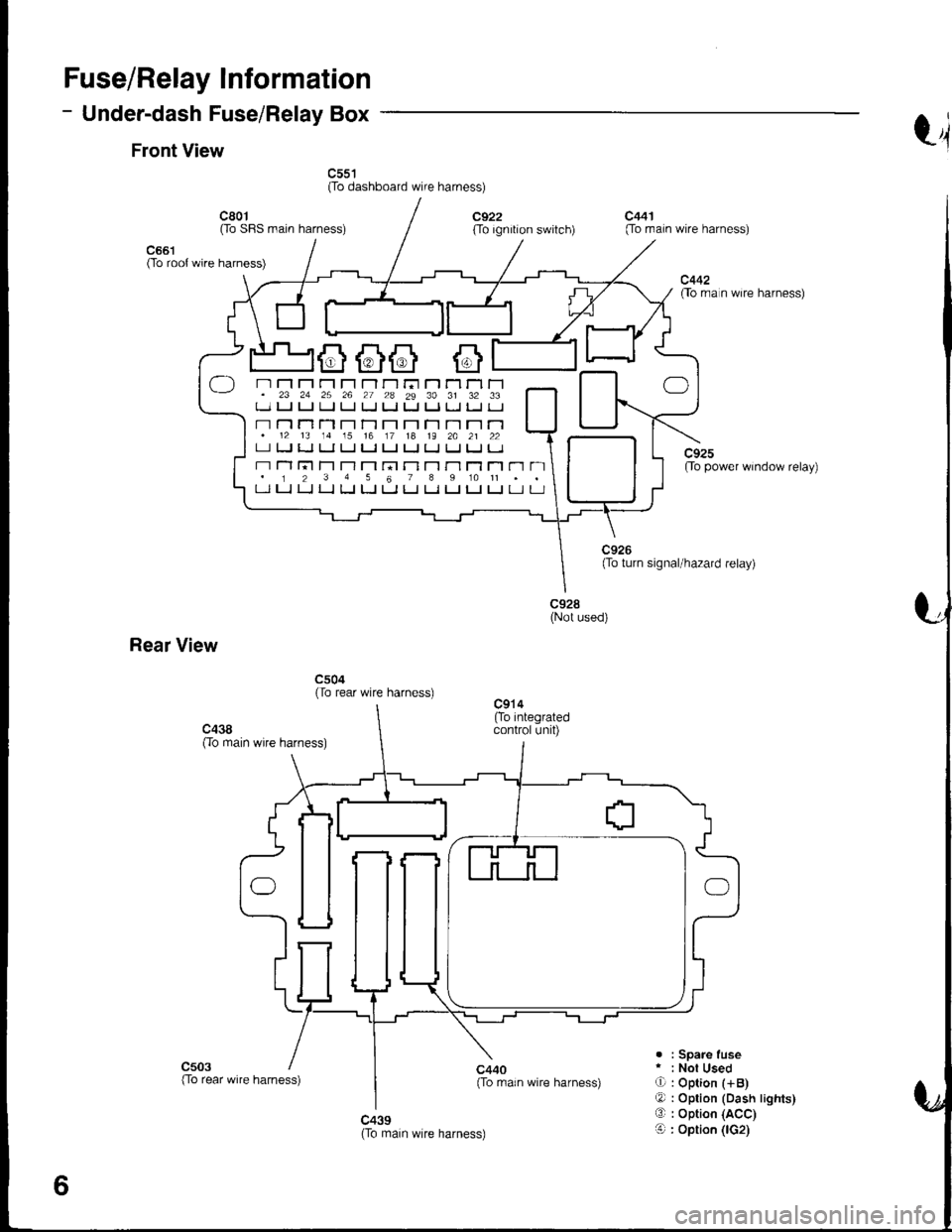
Fuse/Relay Information
- Under-dash Fuse/Relay Box
Front Viewt4
c55't(To dashboard wire harness)
c661(To root wire harness)
c801Oo SFIS main harness)c922(To ignition switch)
c440{To rrain wire harness)
c441(To main wire harness)
c442flo rra n wire harness)
c92sOo power window relay)
c928(Not used)
Rear View
c504(To rear wire harness)
c503. : Spare fuser : Not UsedO : Option (+B)
O : Option (Dash lights)O : Option (ACC)
O : Option (lG2)c439(To main wire harness)
6
-) n Fl r"r r'r rl r-l r-r ri r'1 Tl rl r-1. 23 24 25 26 27 2a 29 30 31 32 33t_-.1 u u ! tJ LJ Ll t. Ll tJ l. tJ
- r-l n T'l T-l r't T-1 T-t r-l T-t r-l r'1.12 13 14 15 16 17 18 19 2A 21 22LI tJ LJ LI tJ I.J t-J tJ IJ IJ IJ I.J
r-r Tl l;t T'l T-l T'1 rn r-l T-t r'l T1 Tl r'1 n. 1 2 3 4 5 6 7 I 9 10 11 . .t-l LJ LJ LJ LJ [J t-t LJ Ll LJ t_l t-J Lr u
(To rear wire harness)