Page 1181 of 1681
auge Assembly
Circuit Diagram (cont'dl
iG
BLK,IYEL
No.5 (10A)
V
IREO/GRN
I e,s
TURN SIGNALSWITCN
v--=v
tltl
tlGBN/BLIJ GRN,YEL
lltl
I e's I s,o
"i.uv"'T""
H^,J.**.GBN . INTEGRATEO
I coNrRor uNrT
,'T--l ffi--l
lI*ni lI*i
il i*i t i
i. li;, I
L__ i L:'�_" i(Hatchback) (Sedan)
| 012
GRNORN
vECM
louBLK
G20lG401
RIGNTTURNSIGNALINDICATORL]GHT(1.4w)
TAILGATE.OPENINDICATORLIGHT(1.4!9
RED/BLU GBN/RED| | . ABS CoN-FOL U\lTI .NTEGFATED I .INTEGBATED
|
*v^"
|
-'v*
| .roL-" I or*frro
ts Fo.''-,,-jBED/BLU GRN/RED GHNi RED
rrl
AAA
Yu'**- Y*,,r" Y**
l3$i;.?.'' 13ffi3- ll#,
| | l!i,Iib'.
TIT:-_:
GXXX G3O1
23-124
Page 1194 of 1681

t
{)
)
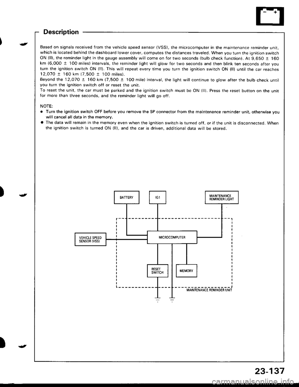
Based on signals received from the vehicle speed sensor (VSS). the microcomputer in the maintenance reminder unit,which is located behind the dashboard lower cover, computes the distances traveled. When you turn the ignition switchON (ll), the reminder light in the gauge assembly will come on for two seconds (bulb check tunction). At 9,650 1 160km {6,000 1 1O0 miles} intervals, the reminder light will glow for two seconds and then blink ten seconds after you
turn the ignition switch ON (ll). This will repeat every rime you turn the ignition switch ON {ll) until rhe car reaches12,O7O ! 1 60 km (7,500 t 100 miles).
Beyond the 12.o1O ! 160 km (7,5OO t IOO mile) interval, the light will continue to glow after the bulb check untilyou turn the ignition switch otf or reset the unit.
To reset the unit, the car must be parked and the ignition switch must be ON (ll). Press the reset button on the unitfor more than three seconds, and the reminder light will go off.
NOTE:
. Turn the ignition switch OFF before you remove the 5P connector from the maintenance reminder unit, otherwise vouwiil cancel all data in the memory.
a The data will remain in the memory even when the ignition switch is turned off, or if the unit is disconnected. Whenthe ignition switch is turned ON (lll, and the car is driven, additional data will be stored.
{
23-137
Page 1223 of 1681
Lighting System
Combination Light/Turn Signal Switch Test
Remove the dashboard lower cover and steering
column covers {see page 23-721.
Disconnect the 4P and 7P connectors from the
switch.
Check the connector and socket terminals to be sure
they are all making good contact. lf the terminals are
bent, loose, or corroded, repair them as necessary,
and recheck the system.
Check lor continuity between the termanals in each
switch position according to the table.
B
D
E
H
4P CONNECTOR
7P CONNECTOR
23-166
Page 1230 of 1681
)
I
Front Parking/Front Turn
Signal Lights
Replacement
'1.Remove the screw, and pull the front parking/tront
turn signal lights out of the front bumper.
CONNECTOR
l.
FRONT TURN SIGNAL LIGHT
Disconnect the 3P and 2P connectors trom the
lights.
Turn the bulb socket 45o counterclockwise to re-
move it from the housing.
/e*----
Ar)
fl
Front Side Marker
Lights
1.Remove the screw, and pull the tront side marker
light assembly out of the tront bumper.
Disconnect the 3P and 2P connectors from the
lights.
Turn the bulb socket 45o countefclockwise to re-
move it from the housing.
FRONT SIDE MARKER LIGHT
Replacement
23-173
Page 1231 of 1681
Taillights (Hatchback)
Replacement
1.
2.
Open the rear hatch.
Remove the rear panel lining and the side lining (see
section 20).
Disconnect the 5P connector from the taillight.
Remove the six mounting nuts, then pull out the
taillight.
NOTE:
a lnspect the gasket. Replace it if it is distorted or
stays compressed.
a After installation, run water over the lights to
make sure they don't leak.
6P CONNECTOR
Replacement
Rear turn signal/Rear parking lighis.
1 . Open the rear hatch, then remove the access panel.
2. Remove the bulb from the bulb socket.
O: REAR TURN SIGNAL LIGHT BULB (32 CP)
@: REAR PARKING LIGHT BULB {3 CP)
Brake/Taillighr/Back-up lights:
1. Open the rear hatch.
2. Remove the rear panel lining {see section 20).
(i): BACK-UP LIGHT BULB (32 CF,
(Dr BRAKE/TAILLIGHT BULB (32/3 CP)
ACCESS PANEL
23-174
----
Page 1233 of 1681
Taillights (Sedanl
Bulb Replacement
Taillight:'1. Open the trunk lid, then remove the rear panel lin-
ing and side lining (see section 20).
2. Remove the bulb from the bulb socket.
O: BRAKE/TAILLIGHT BULB 132/3 CPI
@; TURN SIGNAL LIGHT BULB (32 CP)
@: REAR PARKING LIGHT EULB (3 CP)
23-176
Inn€r Taillight:'1. Open the trunk lid, then remove the bulb housing,
2. Remove the bulb from the bulb housing.
BACK.UP LIGHT BULB (32 CP}
BRAKE/TAILLIGHT BULB {32l3 CP)
O:
/n.
EULB HOUSING
Page 1249 of 1681
Side Marker/Turn Signal/Hazard Flasher System
Component Location
TURf{ SIGNAL INDICATOF LIGHYS(ln the gaugo assembly)Eulb Locations, page 23-122
COMBNANON LIGHT SWTTCHReplacement. page 23-168Test, page 23-166
FUS€/RELAY BOX
HAZARD WARNING SWITCHReplacement, pago 23-195Test, pag€ 23-195
il
r-.1uuij tjt +ffi-------r--- _ ntll----------rn LJJ u
?UBN SIGNAL/HAZARD RELAYInput Test, page 23-'194
I
23-192
Page 1251 of 1681

Side Marker/Turn Signal/Hazard Flasher System
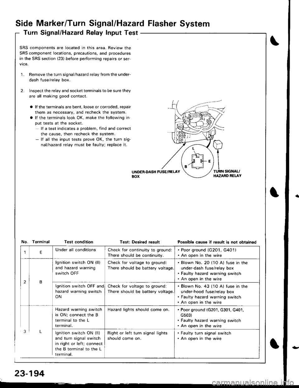
Turn Signal/Hazatd Relay Input Test
\
t
SRS components are located in this area. Review the
SRS component locations, precautions, and procedures
in the SRS section (23) before performing repairs or ser-
1.Remove the turn signal/hazard relay from the under-
dash fuse/relay box.
Inspect the relay and socket terminals to be sure they
are all making good contact.
a lf the terminals are bent, loose or corroded, repair
them as necessary, and recheck the system.
a lf the terminals look OK, make the tollowing in
put tests at the socket.
lf a test indicates a problem, find and correct
the cause, then recheck the system.- lf all the input tests prove OK, the turn sig-
nallhazad relay must be faulty; replace jt.
2.
UiTDER.DASH FUSE/RELAYaox
TURN SIGNAL/HAZAND RELAY
No. Telminal Test conditionTest: Deaired resultPossible cause it result is not obtained
lgnition switch ON (ll)
and turn signal switch
in right or left; connect
the B terminal to the L
rermtnat,
Check for continuity to ground:
There should be continuity.
. Poor ground (G201, G401). An open in the wire
lgnition switch ON (ll)
and hazard warning
switch OFF
Check for voltage to ground:
There should be battery voltage
. Blown No. 20 ( 10 A) fuse in the
under-dash fuse/relay box. Faulty hazard warning switch. An open in the wire
lgnition switch OFF and
hazard warning switch
ON
Check lor voltage to ground:
There should be battery voltage.
. Blown No. 43 ('1 0 A) f use in the
under-hood fuse/relay box. Faulty hazard warning switch. An open in the wire
Hazard warning switch
is ON; connect the B
terminal to the L
rermtnat.
Hazard lights should come on.. Poor ground (G201, G301, G401,
cs03). Faulty hazard warning switch. An open in the wire
Right or left turn signal lights
should come on.
. Faulty turn signal switch. An open in the wire