Page 1426 of 1681

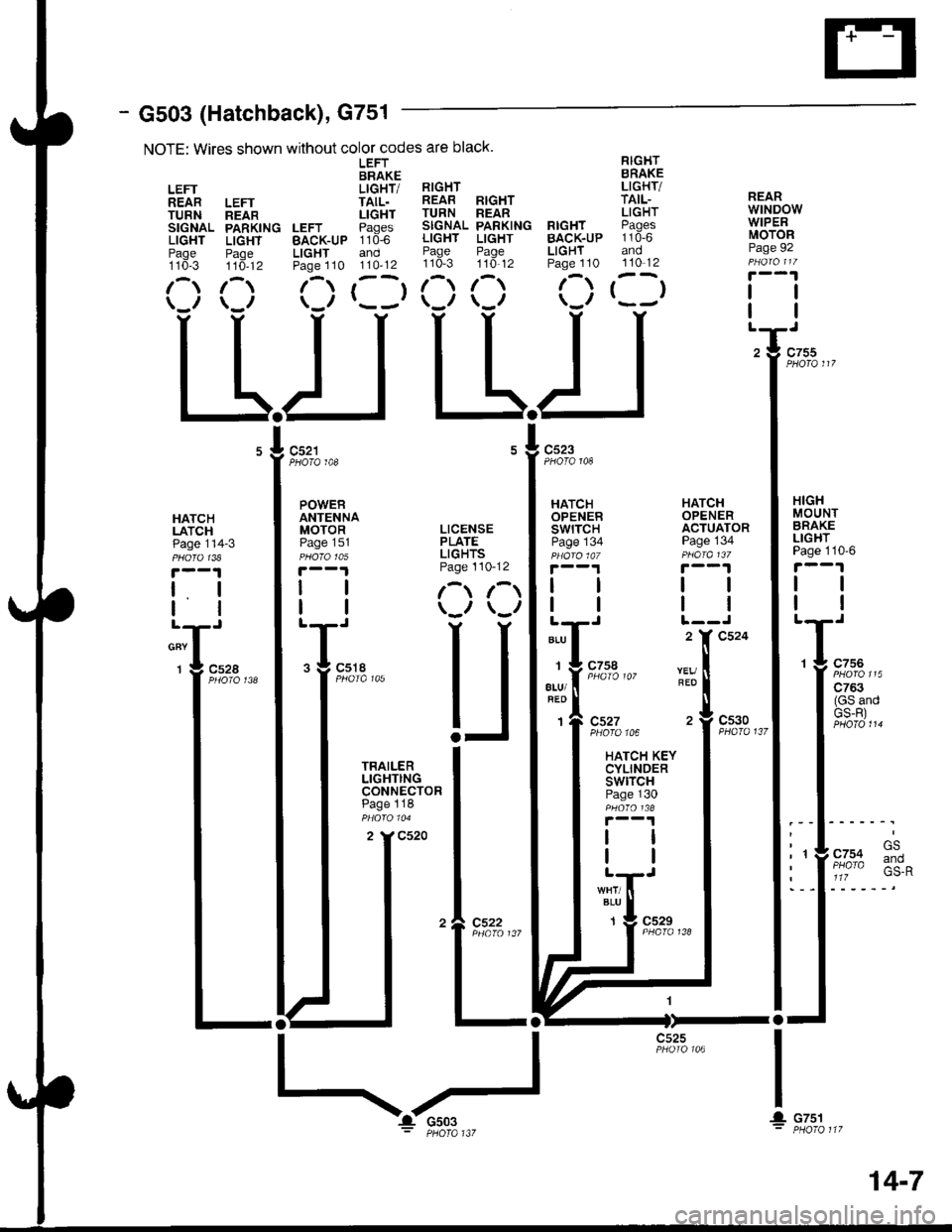
- G503 (Hatchback), G751
NOTE: Wires shown without color codes are black.
LEFT RIGHTBRAKE BRAKE
LEFT LIGHT/ RIGHT LIGHT/
REAR LEFT TAIL. REAB RIGHT TAIL-
TURN neln LIGHT TURN REAR LIGHT
SIGNAL PARKING LEFT Paqes SIGNAL PARKING RIGHT PAgCS
LIGHT LIGHT BAcK-uP 110-6 LIGHT LIGHT BACK.UP 110-6
Paqe Paoe LIGHT and Page Page LIGHT andtto*-s ttd-tz Paoe 110 110'12 110-3 110'12 Page 110 110-12
1-) 1- (-) r--r 1- 1-) f-) t--t(_r \_r \-/ r---' \-,, \-,, \.'/
LLIJ L-L.I
REARwtNDowWIPERMOTORPage 92
tl
PHOTO 108PHOTO 148
HATCHLATCHPage 114-3
t. I
lltl
cnv I
1 g c52a
HATCHOPENERSWITCHPage 134
HATCHOPENERACTUATORPage 134
HIGHMOUNTBRAKELIGHTPage 110'6
tl
tl
1 g c756
| ':::2"'
I (GS andI GS-R)
.l .rl' t- GS
: 'YF/o% :*^I a 1lz
I
IL
ALU
1
atu/
1
REO
c527PHOfO 106
HATCH KEYCYLINDERswtrcHPage 130
c530PHA|O 137
BLU
1c529
I
! cTsl
c525
POWERANTENNAMOTOR LICENSEPaoe 151 PLATEpu6rctos LIGHTS
|.--1 Page 110-12
| | l-t r-t
I | \-., \-,,
T;,. U
I iHi'$t"" I
I :3:.:ll: I
I ^ -:-"^ I
tt*l
tll
I I
'�l e:3?.,,,
ltl-ll-
14-7
Page 1427 of 1681
Ground Distributioh (cont'd)
- G503 (Sedan)
NOTE: Wkes shown without color codes are black.
LEFTIN NERBRAKELEFT LIGHT/BACK-UP TAILLIGHTLIGHT Paqes 110-7Paqe 110,1 and 110-13
r-,r ,--r\_,, r- -,
c534
L.JLIJL.J
TRAILERLIGHTINGCONNECTORPage 118
RIGHTINNERBRAKELIGHT/TAILLIGHTPages 110-7and 110-13
()
RrcHr l!-c.{r !'rqlt-
!iTfi^. iff#"" iilt[i",
b:::1,0. ii3:3 :i3::lts'
(:) (:) rllr
TRUNKLATCHswtTcHPage 114-3
tl
tl
2 Y C535
RIGHTBACK-UPLIGHTPage 110 1
/\
LEFTREARTURNSIGNALLIGHTPage 110-5
LEFTREARPARKINGLIGHTPage110-13
/\
LEFTOUTERBRAKELIGHT/TAILLIGHTPages 1'10-7and 110-13
()
'98-'�99
Model
(Notuseo)
cs22
HIGHMOUNTBRAKELIGHTPage 110-7
tl
REARwrNDowDEFOGGERPage 64
ll
14-8
Page 1457 of 1681

Cruise Control (cont'd)
- How the Circuit Works
The cruise control system uses mechanical and
electrical devices to maintain the car's soeed at a
setting selected by the driver.
System Description
The cruise control unit receives command signals
from the cruise control main switch and the cruise
control SevBesume switch. With the ignition switch
in ON (ll) or START (lll), voltage is provided to the
cruise control main switch. When you push the
switch to on, power is provided to the cruise control
unit and the brake switch.
The cruise control unit receives information about
operating conditions from the brake switch, the
ignition control module (lCM), the vehicle speed
sensor (VSS), and the clutch switch (manual
transmission) or the A,/T gear positton switch
(automatic transmission). The cruise control unit
then sends signals to the cruise conirol actuator
which regulates the throttle position to maintain the
selected speed. The control unit compares the
aclual speed of the car to the selected speed. The
control unit then uses the result of that comoarison
to oDen or close the throttle.
The brake switch releases the system's control of
the throttle at the instant you press on the brakepedal. The switch sends a signal to the control unit
by removing power from the normally closed brake
input (GRY wire), and providing power at the
normally open brake input (GRNMHT wire). The
control unit responds by allowing the throttle to
close. The clutch switch or the A/T gear position
switch sends a "disengage" signal to the control unit
that also allows the throttle to close.
The cruise control system will set and automatically
maintain any speed above 25 mph (40 km/h). To set
it, make sure the main switch is on and the switch
indicator is on. Then, after reaching the desired
speed, press the set switch. This sends a "set"
signal to the cruise control unit which, in turn,
controls the cruise control actuator to maintain the
set soeed.
When you push the SET switch and the cruise
control system is on, the "cruise control" ON
indicator lights up.
34-4
You can cancel the cruise control system by
turning the main switch off. This removes power to
the control unit and erases the set sDeed from
memory. lf the system is disengaged temporarily
by the brake switch, or clutch switch, and the car's
speed is still above 25 mph, press the RESUME
switch: the car will automatically return to the
previously set speed.
For gradual acceleration without pressing the
accelerator pedal, push the RESUME switch and
hold it there. This will send an "acceleration" signal
to the control unit. When you release the switch, the
system will be reprogrammed tor the new speed. To
slow the car down, push the SET switch in and hold
it there. This sends a "deceleration" signal to the
control unit, causing the car to coast. When the
desired speed is reached, release the SET switch.
This reprograms the system for the new speed.
Reter to the Service Manual (Section 23, Electrical)
for specific tests or troubleshooting procedures.
Page 1497 of 1681
Indicators (cont'd)
@
tt
t(
tt
lt
tl
"-T
!T
!I
gI
IUNDER.HOODFUSE/RELAYBOX
UNDER-DASHFUSE/RELAYBOX
l-J-rr-trr1---l
LJi!*''i
DASHFUSE/RELAYBOX
FUSE s3NAZAAD104
18
BLl(YEL
11
811r
See PowerDistrabution,page 10-9.
See Turn Signal andHazard Warning Lights
SeeHeadlights
V
tlneoi IGRN tI._ I':r__
I
{
I
812
(NorUsod)
___l'd",,,
RIGHTTURNSIGNALINDICATORLIGHT
H
AASINOICATORUGHT
@
(usA)
@(Canada)
"..,::,f
t*'
! ,"" ro*o
il
;:i:it''l
see ABs
"r""." I "., "." trt
, !-------a.1, "uu, ott?fl%tf
sRsINDICATORLIGHT
m
XIGHBEAM'NDICATORLIGHT
E
FUSE 15ALTEANATORsP sEl{son.54
---t Diskibution, :
-rr"t:t--i'C5s1
Page 1507 of 1681

Wiperffasher (contd)
- How the Circuit Works
When the ignition switch is in ON (ll) or START (lll),
battery voltage is applied to lhe windshield
wiper/washer switch, and the windshield wiper
motor.
Low Speed
When you turn the wiper switch to LO, the wiper
motor's low speed winding is grounded through the
BLU wire and the LO speed contacts of the wiper
switch at G401, and the wipers run at low speed.
ParUOfi
When you turn the wiper switch OFF, the integrated
control unit (PARK input) grounds the wiper motor
through the BLUMHT wire. The cam switch on the
motor signals the integrated control unit that the
wipers are in the PARK position; the control unit
then removes ground from the motor, and the
wipers stop in the PARK position.
High Speed
When the wiper switch is in Hl, the high speed
windings ol the windshield wiper motor are
grounded through the BLUI/EL wire and the Hl
contacts of the wiper switch at G401 , and the
wipers run at high speed.
Intermittent
When the wiper switch is in lNT, battery voltage is
applied through the YEUBLU wire to the integrated
control unit (lntermittent wiper ON input). The
integrated control unit (lntermittenvPark Wiper
Control) grounds the low speed windings of the
wiper motor and the wipers make a single sweep
every few seconds (See Low Speed above). When
the wiper returns to the PARK position, the park
switch applies battery voltage through the
BLUMHT wire to the integrated control unit (PARK
input), and the wipers stop in the PARK position.
91-2
Mist
When you pull the wiper switch down to MIST
position, the high speed windings of the wiper motor
are grounded through the BLU//EL wire and the
closed contacts of the mist switch at G401, and the
wipers make one pass across the windshield at high
speed. The PABKOFF tunction then takes over and
the wrpers stop in the PARK position.
Washer
When you pull the wiper switch toward you to turn on
the washer switch, battery voltage is applied to the
washer motor. The motor pumps fluid onto the
windshield until you release the lever. On models
with combined wiper/washer operation (Canada), the
integrated control unit (windshield washer ON input)
senses power al the BLI(GRN wire terminal and
runs the washer motor whenever the wioers run.
Reter to the Service irlanual (Section 23, Electrical)
for specific tests or troubleshooting procedures.
Page 1511 of 1681
Headlight Switch (cont'd)
-.I UNDER.OASH
From B onpr€vious page.
FUSE/RELAYBOX
't8
2 |' C319
c302
LEFTFRONTSIDEMARKERLIGHTPage 110-11
3 l' C320
LEFT FRONTPARKING/TURNSIGNAL LIGHTPage 1 10-11
RIGHTFRONTSIDEMARKERLIGHTPage 1 10- l1
RIGHT FRONTPARKING/TURNSIGNAL LIGHTPage 110-11
100-2
Page 1515 of 1681
Turn Signal and Hazard Warning Lights
From A onrnts page.
v
i"""*i'.!,
F;%,,r
f'T----.lUNDER-
I r FUSE 12 | DASH
i )t8I"'**. i5Eii{,LIL----JBOX
r
I
I
-f,
)I
I"3Y(
- Hatchback
FUSE 53}IAZABO10t
c452
'tl Y C551
.I UNDER.
I HOOD
: FUSE/I RELAYJ BOx
See PowerDistribution,page 10-9.
UNDER-DASHFUSE/RELAYBOX
HAZARDWARNINGSWITCH
11(RS 10)
See Ground Distribution,page 14-5.
WHT/GRN
WHT/GRN
WHT/GNN
See Dash andConsole Lights
TRED/BrK
I
--U cssg
See GroundDistribution,page 14-5.
"l^f :,*+:..
Orrr<
*^ l/r--<
-r- 91q1--GBN/OBN
1
GAUGEASSEMBLY
---";;il-::r "*.
!F[ ,**t,**
pase. t
-----11I csoo
@i{FH'"'
----"-""-".i]ffi;---
! Ell cnn '
IV:=..=--l 'G
.,g l_______----.----,,1F
LEFT TUFN
rA I'l3i$'o'
\f,/t LIGHr
see Y fHGauges, I I
-lInorcarors >------+-
RIGHT TURNSIGNALI}IDICATORUGHT
ToAonrnrs page_
* = '98-'99 l,4odels
HAZARDWARNII{GswtTcHLIGHT
110-2
Page 1516 of 1681
c434
>-ra
BLK
COMBINATIONLIGHTswtTcHl!rnSignalSwllch
L-
From B onfacing page.
v
iGRN/BLU I GFN/BLU
. Jl "",%%* u
'T
"r""* I
______e-t
"ih::-i'
I
I
t6
GFN/BLU
GFN/BLt'
1
H
I::
[ff
c320
ALK
A
c504
Used) 15
GRN/EIU
CRN/ALU
SeeParkingLights cFN/BLU
3
---.I UNDER-DASHI FUSE/RELAY
iF,oJ","
c504 10PhoTa 62
GFN/YELo"nrtaa
I
----+
GBN/BLU ;T:]* I
c516(ln-line connector;may not be presentin all cars.)
a
[,*
RED/BLK See
,[r",...'---
/-l'_' LEFT FBONTT lo q T PARKING/TURN
\:9./ srcNAL LrcHr
BLK
See GroundDistribution,page 1+3.
Y
T
/A lerr neanI b I TURN SIGNAL
v/ LIGHT
Y
"t"
I see croundOr-( Dist.ibution,
rA\+,1?il'qEll r ,'/ LrGHr
*"r
/-m BtcHT FRONTrlo <2{ I PARKING/TURN
\:-S-,/ srcNAL LlcHr
c203
BLK-
See GroundDistribtdion,page 14-2.
I
L__J'+: G201
BLK
c523
L-_J+.= G30t
From C ontacrng Page.
v
tGFNffEL I
9:"4,2," t Jl "",u"%*
110-3