1998 HONDA INTEGRA turn signal
[x] Cancel search: turn signalPage 1517 of 1681
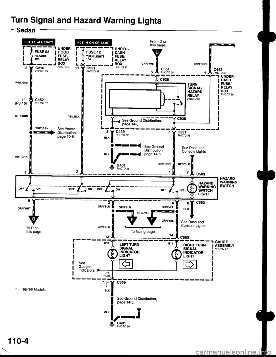
Turn Signal and Hazard Warning Lights
From D onthis page.
v
i"""*l'.!,
F,*%.,r
- Sedan
11 Y C551GRN/OFN
4
rT----'l UNDER.I I FUSE 12 | DASH
i ) TH"uo"'. i[EiE{,L j.___-J BOXc216
c452
WHT/GRN
TURNSIGNAUHAZANDRELAY
UNOER.DASHFUSE/RELAYBOX
HAZARDWARNINGswtTcH
11(BS 10)
See Ground Distribution,page 1+5.
YEUBLK
See PowerDistribution,page 1G9.
r andLights
' c551
Ser
BED/8
i5't)IQ 5A
See Dash aConsole LiC
Ioret.x ll
lt.-1 c:
BED/8LK
7
GFX/OBN
'|
See GroundDishibltion,page 1+5.
"l-1m*"
arrr<
*.L_;,,-'
---";;|tr--sf cs63
F[ ***,,,*
page i
.-----11I cr"o
RIGHT TURN
@ffiH*
IH
----";";.i-tr-;;--
! Elt o"n '
lv:;..=--j
-G
rs l_______-------:-'1F
LEFT TURN
@il!H'*
3:",n"", i|€]Indicators )--_-_-{___
-"-u
ToDonrnrs page.
GAUGEASSEMBLY
* = 98-'99 l\4odels
HAZANOWARNINliswtTcHUGHT
110-4
Page 1523 of 1681
Headlights (cont'd)
- How the Circuit Works
Low Beam OperationRefer to the Service Manual (Section 23, Electrical)
for specific tests or troubleshooting procedures.
With the headlight switch in HEAD and the dimmer
switch in LO, current flows through the headlight
switch, fuse 21 , tuse 22, and the low beam
filaments to ground, and the low beams come on.
tligh Beam Operation
With the headlight switch in HEAD and the dimmer
switch in Hl, current flows through the headlight
switch, dimmer/passing switch, fuses 4, 5, 21, and
22, and the low and high beam filaments to ground,
and the low and high beams come on.
Current also tlows through the high beam indicator
light to ground. The high beam indicator comes on
to remind the driver that the high beams are on.
Flash operation
The flash feature works with the headlight switch in
OFF, PARK, or HEAD (low beams). When you
move the flash-to-pass switch to ON, current flows
through the switch, fuses 4 and 5, and the high
beam filaments to ground, and the high beams
flash. The high beam indicator also flashes during
the flash oDeration. The flash function has no effect
it the high beams are already on.
Daytime Running Lights Day Operation
When you turn the ignition to ON (ll) with the
parking brake released, the daytime running lights
control unit supplies battery voltage at the
WHT/RED wire. This voltage is applied to the high
beam headlights through the daytime running lights
resistor. Each high beam headlight receives less
than battery voltage causing them to come on al
reduced brightness.
lf the parking brake is set, a ground signal is applied
to the daytime running lights control unit at the
RED/GRN wire. It the parking brake is set when you
first turn the ignition switch to ON (ll), the high beam
headlights will remain off until you release the
parking brake. Once the high beam headlights are
in day mode, setting the parking brake will not
cause the headlights to turn off . When low or high
beam operation is requested, baftery voltage trom
the headlight switch is applied to the daytime
running light control unit via the RED/vVHT wire.
The daytime running light control unit then
discontinues the daytime running light mode.
1 10-10
Page 1524 of 1681
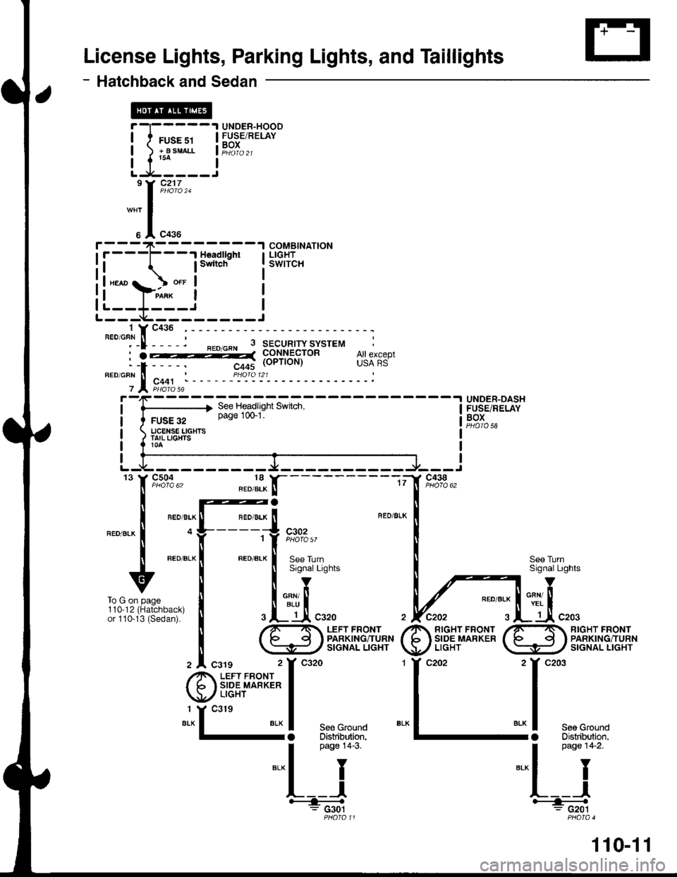
License Lights, Parking Lights, and Taillights
- Hatchback and Sedan
UNOEB-HOODFUSE/RELAYBOX
COMBINATIONLIGHTSWITCH
UNDER-OASHFUSE/RELAYBOXPHOTO 58
RED/gLK
I
@il*+'m;
c438
f, n%"' "."f-tr'-----
| @a
I "'. -, " tl "'. ., " i BED/il ---'l --'r
I o y_____ii ,%%,,
t ".o ".* | ".o ".* ! a"" ,r,nlt ---- tl ----t :]
u ! ls'snarlishts
,irr*^ . I inl
i3?iH;ll' I .l- tAcszo
il ^/r'- . LEFr FRONr
i \s#/3m,rlti#'#
z |. csrg 2Y ca2o
@i"fft**t-;
"*13!
***
I
Pase 14-3
=-l I
L__l__=;*;
See TurnSignal Lights
env ltYEL I
_ Jl c203110,12or 110-RIGHT FRONTPARKING/TURNSIGNAL LIGHT
il-,;;-l
Llr_i,193;]"*
"*r I
u I "o.u
i.--+-----.-r""*r;-l
il lswitch Ill"*or o.t I
!|"*"};^i_*'i I
rl__r_ _i IL--- i---------J
To G on page
110-11
Page 1533 of 1681
![HONDA INTEGRA 1998 4.G Workshop Manual i-1:
!._ll
""*"t-[:
::il
--1 UNDER- TT----1 UNDER-DASHsE s3 I HOOD I f FUSE 12 | FUSE/RELAY^Bo
|FE:F{, i },8In""" iF"?T".,__.1 BOX U-:L-----r
]3," f, rt,i%., FromAon
te Power t
tnrs Pase
:i:it8: HONDA INTEGRA 1998 4.G Workshop Manual i-1:
!._ll
""*"t-[:
::il
--1 UNDER- TT----1 UNDER-DASHsE s3 I HOOD I f FUSE 12 | FUSE/RELAY^Bo
|FE:F{, i },8In""" iF"?T".,__.1 BOX U-:L-----r
]3," f, rt,i%., FromAon
te Power t
tnrs Pase
:i:it8:](/manual-img/13/6069/w960_6069-1532.png)
i-1:
!._ll
""*"t-[:
::il
--1 UNDER- TT----1 UNDER-DASHsE s3 I HOOD I f FUSE 12 | FUSE/RELAY^Bo
|FE:F{, i },'8In'""'" iF"?T".,__.1 BOX U-:L-----r
]3," f, rt,i%., FromAon
te Power t
tnrs Pase
:i:it8: vere'�xl Y
I ..[
- - - - - - rJ.- - - - --"]:l-tr "*.
FIOM E ONrnrs page.
v
ll cougrlrrrolcRNioFN I LTGHT
, Jl "o.o P#["'i]
HAZARDWARNINGswtTcH
See Dashand Console
'YL
TumSignalSwitch
c55tPHaro 5a 6
c434
c442
.t UNDER-i DASH
1
#
:*J
,t.T;
o4
r:I
:[- T
illso*"'�" ""_r",1
.N_'--------f"
FUSE/FELAYBOXTURNSIG}IAUHAZABDRELAYPHO|O @
I
t;;.---+
"YF,o9:",,'f,9"%:1., 4Y9,4:,2o*15
".* | cnr'onr I entt onr I cFN BLU
!--.itrr"q1fi V Vo""".,
I naoe l+-s ro i on To B on
".- I I
this Pase tn't o"n"
o"n ".,
yi,;"
HAZANOWANTINGswtTcHLrcHT ori
c926
ll;t
118-1
Page 1602 of 1681
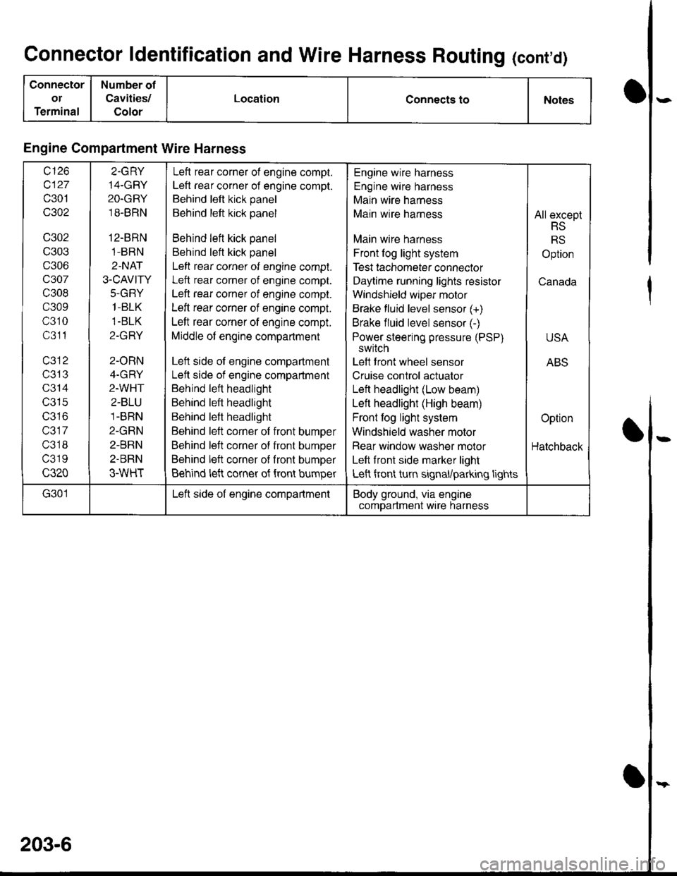
Connector ldentification and Wire Harness Routing (cont'd)
Connector
or
Terminal
Number of
Cavities/
Color
LocationConnects toNotes
Engine Compartment Wire Harness
wt10
c127
c301
c302
c302
c303
c306
c307
c308
c309
c310
c311
T/JIJ
c314
c315
IJJ IO
c317
c318
c319
c320
2.GRY
14-GBY
2O-GRY
18-BRN
12-BRN
1-BRN
2.NAT
3.CAVITY
J-(l|-I Y
1-BLK
1-BLK
Z-IfFI T
2-ORN
4-GRY
2-WHT
2-BLU
1-BRN
2-GRN
2-BRN
2-BRN
3-WHT
Left rear corner of engine compt.
Left rear corner of engine compt.
Behind left kick panel
Behind left kick panel
Behind left kick panel
Behind left kick panel
Left rear corner of engine compt.
Left rear corner of engine compt.
Left rear corner of engine compt.
Left rear corner of engine compt.
Left rear corner of engine compt.
Middle of engine compartment
Left side of engine compartment
Lett side of engine compartment
Behind left headlight
Behind left headlight
Behind left headlight
Behind left corner of front bumper
Behind left corner of front bumper
Behind left corner of fronl bumper
Behind left corner of {ront bumper
Engine wire harness
Engine wire harness
Main wire harness
Main wire harness
Main wire harness
Front log light system
Test tachometer connector
Daytime running lights resistor
Windshield wlper motor
Brake fluid level sensor (+)
Brake fluid level sensor (-)
Power steering pressure (PSP)
switch
Left front wheel sensor
Cruise control actuator
Left headlight (Low beam)
Left headlight (High beam)
Front fog light system
Windshield washer motor
Rear window washer molor
Left front side marker light
Left front turn signal/parking lights
All except
RS
RS
Option
Canada
USA
ABS
Option
Hatchback
G301Left side of engine compartmentBody ground, via engine
comDartment wire harness
203-6
Page 1604 of 1681
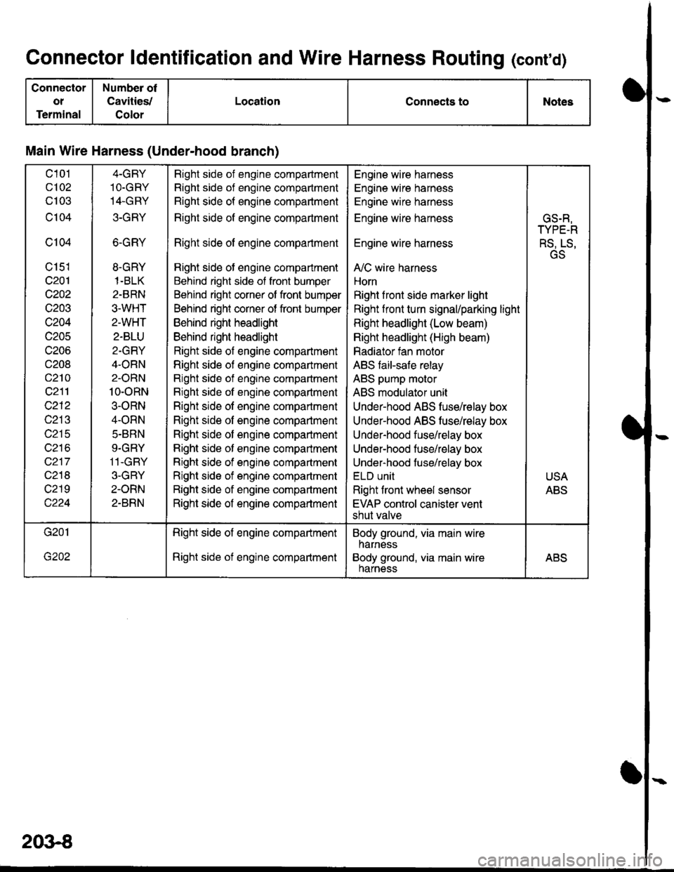
Connector ldentification and Wire Harness Routing (conrd)
Connector
ot
Terminal
Number of
Cavities,/
Color
LocationConnects toNotes
Main Wire Harness (Under-hood branch)
c101
c102
cl03
c104
c104
c151
c201
c202
c203
c204
c205
c206
c208
c210
c211
c212
c213
c215
wz to
c217
c218
c219
4-GBY
1O.GRY
14.GRY
3-GRY
6-GRY
8.GRY
1-BLK
2-BRN
3.WHT
2-WHT
2-BLU
2-GRY
4-ORN
2-ORN
10-oRN
3-ORN
4-ORN
5.BRN
9.GRY
11-GBY
3-GBY
2-ORN
2-BRN
Right side of engine compadment
Right side of engine compartment
Right side of engine compartment
Right side of engine compartment
Right side of engine compartment
Right side of engine compartment
Behind right side of front bumper
Behind right corner of front bumper
Behind right corner of front bumper
Behind right headlight
Behind right headlight
Right side of engine compartment
Righl side of engine compartment
Right side of engine compartment
Bight side of engine compartment
Right side of engine compartment
Right side of engine compartment
Right side of engine compartment
Right side of engine companment
Right side of engine compartment
Right side of engine compartment
Right side of engine compartment
Right side of engine compartment
Engine wire harness
Engine wire harness
Engine wire harness
Engine wire harness
Engine wire harness
A,/C wire harness
Horn
Right f ront side marker light
Right front turn signal/parking light
Right headlight (Low beam)
Right headlight (High beam)
Radiator fan motor
ABS faiFsafe relay
ABS pump molor
ABS modulator unit
Under-hood ABS fuse/relay box
Under-hood ABS tusehelay box
Under-hood fuse/relay box
Under-hood fuse/relay box
Under-hood fuse/relay box
ELU UNII
Right front wheel sensor
EVAP control canister vent
shut valve
GS.R,
TYPE-R
RS, LS,
GS
USA
ABS
Right side of engine compartment
Right side of engine compartment
Body ground, via main wire
harness
Body ground, via main wireharnessABS
2()3€
Page 1632 of 1681
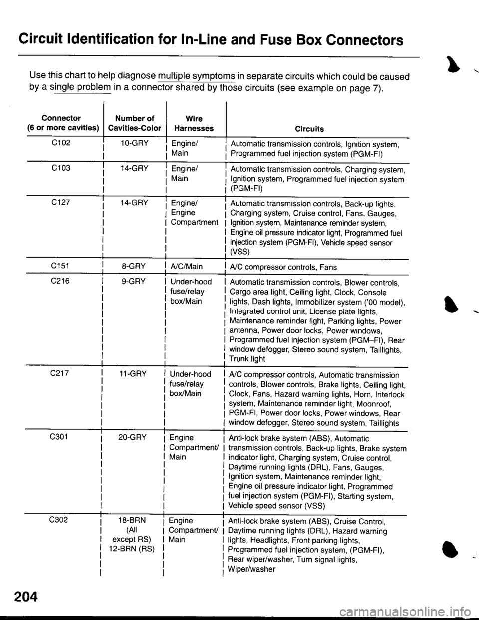
Circuit ldentification for In-Line and Fuse Box Connectors
Use this chart to help diagnose multiple symptoms in separate circuits which could be caused
by a single problem in a connector shared by those circuits (see example on page 7).
Connector
(6 or more cavities)
Number of
Cavities-Color
Wire
Harnesses
Engine/
Main
Engine/
Engine
Compartment
I Automatic transmission controls, lgnition system,
i Programmed fuel injection system (PGM-F|)
Automatic transmission controls, Charging system,
lgnition system, Programmed fuel injection system(PGM-FI)
Automatic transmission controls, Back-up lights,
Charging system, Cruise control, Fans, Gauges,
lgnition system, Maintenance reminder system,
Engine oil pressure indicator light, Programmed fuel
injection system (PGM-Fl), Vehicle speed sensor
ffss)
| {c/Main! A,/C compressor controls, Fans
Under-hood
fuse/relay
box/Main
Automatic transmission controls, Blower controls,
Cargo area light, Ceiling light, Clock, Console
lights, Dash lights, lmmobilizer system ('00 model),
Integrated control unit, License plate lights,
Maintenance reminder light, Parking lights, Power
antenna, Power door locks, Power windows,
Programmed fuel iniection system (PGM-Fl), Rear
window defogger, Stereo sound system, Taillights,
Trunk lioht
11-GRY
18-BBN
(4il
except BS)
12-BBN (RS)
Under-hood
fuse/relay
box/Main
Engine
CompartmenV
Main
Engine
CompartmenU
Main
lr,/C compressor controls, Automatic transmission
controls, Blower controls, Brake lights, Ceiling light,
Clock, Fans, Hazard warning lights, Horn, Interlock
system, Maintenance reminder light, Moonroof ,PGM-FI, Power door locks, Power windows, Rear
window defogger, Stereo sound system, Taillights
Anti-lock brake system (ABS), Automatic
transmission controls, Back-up lights, Brake system
indicator light, Charging system, Cruise control,
Daytime running lights (DRL), Fans, Gauges,
lgnition system, Maintenance reminder light,
Engine oil pressure indicator light, Programmed
tuel injection system (PGM-F|), Starting system,
Vehicle speed sensor (VSS)
Anti-lock brake system (ABS), Cruise Conkol,
Daytime running lights (DRL), Hazard warning
lights, Headlights, Front parking lights,
Programmed fuel injection system, (PGM-Fl),
Rear wiper/washer, Turn signal lights,
Wiper/washer
204
Page 1633 of 1681
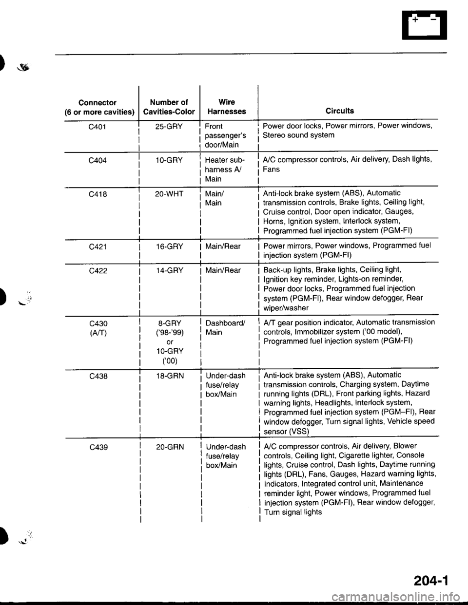
)ot
Connector
(6 or more cavities)
Number of
Cavities-Color
25-GRY
1O-GRY
Wire
Harnesses
Front
passenger's
door/Main
Heater sub-
harness A,/
Main
Circuits
Power door locks, Power mirrors, Power windows,
Stereo sound svstem
fuC compressor controls, Air delivery, Dash lights,
Fans
transmission controls, Brake lights, Ceiling light,
Cruise control, Door open indicator, Gauges,
Horns, lgnition system, Interlock system,
Programmed fuel injection system (PGM-Fl)
Main/
Main
Anti-lock brake system (ABS), Automatic
16.GRYMain/RearPower mirrors, Power windows, Programmed tuel
injection system (PGM-Fl)
14-GRYMain/RearBack-up lights, Brake lights, Ceiling light,
lgnition key reminder, Lights-on reminder,
Power door locks, Programmed fuel iniection
system (PGM-Fl), Rear window defogger, Rear
wiDer/washer) -io
tl
c430
(An)
8-GRY
(e8-'ee)
or
1O-GRY
(00)
18-GRN
Dashboard/
Main
Under-dash
fuse/relay
box/Main
A/T gear position indicator, Automatic transmission
controls, lmmobilizer system ('00 model),
Programmed fuel injection system (PGM-Fl)
Anti-lock brake system (ABS), Automatic
transmission controls, Charging system, Daytime
running lights (DBL), Front parking lights, Hazard
warning lights, Headlights, lnterlock system,
Programmed fuel injection system (PGM-Fl), Rear
window defogger, Turn signal lights, Vehicle speed
c43920-GRNUnder-dash
fuse/relay
box/Main
sensor (VSS
L/C compressor controls, Air delivery, Blower
controls, Ceiling light, Cigarette lighter, Console
lights, Cruise control, Dash lights, Daytime running
lights (DRL), Fans, Gauges, Hazard warning lights,
Indicators, lntegrated control unit, Maintenance
reminder light, Power windows, Programmed fuel
injection system (PGM-Fl), Rear window defogger,
Turn signal lights
)
204-1