1998 HONDA INTEGRA Starter
[x] Cancel search: StarterPage 1408 of 1681
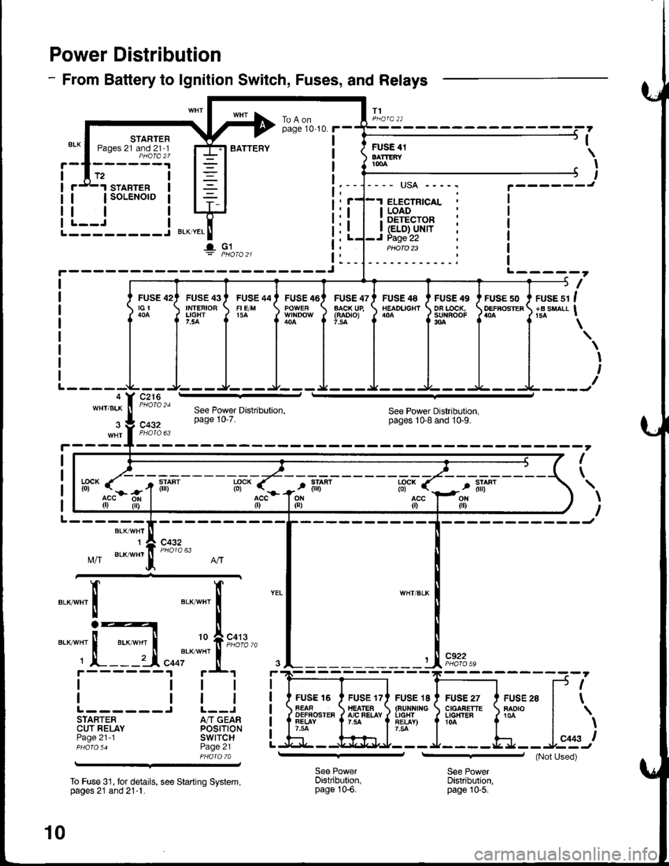
Power Distribution
- From Battery to lgnition Switch, Fuses, and Relays
T1
STARTERPages 21 and 21-1PHOfa 27
FUSE 42tGt
c216
STARTER
| | soLENorD
tlL--J I--------J BLKTYEL
I- G1
I
ILI (ELD} UNITI Page 22
I LOAD: DETECTOR
ELECTNICAL
PHOTO 23
BATTEFYFUSE 4tBATTEAYtmA
,
I
I
L-----?
I
FUSE 43IMTEFIOBLIGHT7.5A
FUSE 44FI E/M15A
FUSE 46FUSE 47AACK UE(RAOTO)7.la
FUSE 48NEADLIGHTFUSE 49DA LOCK,su{BooF304
FUSE 50OEFFOSTERruse sr I+B suaLl I
\
I
I
WH'/BLKSee Power Distribution,pages 1Gg and 10-9.c432
I
\
BLK/WHT'I
Mff BLK/wHr
c432
".__",x'
c922
FUSE I8(aurxf{GIIGHTRE!AY)7.54
FUSE 27C|GAAETTELG}T'ER104
FUSE 28RADIO
f.--
r(
l*,)
See PowerDistribution,page 10-6.
See PowerDistribution,page |0-5.
--':'[E
I
IL------STARTERCUT RELAYPage 21 -1
To Fuse 31, tor details, see Starting System,pages 21 and 21-1.
See Power Distribution,page 10'7.
lff- (".-
r-r
tili*lff* r
acc{r)
FUSE 16AEAAOEFFOSTEAFELAY7.54
If"a*t "t I
i
'o f,""f#
"ooi'*
*"'
i.t r+t
ttl
trlJ L--JA/T GEARPOStTtONswtTcHPage 21PHA|A 7A
10
(Not Used)
Page 1431 of 1681
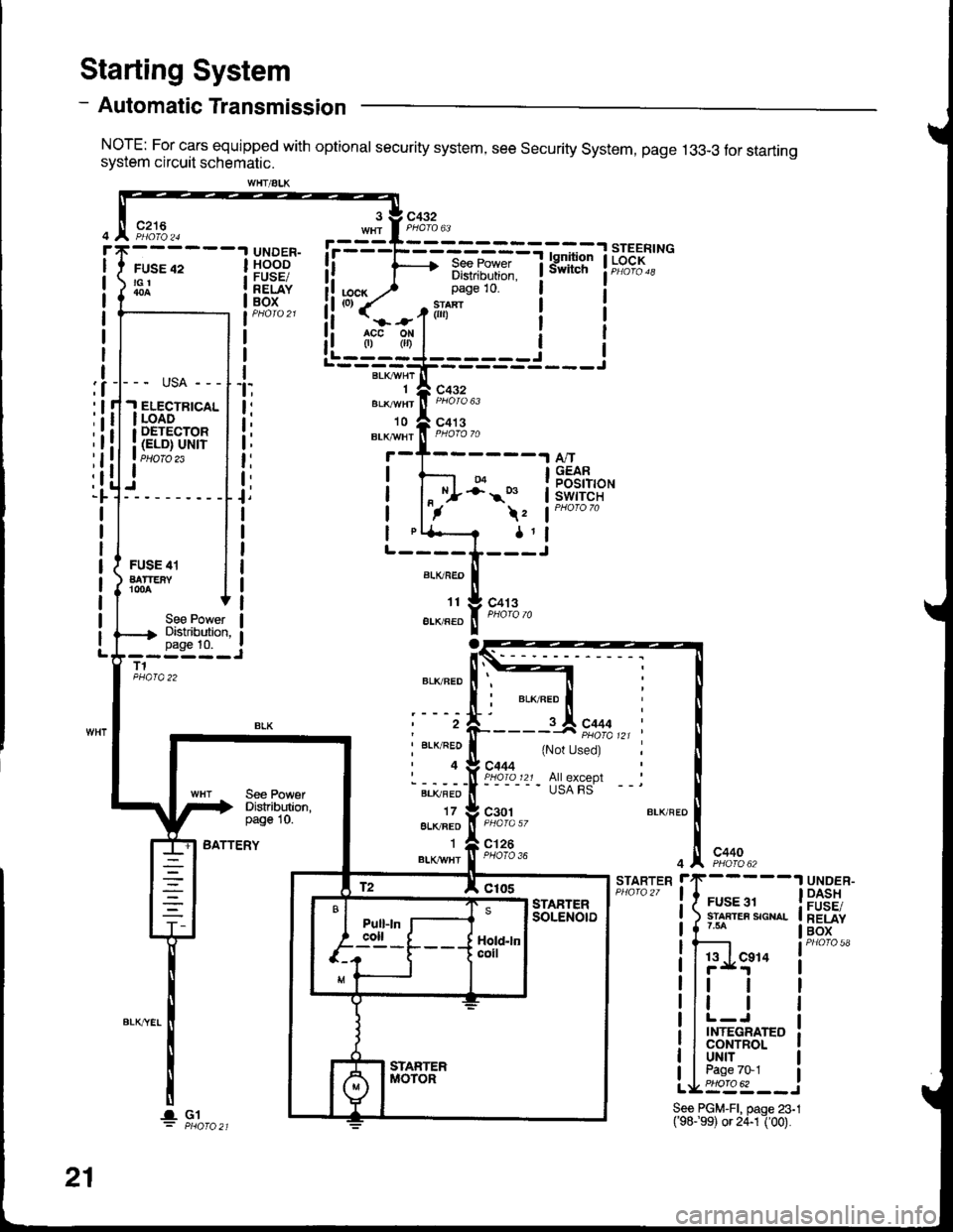
- Automatic Transmission
NorE: For cars equipped with optional security system, see security system, page 13g-3 tor startrngsystem circuit schematic.
Starting System
c216
FUSE 42tGt
UNDER-HOODFUSE/RELAYBOX
See PowerDistributian,page 10.
liu.) 3:i:it1-i*!
i!'''{=o1ili"' i i!i (=r.f(',ii i I
!i rfi,l.l i I
!L----J------j Ir'---BLK;HrT---------=---r
".o"rnrfi F,i% u.,
'to A co' s
3 V C432
BLr!,Y/Ht ll PHoro 70
04-;' s
\z
1l
t:
t,
t;
t:
t:
t,N^/.
A,/TGEARPOSITIONswtTcH
ALKFEO
't1
EIIVRED
BLKFED
t2
I BLK/RED
'4
BLI(FED
178LK/BEO'I
BLKII/HT
FUSE 41BATTEiYr00A
To
c413
See PowetDistribution,page 10.--i--;-JT1
BATTERY
c444
{Not Used)
All exceplUSA FS
c301
c126PHOTO 36c4404 ^, PHO|O 62
STARTERrrF-----1
! i rur..r !| snnrea sour- || 1 '* |
! Ir-'Lg"' i
llttl
llr | |
llL-J Ir I INTEGRATEo I! I CONTROL I
I luNrr I
tIbEt:_J
UNDER-DASHFUSE/RELAYBOX
WHT/ALK
--- usA ---
.I ELECTBTCALI LOADI DETECTOR
i (ELD) uNrr. PHOIO 23I
21
lGlSee PGM-FI, paqe 23.1('98.'99) or 24-1I OO).
Page 1432 of 1681
![HONDA INTEGRA 1998 4.G Workshop Manual - Manual Transmission
NOTE: For cars equipped with optional security system, see security system, page 133-3 for starting
system circuit schematic.
c432
FUSE 42tGl
c216
r
I
I
I
I
I
I
I
I
I
]
UNDER.HOO HONDA INTEGRA 1998 4.G Workshop Manual - Manual Transmission
NOTE: For cars equipped with optional security system, see security system, page 133-3 for starting
system circuit schematic.
c432
FUSE 42tGl
c216
r
I
I
I
I
I
I
I
I
I
]
UNDER.HOO](/manual-img/13/6069/w960_6069-1431.png)
- Manual Transmission
NOTE: For cars equipped with optional security system, see security system, page 133-3 for starting
system circuit schematic.
c432
FUSE 42tGl
c216
r
I
I
I
I
I
I
I
I
I
]
UNDER.HOODFUSE/RELAYBOX
ELECTRICALloAoDETECTOR(ELD) UN|T
START(10
c432
.Joil0t)
BLKWHT
1
BLK/IVHT
(o) ,t-,>
0)
,i
I
l
Ia
I
I
I
I
BLKA''HT II--2 A cqqz
"4
".u,".0^ tr-
- -----
t I coee
Hifr*',;*-"J
":-r
"*'
: See Ground
I Rl"i:b,*?"
""1;
' PHOIO 56
STARTERCUTRELAY
See PowerDistribution,page 10.
T1PHO|Q22
BLK/REO
BLK/BEO
a=z
lt
lta c444
Used)
c444All exceptUSA RS
See PolYerDistribution,page 10.
BLK/REO
1
ALK/WHI
c301
c126PHOTA 36c440
BATTERYSTARTERrrF-----1
! { H:.i,r'",""^. I
li ?.ea I
!l';Lg" i
|r | |
ill l lllL-J I! I INTEGRATED ]| | coNrRoL I
Ll'l,l't--i
UNDER.DASHFUSE/RELAYBOX
See PGM'Fl, page 23-l('98-99) or 24-1 ('00).
t2 A Clos
-a- G1
21-1
Page 1436 of 1681
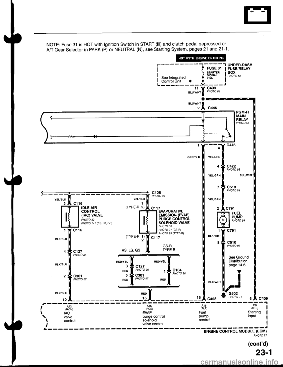
NOTE: Fuse 31 is HOT with lgnition Switch in START (lll) and clutch pedal depressed or
A/T Gear Selector in PARK (P) or NEUTRAL (N), see Starting System, pages 21 and 21-1.
r---------1----''l
i I FusE31 I; STARTER
I see Intesrared i ;LSir' !
L9"1"''�"'L_:-____..i11 Y C439*",l'"'tr F'*13*
UNDER-DASHFUSE/RELAYBOX
PGM-FIMAINRELAY
oBLU wHr i2 A' C446
"",."-F"'q--
I "..,""'"T
t*'
PORATIVE I"-fi::
ilf
l$tT*"", t-il1-ll$,":,:{}fltrt I Hlui#,'1 l( cl 16 l-iL-l :::l: i: :i'": " ll 1 Y c7s1
,:: ,{;,
-i::'ff"H:'
1"".*t*;-
,F
w,,l.L5j*
124------ -r:A'-----------:-A L4u! o.Av'ur-----=-r
i ,|o3". rAJBr ,|1f;, ,"$"r I
rAc EVAP Fuel start'ng I vatue Purgs conttol PumP - InPu Ivatue Putgs conttol PumP - rrrpur I control solenoid control
I valve control I
.l-------ENGINE CONTROL MODULE (ECM}
(cont'd)
23-1
Page 1554 of 1681
- How the Circuit Works
The security system control unit has a 3 position
switch: Manual. Auto. and Auto Lock. Here's what
happens when you arm the system, regardless ol
the switch position:
o The parking lights will flash once.
. The security indicator will flash once per second
after the system is armed.
With the switch in the Manual position, the security
system can only be armed by using the remote
control transmitter, After you remove the key from
the ignition and close all doors, the hood (if
equipped with the optional hood switch), the hatch
or trunk. Dress the lock button on the transmitter
and the system will arm (if the system is in the beep
sound mode, the horn will sound once). The doors
will automatically lock when the system is armed.
With the switch in the Auto position, the security
system will arm itself within about 20 seconds after
you turn the engine off, remove the key from the
ignition, and close the halch or trunk, the hood (if
equipped with the optional hood switch), or last
door. lf a door is opened during the 2o-second exit
delay time, the timer will reset itself . The remote
control transmitler can still be used to arm the
system with the switch in Auto position (see manual
for details).
With the switch in Auto Lock position, the security
system will arm itself and lock the doors about 20
seconds after you turn the engine of{, remove the
key from the ignition, and close the hatch or trunk,
the hood (if equipped with the optional hood
switch), or last door. lf a door is opened during the
2o-second exit delay time, the timer will reset. The
remote control transmitter can still be used to arm
the system in the Auto Lock position.
Triggering the Alarm
After the security system is armed, the sound ot
breaking glass or the opening of a door, hood,
hatch or trunk will trigger the alarm, and cause
the following:
r The horn will sound for30 seconds.
The optional siren will sound lor 60 seconds.
. The parking lights will flash.
. The security indicator LED will flash twice per
second.
. The starter will be disabled.
At the end of the alarm cycle, the system will
automatically rearm.
Disarming the Security System
There are two ways to disarm the security system:
. With the transmitter
o With the disarm/valet switch
When the system is disarmed, regardless of the
method used, the parking lights will flash two times if
the alarm has not been triggered and three times if
the alarm has been triggered. To disarm the system
with the transmitter, press the unlock button (if the
system is in the beep sound mode, the horn will
sound two times if the alarm has not been triggered,
however, will sound three times if the alarm has
been triggered). The driver's door will unlock
(pressing the unlock button twice will unlock all
doors).
To disarm the security system using the
disarm/valet switch, enter the car and turn the
ignition switch to ON (ll) then press the disarm/valet
switch button. lf you open the door when the control
unit switch is in Auto or Auto Lock, a 2o-second
entry delay will give you time to disarm the system.
However, when the system is armed by the
transmitter, the entry delay time is changed to zero
seconds, and the alarm is triggered as soon as you
oDen the door.
ldentifying Tripped Sensors
The system will indicate the sensor which triggered
the alarm through the security indicator LED. While
sitting inside the vehicle wlth the key out of the
ignition switch, all doors, the hood (if equipped with
the optional hood swilch), the hatch or trunk must be
closed. Press and hold the disarm/valet switch.
Press the lock button and then the unlock button of
the transmitter. Belease the disarm/valet switch. The
status LED will blink according to the following code:
Sensors
Door
Trunk/Hatch
System Switches
Glass Breakage
Hood (Optional)
Number ol Flashes
1 blink, pause, repeat
2 blinks, pause, repeat
3 blinks, pause, repeat
4 blinks, pause, repeat
5 blinks, pause, repeat
For further operating instructions and troubleshooting,
see the security system owner's manual.
133-5
Page 1596 of 1681
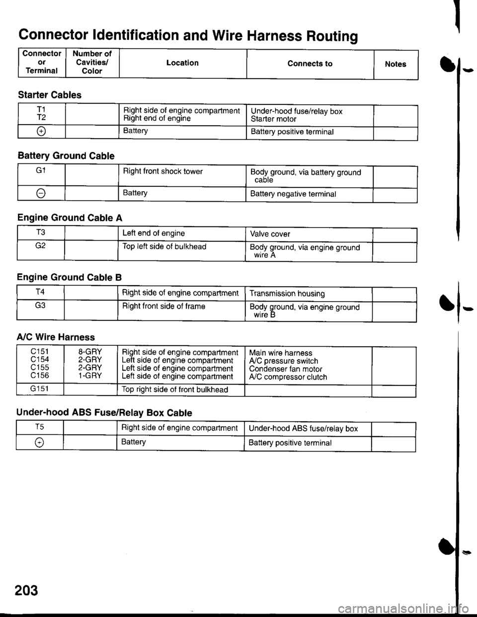
Connector ldentification and Wire Harness Routing
Connector
OT
Terminal
Number of
Cavities/
Color
LocationConnecls toNotesI
fl-
Starter Cables
T1
T2Right side of engine compartmentRight end of engineUnder-hood fuse/relav boxStarter motor
oBatteryBattery positive terminal
Battery Ground Cable
lRight front shock towerBodyground, via battery ground
ABatteryBattery negative terminal
Engine Ground Cable A
T3Left end of engineValve cover
Top left side ol bulkheadBody ground, via engine ground
Engine Ground Cable B
T4Right side of engine compartmentTransmission housing
Right front side of trameBody ground, via engine ground
wrre b
A,/C Wire Harness
Under-hood ABS Fuse/Relay Box Cable
203
c151
c'154utSc
u tco
8-GRY
2-GRY
2-GRY
1-GRY
Right side ol engine compartmentLeft side of engine compartmentLeft srde of engine compartmentLeft side of engine compartment
Main wire harness
A'lC pressure switch
Condenser tan motorA,/C compressor clutch
lrlclTop right side ot front bulkhead
T5Right side of engine compartmentUnderhood ABS fuse/relav box
\,BatteryBattery positive terminal
Page 1598 of 1681
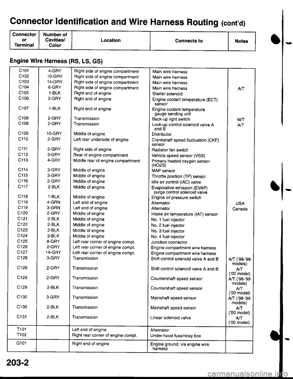
Connector ldentification and Wire Harness Routing (cont,d)
Connector
or
Terminal
Number ot
Cavities/
Color
LocationConnects toNotes
Engine Wire Harness (RS, LS, GS)
c101
c102
c103
c104
c105
c106
c 107
c108
c108
c'1 09
c110
c111
cl12
c113
c'114
c115
c116
c117
c118
c119
c1 19
c120
c121
c122
c123
c124
cl25
cl26
c127
Ql28
c128
c129
c 129
c130
c'l30
c131
4.GRY
1O.GRY
14-GRY
6-GRY
1.BLK
2-GRY
,1-BLK
2-GRY
2.GRY
1O-GRY
2-GRY
2-GRY
3-GRY
4-GRY
3-GRY
3-GRY
2-GRY
2.BLK
.1-BLK
4-GRN
3-GRN
2-GRY
2.BLK
2-BLK
2-BLK
2.BLK
8-GRY
2-GRY
14-GRY
3-GRY
2.GRY
2.GRY
2-BLK
3-GRY
2-BLK
2-BLK
Right side of engine compartment
Right side of engine compartment
Right side ot engine compartment
Right side of engine compartment
Right end of engine
Right end of engine
Right end of engine
Transmission
Transmission
lvliddle ol engine
Lett rear underside of engine
Right side ol engine
Rear of engine compartment
Middle rear ol engine compartment
Middle ol engine
Middle of engine
Middle ol engine
l\4iddle of engine
Middle of engine
Left end ot engine
Lett end of engine
Middle of engine
N,liddle ol engine
Middle of engine
Middle of engine
Middle of engine
Left rear corner of engine compt.
Lelt rear corner of engine compt.
Left rear corner of engine compt.
Transmission
Transmission
Transmission
Transmission
Transmission
Transmission
Transmission
Main wire harness
Main wire harness
Main wire harness
Main wire harness
Starter solenoid
Engine coolant temperature (ECT)sensor
Engine coolant temperaturegauge sending unit
Back-up light switch
Lock-up control solenoid valve Aand B
Distributor
Crankshaft speed fluctuation (CKF)sensor
Radiator fan switch
Vehicle speed sensor (VSS)
Primary heated oxvoen sensor(H02s)
MAP sensor
Throttle position (TP) sensor
ldle air control (lAC) valve
Evaporative emission (EVAP)purge control solenoid valve
Engine oil pressure switch
Alternator
Alternator
Intake air temperature (lAT) sensor
No. I fuel injector
No. 2 fuel injector
No. 3 tuel injector
No. 4 fuel injector
Junction connector
Engine compartment wire harness
Engine compartment wire harness
Shitt control solenoid valve A and B
Shift control solenoid valve A and B
Countershaft speed sensor
Countershatt speed sensor
lvtainshatt speed sensor
Mainshaft speed sensor
Linear solenoid valve
NT
[/VT
A"/T
USA
Canada
A/T (98199models)
AIT('00 model)
A,/T ('98-'�99models)
('00 model)
A,/T f98-'99models)
Atf('00 model)
AN('00 model)
T101
T102
Left end of engine
Right rear corner of engine compt.
Alternator
Under-hood fuse/relay box
G'101Right end ot engineEngine ground, via engine wirenarness
o
I
203-2
Page 1600 of 1681
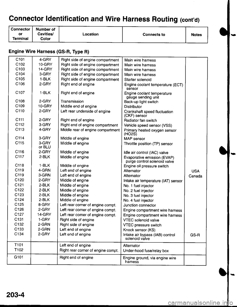
Connector ldentification and Wire Harness Routing (conrd)
Connector
ol
Terminal
Number of
Cavities/
Golor
LocationConnects toNotes
Engine Wire Harness (GS-R, Type R)
c101
c102
c103
c104
U IUC
c106
c107
c108
c109
c110
c111
c112
c113
c114
c115
c116
c117
c118
c11 9
c119
c120
c121
cl22
c123
vtzl
wt10
c127
c131
c132
c133
c134
4-GRY
1O-GRY'I4-GRY
3-GRY
1 -BLK
2-GRY
1.BLK
2-GRY
1O-GRY
2-GRY
2-GRY
3-GRY
4-GRY
3-GRY
3.GRY
or BLU
2-GRY
2-BLK
1 -BLK
4-GRN
3-GRN
2.GRY
2-BLK
2-BLK
2-BLK
2-BLK
8-GRY
2.GRY
14-GRY
1-GRY
2-GRN
2-GRN
2-GRY
Right side of engine compartment
Right side of engine compartment
Bight side of engine compartment
Right side of engine compartment
Right side of engine compartment
Right end of engine
Right end of engine
Transmission
Middle end of engine
Left rear underside of engine
Right end of engine
Right end of engine compartment
Middle rear of engine compartment
Middle of engine
Middle of engine
Middle of engine
Middle of engine
Middle of engine
Left end of engine
Left end of engine
Middle of engine
Middle of engine
Middle of engine
Middle of engine
Middle of engine
Left rear corner of engine compt.
Left rear corner of engine compt.
Left rear corner of engine compt.
Right side of engine
Right side of engine
Left end of engine
Left end of engine
Main wire harness
Main wire harness
Main wire harness
Main wire harness
Starter solenoid
Engine coolant temperature (ECT)
sensor
Engine coolant temperaturegauge sending unit
Back-up light switch
Distributor
Crankshaft speed f luctuation(CKF) sensor
Radiator fan switch
Vehicle speed sensor (VSS)
Primarv heated oxvoen sensor(Hozs)
MAP sensor
Throttle position (TP) sensor
ldle air control (lAC) valve
Evaporative emission (EVAP)purge control solenoid valve
Engine oil pressure switch
Alternator
Alternator
Intake air temperature (lAT) sensor
No. 1 fuel injector
No. 2 fuel injector
No. 3 fuel injector
No. 4 fuel injector
Junction connector
Engine compartment wire harness
Engine compartment wire harness
VTEC solenoid valve
VTEC pressure switch
Knock sensor (KS)
Intake air bypass (lAB) controlsolenoid valve
USA
Canada
GS.R
T101
r102
Left end of engine
Right rear corner of engine compt.
Alternator
Under-hood fuse/relay box
G101Right end of engineEngine ground, via engine wirenarness
203-4