Page 673 of 1681

Steering Wheel
Removal
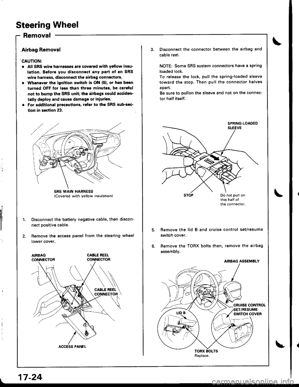
Airbag Removal
'CAUTION:
. All SRS wiro harne33e3 ar€ coverad with yellow insu.
lation. Beforo you di3connect Eny part of En SRS
wiro harn6ss, disconnsct the airbag conncctors.
. Whenaver ths ignition switch is ON {ll}, or ha3 b.cn
turned OFF lor l.3s than thrcc minuto3, be cErs{ul
not to bump th6 SRS unh; the airbags could rcciden-
tally deploy and cause damsgo or iniurias'
. Fo. additional preclution3, rofer to tho SRS sub-soc'
tion in 36ction 23,
Disconnect the battery negative cable, then discon-
nect Dositive cable.
Remove the access panel from the steering wheel
lower cover.
CABLE REEL
L
SRS MAIN HARNESS
17-24
Disconnect the connector between the airbag and
cable reel.
NOTE: Some SRS system connectors have a spring
loaded lock.
To release the lock, pull the spring-loaded sleeve
toward the stop. Then pull the connector halves
apart.
Be sure to pullon the sleeve and not on the connec-
tor half itself.
Remove the lid B and cruise control set/resume
switch cover.
Bemove the TORX bolts then, remove the airbag
assembly.
SPRING.LOADED
AIRBAG ASSEMBLY
Page 678 of 1681
10. Remove the steering joint cover.
Remove the steering joint bolts, and move the iointtoward the column.
11.
JOINT COVER
12.
'13.
Disconnect the ignition switch connectors from the
under-dash fuse/relay box.
Remove the steering column by removing the
aftaching nuts and bolts.
17-29
Page 684 of 1681

Power Steering Pump
Replacement
NOTE: Before disconnecting the hoses from the pump,
place a suitable container under the vehicle.
1. Remove the belt by loosening the pump adjusting
bolt, mounting bolts and nuts.
2. Cover the Ay'C compressor with several shop towels
to protect it from spilled power steering fluid,
11 N.m11.1 kgf.m, 8 lbl ft)
PUMPINLET HOSE(Low-pressure)
O.RINGReplace.
ADJUSTTNGBOLT
?UMP MOUt'lTlNG BOLTS2a N.m (2.a kgf.m, 17 lbf.ftl
t
7.
Disconnect the pump inlet hose and the pump out-
let hose (High-pressure) trom the pump, and plug
them.
NOTE: Take care not to spill the fluid on the body
or parts. Wipe off any spilled fluid at once.
Remove the pump mounting bolts, then remove thepump.
NOTE:
. Do not turn the steering wheel with the pump
removed,
. Cover the opening of the pump with a piece oftape to prevent foreign materiai from entering
the oumo.
Connect the pump inlet hose and the pump outlet
hose (High-pressure). Tighten the pump fittings
securelv,
Loosely install the pump in the pump bracket with
the mounting bolts, nuts and adjusting bolt.
Installthe DumD belt.
CAUTION:
. Mako suro that the power staering belt is prop-
erly positioned on the pulleys.
a Do not gst powor 9t99ring fluid or greas€ on thepower steering bclt or pulley facos. Clesn off any
tluid or grea3a botoro installation
POWER STEERING BEI-T
Adjust the pump belt (see page 17-20).
Fill the reservoir to the upper level line (see page'11.211.
8.
a
17-35
Page 690 of 1681

Power Steering
Gearbox
Removal
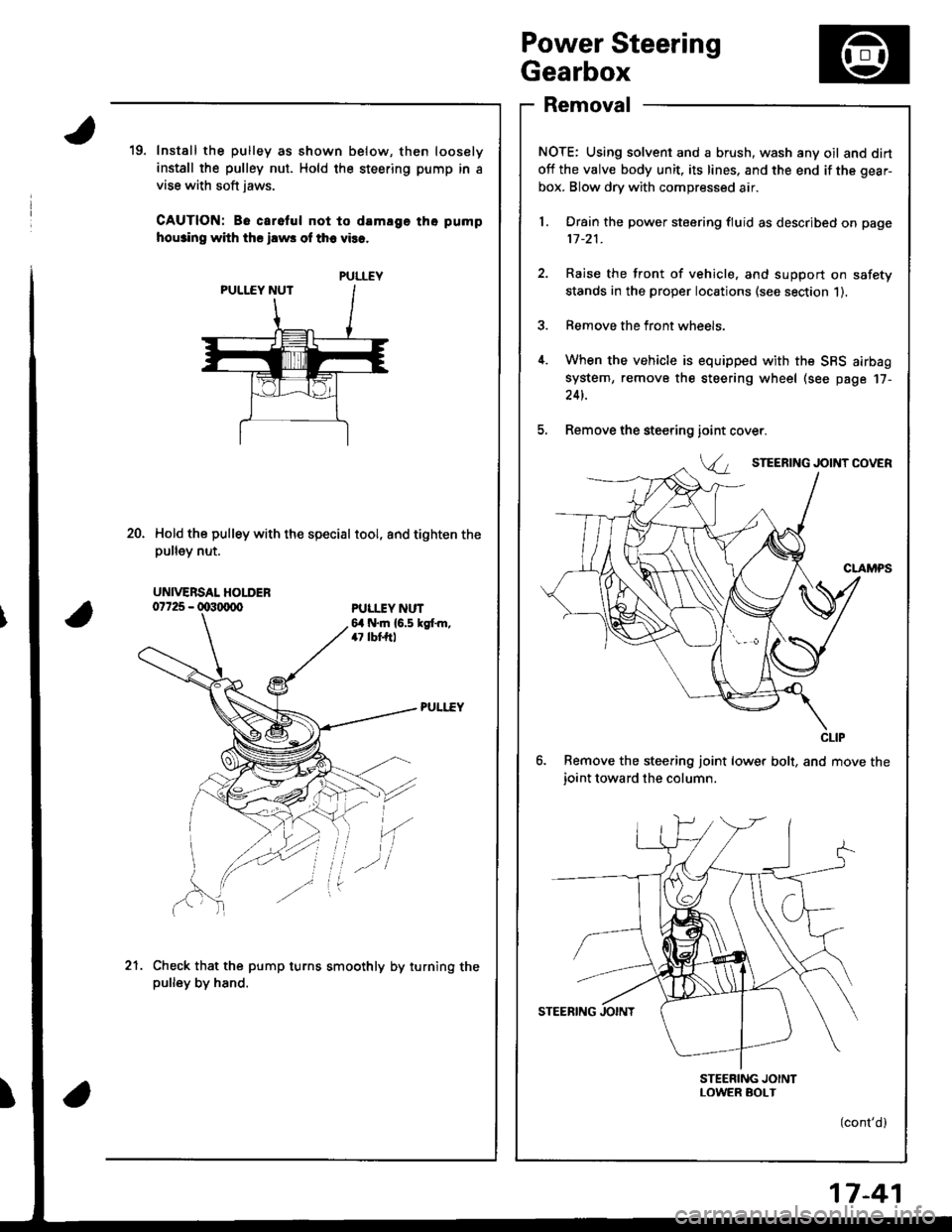
NOTE: Using solvent and a brush, wash any oil and dirt
off the valve body unit, its lines, and the end if the gear-
box. Blow dry with compressed air.
l. Drain the power steering fluid as described on page
11-21.
2. Raise the front of vehicle, and support on safety
stands in the proper locations (see section 1).
3. Remove the front wheels.
4. When the vehicle is equipped with the SBS airbag
system, remove the steering wheel (see page 17-
24t.
5. Remove the steering
6. Remove the steering joint lower bolt, and move the
ioint toward the column.
STEERING JOINTLOWER SOI-T
(cont'd)
19. Install the pulley as shown below, then loosely
install the pulley nut. Hold the steering pump in a
vise with soft jaws.
CAUTION: Be carelul not to damlge tho pump
hou3ino with ths ilws of th6 vies.
Hold the pulley with the special tool, and tighten thepu ey nut.
ioint
Va
20.
PULI.IY NUT6,1 N.m {6.5 kgt m,47 lbf,ftl
'(
Check that the pump turns smoothly by turning thepulley by hand.
.-l
21.
PULLEY
UNIVERSAL HOLDER
CLIP
17-41
Page 702 of 1681

Strsring Rack Roarssmbly
25. Coat the special tool with power steering fluid, and
slide it onto the rack, big end first.
26. Position the new O-ring and new piston seal ring on
the special tool, then slide them down towards big
end of the tool.
NOTE:
. Do not over expand resin seal rings. Install the
resin seal ring with care so as not to damage
them. After installation. be sure to contract the
seal ring using the specialtool (sizing tool).
. Replace piston's O-ring and sesl ring as a set.
27. Pull the O-ring off into the piston groove, then pull
the piston seal ring off into the piston groove on top
of the O-ring as shown.
Coat the piston seal ring and inside of the special
tool with power steering fluid.
Carefullv slide the tool onto the rack and over the
piston seal ring.
30. Move the special tool back and forth several times
to make the piston seal ring fit snugly in the piston.
28.
29.
PISTON
Replace.
31.Coat the sliding surface of the special tool and new
cylinder end seal with power steering fluid,
Place the seal on the special tool with its grooved
side facing opposite the special tool.
Grooved side.
CYLINOER END SEALReplace. 0797,t - 68D8OA
Apply a thin coat of grease to the inside of the spe-
cial tool, and install it on the steering rack.
CAUTION: Make sure the rack tecth do not lace
the 3lot in the special tool.
CYLINDER END SEALReplace.
CYLINDERSEAL SLIDER07974 - 6890800ot(cont'd)07974 - 6A1080A
17-5�3
Page 703 of 1681

Power Steering Gearbox
Reassembly {cont'd}
34. Separate the cylinder end seal from the special tool,
then remove the tool from the steerino rack.
CYLINDER END SEALReplace.
lnstall the backup ring on the steering rack. then
place the cylinder end seal to piston.
Grease the steering rack teeth, then insert the steer-
ing rack into the gearbox housing.
CAUTION: Be carelul not to damage to inner sur-
tace of the gearbox housing with the rack edges.
BACKUP BING
CYLINDER END SEAL
17-54
37.
38.
Set the gearbox in a press with the cylinder housing
facing upward.
Install the flange bolt into the end of the steering
rack until it bottoms in the hole. then back the
tlange bolt out 1/4 turn. Hold the flange bolt and
tighten the flange nut against the rack by hand.
Install the cylinder end seal into the bottom of the
cylinder by pressing on the bolt with a press as
shown.
CAUTION: Do not push on th€ boh with excossive
lorce; as it may damage thecylinder end seal.
Press
I
12 x 170 mm FLANGE BOLT
12 mm FLANGE NUT
Wrap vinyl tape around the rack end edges, and
coat the surface of the tape with the power steering
flu id.
NOTE: Make sure that the vinyl tape is wrapped care-
fully so that there is no stepped ponion.
Coat the inside surface of the new cvlinder end seal
with power steering fluid.
Install the cylinder end seal onto the steering rack
with its grooved side toward the piston.
CAUTION: When installing the cylinder end seal,
be careful not to damage the sealing lip face of the
seal with the edges of the steering rack,
Stak6d oosition.
39.
41.
Make sure the springis in the cylinder end
Page 709 of 1681
Power Steering Gearbox
Installation (cont'dl
11. Install the steering joint cover with the clamps and
clips.
lnstall the rear beam brace rod and return line
clamp on the rear beam.
NOTE: lnstall the rear beam brace toward the
return line clamp.
12.
CLIP
38 N.m 13.9 kgl'm,28 lbf tl)
17-60
13. Install the three way catalytic converter with the
new gaskets and new self-locking nuts, and connect
the secondary heated oxygen sensor (HO2S) con-
nector.
SECONOARYHEATED OXYGEN SENSOR CONNECTOR
22 N.m {2.2 kgf.m, 16lbIft)
Connect the shift linkage (M/T model: see section
13, A,,/T model; see section 14).
Thread the right and left tie-rod ends onto the rack
an equal number of turns.
14.
Page 725 of 1681
\
NOTE; Wash the knuckle and hub thoroughly in high
flash point solvent before reassembly.
5. Press a new wheel bearing into the knuckle using
the old bearing, a plate and a p.ess.
NOTE: Press the wheel bearing into the knuckle
with the pack seal (metal color) toward the inside. Be
careful not to damage the sleeve of the pack seal.
Installthe circlip securely in the knuckle groove.
SCREWS5x0.8mm4.9 N'm (0.5 kgf.m,3.5lbtftl
SPLASH GUARO
7. Install the splash guard and tighten the screws.
18-15
Installthe front hub on the knuckle using the special
tools and a press as shown,
CAUTION: Tako csro not to distort tho splash guard.
pre3s
DRIVER I0??a9 - 0010000 v
ATTACHMENT,62x68mm07746 - 00t0500
SPLASH GUARD
KNUCKLE
FRONT HUB
{cont'd)