Page 1071 of 1681
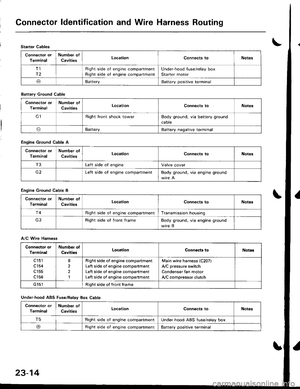
Connector ldentification and Wire Harness Routing
Starter Cables
Connectol ot
Terminal
Numbel of
CavitiesLocationConnects toNotes
Tl
r2
Right side of engine compartment
Right side oI engine compartment
Under-hood Iuse/relay box
Starter motor
oBatteryBattery positive terminal
Battely Ground Cable
Connector ol
Terminal
Numbel of
CavitiesLocationConnects toNotes
Right lront shock towerBody ground, via battery ground
caore
oBatteryBattery negative terminal
Engine Ground Cable A
Connector ol
Terminal
Number ol
CavitiesLocationConnects toNotes
T3Left side of engineValve cover
c2Left side oI engine compartmentBody ground. via engine ground
Engine Ground Cable B
Connector ol
Terminal
Numbel of
CavitiesLocationConnects toNot€s
r4Right side of engine compartmentTransmission housing
Right side of front frameBody ground, via engine ground
wire B
A/C Wire Harness
Connector or
Terminal
Number of
CavitiesLocationConnects toNotos
c 151
cl54
c156
8
2,l
Righr side of engine compartment
Left side of engine companment
Left side of engine compartment
Left side of engine compartment
Main wire harness (C207)
A,/C pressure switch
Condenser fan motor
ly'C compressor clutch
Right side of front frame
Under-hood ABS Fuse/Relav Box Cable
Connector or
Telminal
Number of
CavitiesLocationConnects toNotes
T5Right side o'f engine compartmentUnderhood ABS fuse/relay box
@Right side oI engine compaftmentBattery positive terminal
23-14
Page 1152 of 1681
'1.When reassembling the distributor, install the rotor
on the shatt so that it faces an the direction shown(toward the No. 1 cvlinder).
2.Align the index mark on rhe distributor ignition (Dl)
housing with the index mark on the end of the shaft.
INDEX MARKS
Distributor Reassemblylgnition Wire Inspection and Test
J
J)
23-95
,-
CAUTION: Carelully remove the ignition wires by pull-
ing on the rubber boots. Do not bend the wires; you might
break them inside.
'1 . Check the condition ot the wire terminals. lJ any ter-
minal is corroded, clean it, and if it is broken or dis-
torted. reolace the wire.
Check for broken,corroded, and bentterminals.
IGNITION WIRE
Connect ohmmeter probes and measure resistance.
lgnition Wire Resistance:
25 kO max. at 68oF {20oC}
IGNITION WIRE
3. It resistance exceeds 25 k0, replace the ignition wire.
)l-
Page 1162 of 1681
{
t
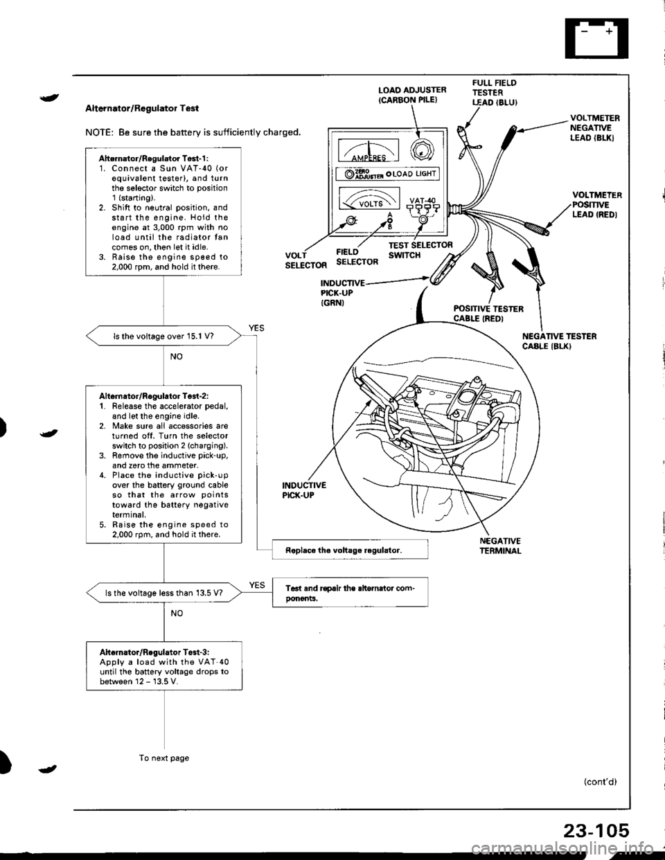
Alternator/Regulator Test
NOTE: 8e sure the battery is sufficiently charged.
LOAO ADJUSTER
ICARBON PILE)
FULL FIELDTESTERT.EAD (8LU)
POSITIVE TESTERCABLE IREDI
NEGATIVETERMINAL
VOLTMETERNEGATIVELEAO {BL|(}
VOLTMEIERPOSmVELEAD IREDI
FIELOSELECTOR
TEST SELECTORswtTcHVOLTSELECTOR
INDUCTIVEPICK.UP
INDUCTIVEPICK.UPIGRNI
NEGANVE TESTERCABLE IBLKI
)
)
{cont'd)
23-105
Ahernator/Regulator Tosl-1 :1. Connect a Sun VAT-40 (or
equivalent testerl, and turnthe selector switch to position'1 (starting).
2. Shift to neutral position, andstart the engine. Hold theengine at 3,000 rpm with noload until the radiator tancomes on, thon let it idle.3. Raise the engine sp€ed to2,000 rpm, and hold it there.
ls the voltage over 15.1 V?
Altsrnator/Rogulator Test-z:1. Release the accelerator pedal,
and let the engine idle.2, Make sure all accessories areturnod off. Turn the selectorswitch to position 2 (charging).
3. Remove the inductive pick-up,
and zero the ammeter.4. Place the inductive pick-up
over the battery ground cableso that the arrow points
toward the batterY negativeterminal,5. Raise the engine speed to2.000 rpm, and hold it there.
ls the voltage less than 13.5 V?
Ahelnstor/Regulator T$t-3iApply a load with the VAT-40until the battery voltage drops tobetween 12 - 13.5 V.
To next page
-
i-
Page 1188 of 1681
)
{
t.t
t.!
23-131
Fuel Gauge
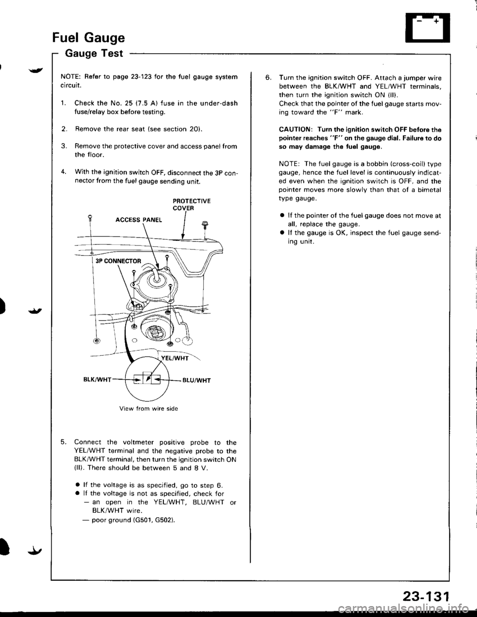
Gauge Test
NOTE: Refer to page 23-123 for the fuel gauge system
circuit.
1. Check the No. 25 (7.5 A) fuse in the under-dash
fuse/relay box before testing.
2. Remove the rear seat (see section 20).
Remove the protective cover and access panel from
the tloor.
With the ignition switch OFF, disconnect the 3p con-nector from the fuel gauge sending unit.
3.
4.
5.
PROTECTIVECOVER
Connect the voltmeter positive probe to the
YEL/WHT terminal and the negative probe to the
BLK/WHT terminal, then turn the ignition switch ON(ll). The.e should be between 5 and 8 V.
a lf the voltage is as specified, go to step 6.a lI the voltage is not as specified, check for- an open in the YEL/WHT, BLU/WHT or
BLK/WHT wire.- poor ground (G501, G502).
3P CONNECTOR
View from wire side
6.Turn the ignition switch OFF. Attach a jumper wire
between the BLKMHT and YEL/WHT terminals,
then turn the ignition switch ON {1.,.
Check that the pointer of the fuel gauge starls mov-
ing toward the "F" mark.
CAUTION: Turn the ignition switch OFF before the
pointer reaches "F" on the gauge dial, Failure to do
so may damage the tuel gauge.
NOTE: The fuel gauge is a bobbin (cross-coil) type
gauge, hence the fuel level is continuously indicat-
ed even when the ignition switch is OFF, and thepointer moves more slowlv than that ol a bimetal
rype gauge.
a lf the pointer ol the fuel gauge does not move at
all, replace the gauge.
a It the gauge is OK, inspect the fuel gauge send-
ing unit.
Page 1191 of 1681
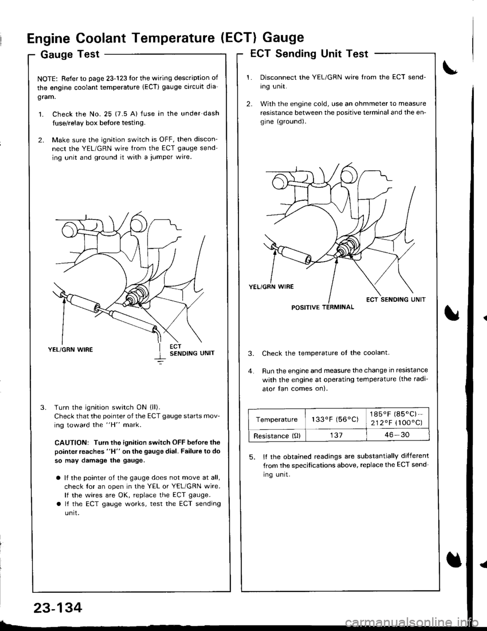
Engine Coolant Temperature (ECT) Gauge
Gauge Test
NOTE: Refer to page 23-123 for the wiring description of
the engine coolant temperature (ECT) gauge circuit dia-
gram.
1. Check the No. 25 (7.5 A) fuse in the under-dash
fuse/relay box before testing.
2. Make sure the ignition switch is OFF, then discon-
nect the YEL/GRN wire trom the ECT gauge send-
ing unit and ground it with a jumper wire.
YEL/GRN WIRESENDING UNIT
Turn the ignition switch ON (ll).
Check that the pointer of the ECT gauge starts mov-
ing toward the "H" mark.
CAUTION: Turn the ignition switch OFF before the
pointer reaches "H" on the gauge dial. Failure to do
so may damage the gauge.
a lf the pointer of the gauge does not move at all,
check lor an open in the YEL or YEL/GRN wire.
lf the wires are OK, replace the ECT gauge.
a lf the ECT gauge works, test the ECT sending
unrt.
ECT Sending Unit Test
Disconnect the YEL/GRN wire from the ECT send-
ing unit.
With the engine cold, use an ohmmeter to measure
resistance between the positive terminal and the en-
gine (ground).
Check the temperature ol the coolant.
Run the engine and measure the change in resistance
with the engine at operating temperature (the radi-
ator fan comes on).
5. It the obtained readings are substantially different
from the sDecifications above, replace the ECT send-
Ing unrt.
POSITIVE TERMINAL
Temperature133oF (56oC)1850F (85.C)-
212.F (100'C)
Resistance {O)13746-30
23-134
Page 1204 of 1681
)
t
t
Description
Ths cal is equipped with the tottowing devices to prevent inadvertenl shifting:
a Key cylinder with interlocked ignition key (Key Interlock System)
a shift lever with shift lock (shilt Lock system)
Key Interlock System:
When the shift lever is in any other position than @ or is not securely locked in @ (parking pin switch is ON), a solenoid
is activated, making it impossible to remove the ignition key from the ignition switch.
To be able to remove the key, the shift lever must be in E] and must be securely locked in this position {parking pin
switch must be turned oft by the lock pin)
The shift lever is in any othel position than El and the psrking pin switch is ON:
CYLINDER
The shitt lever is in l!] and the parking pin switch is OFF:
KEY CYLINOER
PARKING PIN
SHIFT LOCK LEVER
SHIFT LOCK LEVER
{t
23-147
Page 1338 of 1681
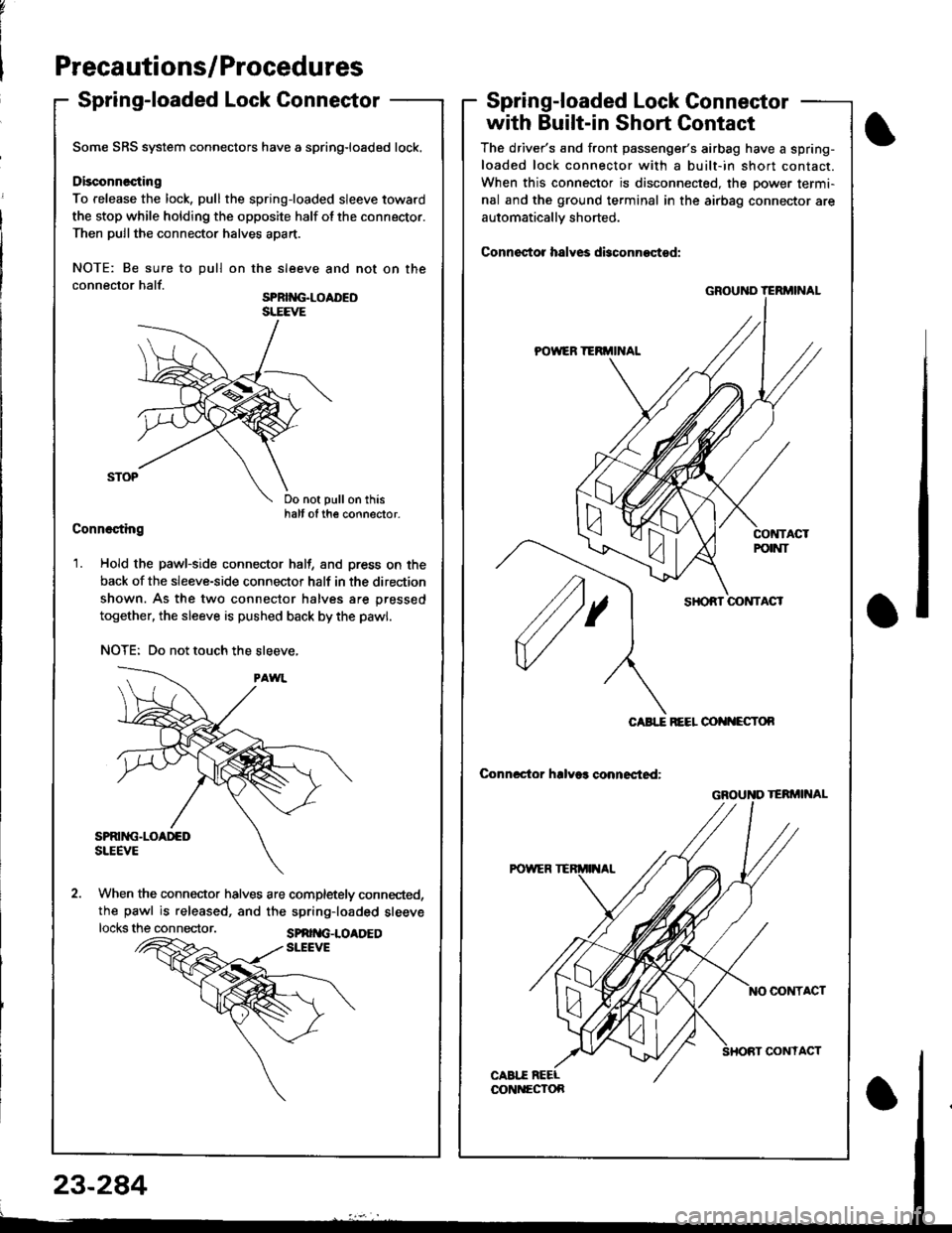
Precautions/Procedures
Spring-loaded Lock ConneetorSpring-loaded Lock Gonnector
with Built-in Short Contact
The driver's and front passenger's airbag have a spring-
loaded lock connector with a built-in short contact.
When this connector is disconnected, the power termi-
nal and the ground terminal in the airbag connector are
automatically shorted.
Connestor halves dbconnoctgd:
GROU D IERMINAL
SHONT OONTACI
CABTI REEL @I{I{ECTOF
Conncctor hrlvag connected:
Some SRS system connectors have a spring-loaded lock.
Disconn€cting
To release the lock, pull the spring-loaded sleeve toward
the stop while holding the opposite half ot the connector.
Then puilthe connector halves apart.
NOTE: Be sure to pull
connector half.
on the sleeve and not on the
SPRII{G.LOADEDsL"EEvE
Do not pullon thishalt of the connector-Conneqting
1. Hold the pawl-side connector half, and press on the
back of the sleeve-side connector half in the direction
shown. As the two connector halves are pressed
together, the sleeve is pushed back by the pawl.
NOTE: Do not touch the sleeve,
When the connector halves are completely connected,
the pawl is released, and the spring-loaded sleeve
locks the connector.SPRIM;-LOADEDSLECVE
acr
GAOUND TERi'INAL
@NTACT
CABII REELooNtrEcron
23-284
CONYACT
Page 1391 of 1681
How To Use This Manual
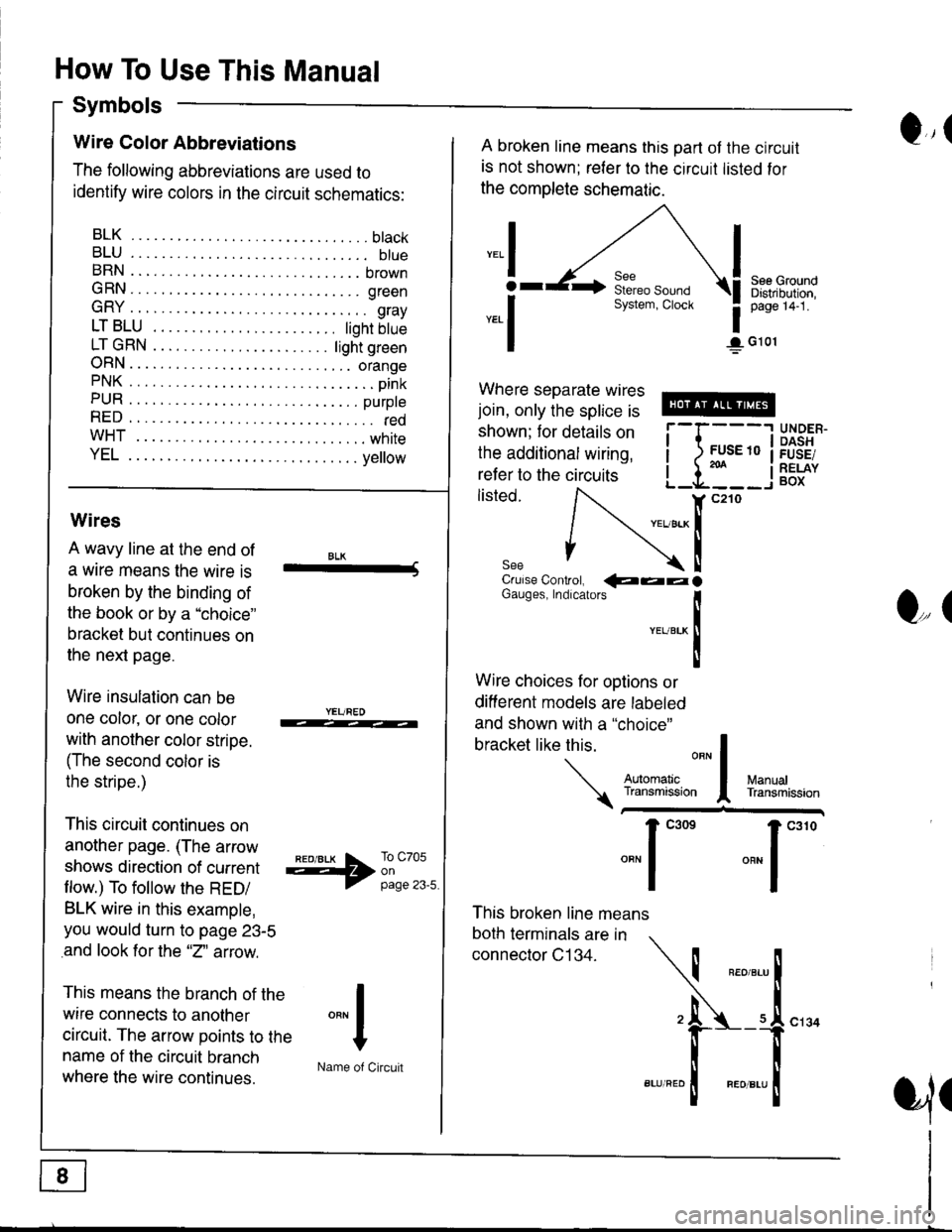
Symbols
Q,(Wire Color Abbreviations
The following abbreviations are used to
identify wire colors in the circuit schematics:
BLK.... .........btack
BLU.... ......... btueBRN .... ........ brown
GRN.... ........ green
GRY .... ......... gray
LTBLU . ..... tighrbtue
LTGRN. ....ljghtgreen
ORN.... ....... orangePNK.... ..........pink
PUR .... ........ purpte
RED .... .......... redwHT... .,.......white
YEL .... ........ ye ow
A broken line means this part ot the circuit
is not shown; reler to the circuit listed for
the complete schematic.
",.I
ar
*.1
See GroundDistribution,page 14-1.
1G101
Where separate wires
join, only the splice is
shown; for details on
the additional wiring,
refer to the circuits
listed.i-l{:i
;["
UNDER.DASHFUSE/RELAYBOX
Wires
A wavy line at the end of
a wrre means the wire is
broken by the binding of
the book or by a "choice"
bracket but continues on
the next page.
Wire insulation can be
one color, or one color
with another color stripe.
(The second color is
the stripe.)
This circuit continues on
another page. (The arrow
shows direction of current
flow.) To follow the RED/
BLK wire in this example,
you would turn to page 23-5
and look for the "2" aftow.
This means the branch of the
wire connects to another
circuit. The arrow points to the
name of the circuit branch
where the wire continues.
BLK-Crulse Controt, QaalGauges, Indrcarors
!YEUBTK
II
Wire choices for options or
different models are labeled
and shown with a "choice"
This broken line means
both terminals are in
connector C134.
bracketlikethis
*J
Q,(
ManualTransmission
*'ffil:,*"1"' *"1""0
I
"""1
H
Name of Circuit
cl34
a,ll